EP0709174A1 - Spritzgiessdüse - Google Patents
Spritzgiessdüse Download PDFInfo
- Publication number
- EP0709174A1 EP0709174A1 EP95116319A EP95116319A EP0709174A1 EP 0709174 A1 EP0709174 A1 EP 0709174A1 EP 95116319 A EP95116319 A EP 95116319A EP 95116319 A EP95116319 A EP 95116319A EP 0709174 A1 EP0709174 A1 EP 0709174A1
- Authority
- EP
- European Patent Office
- Prior art keywords
- nozzle
- sprue
- nozzle according
- adapter
- pivotally
- Prior art date
- Legal status (The legal status is an assumption and is not a legal conclusion. Google has not performed a legal analysis and makes no representation as to the accuracy of the status listed.)
- Granted
Links
Images


Classifications
-
- B—PERFORMING OPERATIONS; TRANSPORTING
- B29—WORKING OF PLASTICS; WORKING OF SUBSTANCES IN A PLASTIC STATE IN GENERAL
- B29C—SHAPING OR JOINING OF PLASTICS; SHAPING OF MATERIAL IN A PLASTIC STATE, NOT OTHERWISE PROVIDED FOR; AFTER-TREATMENT OF THE SHAPED PRODUCTS, e.g. REPAIRING
- B29C45/00—Injection moulding, i.e. forcing the required volume of moulding material through a nozzle into a closed mould; Apparatus therefor
- B29C45/17—Component parts, details or accessories; Auxiliary operations
- B29C45/26—Moulds
- B29C45/32—Moulds having several axially spaced mould cavities, i.e. for making several separated articles
- B29C45/322—Runner systems for distributing the moulding material to the stacked mould cavities
-
- B—PERFORMING OPERATIONS; TRANSPORTING
- B29—WORKING OF PLASTICS; WORKING OF SUBSTANCES IN A PLASTIC STATE IN GENERAL
- B29C—SHAPING OR JOINING OF PLASTICS; SHAPING OF MATERIAL IN A PLASTIC STATE, NOT OTHERWISE PROVIDED FOR; AFTER-TREATMENT OF THE SHAPED PRODUCTS, e.g. REPAIRING
- B29C45/00—Injection moulding, i.e. forcing the required volume of moulding material through a nozzle into a closed mould; Apparatus therefor
- B29C45/17—Component parts, details or accessories; Auxiliary operations
- B29C45/20—Injection nozzles
- B29C45/22—Multiple nozzle systems
Definitions
- This invention relates to injection molding machines using sprues, and more particularly, to a nozzle for use with a sprue which is capable of tolerating positioning error of the sprue while still forming a good seal therewith.
- multiple sprue bars can be used for delivering a split resin stream to the multi-level injection mold. That is, after the resin stream is split, the sprue bars carry the resin to the mold sections comprising the injection mold.
- the sprue bars typically a single source channel is used with a nozzle which breaks the single source channel into a plurality of channels aligned with the individual sprue bars.
- the sprue bars are attached with the mold section to which the molding resin is being delivered. Because injection molding devices generally move in the longitudinal or vertical direction, the sprue bars must be displaced with the platens.
- the sprue bars are not rigidly attached to the nozzle or in the channel from which the molding material is received and as such, the sprue bar arrangement must be designed so that the sprue bars will return to the channel splitting nozzle and reform a seal therewith.
- a sprue bar will feed the first and second level via channels in the mold plate between the two levels and another sprue bar will feed the third and fourth levels via channels in the mold plate between these two levels. Because of the progressive arrangement, these two sprue bars will necessarily be of different lengths. Additional variations in length occur due to each sprue bar being subject to thermal expansion effects.
- the prior art contains several devices directed toward injection units having single source and multiple channel supplies and corresponding attempts to solve the problems of creating reliable and repeatable seals between the multichannel nozzle and the sprue bars or similar channels.
- U.S. Patent No. 3,843,295 discloses an injection molding machine with adjustable nozzle length means.
- the machine comprises a plurality of split molds mounted upon a plurality of platens having parallel faces which reciprocate linearly for the opening and closing of the molds.
- Each mold cavity is filled through one or more nozzles extending from a fixed manifold portion of the machine.
- Each nozzle has a tip at least intermittently fitting against a nozzle seat.
- Length adjustment means are provided for each nozzle.
- the molding machine is operable at a plurality of temperatures, while still having a reciprocatingly retractable leakproof fit between certain nozzle tips and their nozzle seats.
- the spring based nozzle in FIG. 4 can accommodate a varying seating location wherein the resulting sealing force will vary according to the spring compression.
- FIG. 5 of the same patent shows a hydraulically actuated nozzle which also accommodates variation while maintaining a consistent sealing force.
- the use of hydraulic fluid in close proximity to hot resin is very dangerous since the fluid is flammable and the complexity of the fluid supply conduits increases costs and maintenance.
- U.S. Patent No. 3,915,610 discloses an alignment assembly for plastic injection molds.
- the alignment assembly includes a base communicating with a respective cavity and counterbore.
- a valve body is provided which has a stem portion slidably and sealingly disposed in the bore and a head portion disposed in the counterbore.
- the body has a through portion and the head portion is configured to mate with an ejection nozzle.
- the sealing fit of the stem allows axial movement of the body to react to the pressure generated in the cavity by the injected plastic and thereby be forced tightly against the nozzle to prevent flash.
- the apparatus disclosed relies upon the pressure of the plastic pushing the body 32 against the nozzle to maintain the seal between the nozzle and the body.
- the seal on the stem is created by a tangential contact between the stem and bore.
- the device requires that the stem pivot and slide in the bore to create and maintain alignment. This will result in wear on the spherical portion which will lead to clearance and eventually leakage. Also, since the contact area is
- U.S. Patent No. 4,299,791 discloses a method for preventing the drooling of a plastic injection molds and injection nozzles.
- the patent discloses a spring biased sprue member used to accommodate a change in resin volume following injection. The device deals with only one nozzle/sprue connection and the spring design does not serve to accommodate varying locations of nozzles through contact.
- U.S. Patent No. 4,917,595 discloses a nozzle touch sprue bushing device.
- the device is for use with a unit-type injection metal mold which includes a molding body having an inner mold element which is removably mounted on an outer frame of an injection molding machine.
- the sprue bush has a nozzle touch provided at a rear end thereof for fitting with an end of a nozzle of an injecting machine.
- the sprue bush also has a front end formed in such a fitting configuration so as to allow fitting engagement with a material admitting portion of the mold. All of the methods disclosed in this patent include spring means used to bias the intermediate conductor away from the inner mold inlet until the nozzle is engaged.
- the sprue bush is spring biased and substantially rigidly attached and does not allow for angular misalignments of the injection nozzle or the plate bush.
- the primary object of this invention is to provide an injector nozzle for use with a sprue or plurality of sprues which distributes a sealing force in a desired manner along the sprue or a plurality of sprues and is position error tolerant.
- Another object of this invention is to provide an injector nozzle for use with at least one sprue which does not require precision manufacturing yet still tolerates substantial misalignment.
- Still another object of this invention is to provide an injector nozzle for use with at least one sprue which requires no modifications to the existing injection molding machines for using the nozzle.
- Yet another object of this invention is to provide an injector nozzle for use with multiple sprue bars which is tolerant of wear of mating spherical surfaces.
- Still another object of the this invention is to provide an injector nozzle for use with multiple sprue bars which can be used in stacked formations to service injection molding machines having almost any number of channels.
- Yet another object of this invention is to provide an injector nozzle for use with multiple sprue bars having a simple mechanical operation for insuring equal force distribution to multiple sprue bar arrangements while also assuring uniform sealing forces.
- the nozzle of the present invention which includes a first surface including means for connecting the nozzle to the material source.
- the first surface is adapted to be adjacent to and pivotally movable relative to the material source and in material communication with the material source.
- a second surface is adapted to be positioned adjacent to and pivotally movable relative to a sprue.
- the second surface is in material flow communication with the first surface and adapted to be in material flow communication with the sprue.
- a channel means is used for establishing the material flow communication through the nozzle.
- the means for connecting is comprised of an adapter adapted to be sealably connected to the material source.
- the adapter has an engaging surface in pivotal engagement with the first surface and the channel means passing therethrough. A seal is created between the engaging surface and the first surface.
- the same embodiment may also include the first and second surfaces comprising sides of a first nozzle tip.
- the nozzle tip functions to direct the molding material from the adapter to a plurality of sprue bars wherein the second surface includes an area adapted to be pivotally and sealably engaged with the sprue bar.
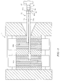
- FIG. 1 is a top or plan view of a four level stack mold in the closed position with the sprue bars engaging the injector nozzle in accordance with the principles of the present invention.
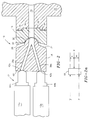
- FIG. 2 is a top or plan and partial cross-sectional view of the nozzle of the present invention being used with two sprue bars.
- FIG. 2a is a schematic diagram of the force distribution associated with the nozzle, sprue bars, and injection molder.
- FIG. 3 is a front elevational view of the nozzle shown in FIG. 2.
- FIG. 4 is an exploded assembly view of the nozzle shown in FIG. 2.
- FIG. 5 is a front elevational view of a nozzle of the present invention showing an alternative embodiment for use with three sprue bars.
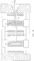
- FIG. 6 shows another alternative embodiment of this invention for use with four sprue bars.
- FIG. 7 shows a front elevational view of the embodiment of the nozzle shown in FIG. 6.
- FIG. 8 is another alternative embodiment of the invention for use with multiple sprues.
- FIG. 9 is another alternative embodiment of the invention for use with a singular set of opposing channels.
- FIG. 10 is a top or plan view of a multi-level stack injection molder of FIG. 1 in the open position.
- FIG. 11 is a top or plan view similar to FIG. 3 showing the nozzle of the present invention adjusting for the non-simultaneous return of the sprue bars.
- FIG. 1 a top or plan view of the nozzle of the instant invention, designated generally as 10, being used with multiple sprue bar arrangement 12 in a stack injection mold 14.
- injector nozzle 10 includes an adapter 16 and a nozzle tip 18.
- Adapter 16 is used for connecting nozzle 10 to the discharge end 20 of a molding resin barrel 22.
- Side 24 of adapter 16 is specifically shaped to engage the barrel 22.
- the adapter is secured to the barrel 22 by bolts or other well known conventional means not shown for clarity.
- Adapter 16 also includes a channel 26 extending therethrough from side 24 to side 28. While being attached with barrel 22, channel 26 is adapted to be in alignment with an output port 29 of barrel 22 for discharging molding resin from barrel 22 through adapter 16 and into nozzle tip 18.
- Side 28 includes an area having a concave recess 30 substantially centered on side 28. Recess 30 engages a mating convex spherical extension 32 extending from side 34 of nozzle tip 18.
- Concave recess 30 is preferably hardened and polished so that it performs as a sealing surface and a sliding surface for the mating convex spherical extension 32 of nozzle tip 18. By being polished and hardened, friction with extension 32 is minimized.
- Convex spherical extension 32 of nozzle tip 18 has a radius that matches concave recess 30 of adapter 16. However, the depth of extension 32 is greater than the depth of recess 30 so that clearance is provided for nozzle tip to pivot relative adapter 16. Side 34 at the locations extending outwardly from the base of extension 32 is substantially angled relative to surface 28 so as also to allow for pivotal movement of side 34 relative side 28. However, any configuration allowing pivoting can be used, such as e.g., cylindrical rather than spherical surfaces.
- convex extension 32 is hardened and polished for establishing a sealing and sliding engagement with concave recess 30.
- inlet 36 is in alignment with channel 26 of adapter 16.
- Inlet 36 extends slightly into the depth of extension 32 and diverges into two channels 38a and 38b.
- Channels 38a and 38b extend through the entire depth of nozzle tip 18 in a diverging manner and open into side 40 of nozzle tip 18.
- channels 38a and 38b lead into two areas having concave recesses 42a and 42b formed into side 40.
- Recesses 42a and 42b are adapted to partially engage the convex ends of sprue bushings 44a and 44b, respectively, of sprue bars 12a and 12b, respectively, as shown in FIG. 2.
- the surfaces of concave recesses 42a and 42b are also hardened and polished for establishing a sealed and sliding relationship with sprue bar bushings 44a and 44b (see FIG. 2), respectively.
- channels 38a and 38b are adapted to be in fluid communication with sprue bars 12a and 12b, respectively, for the flow of molding resin from barrel 22 into adapter 16 through nozzle tip 18 and into the sprue bars 12a and 12b.
- FIG. 2a illustrates how the force exerted by the injection unit or carriage (not shown) is distributed on the nozzle tip of the present invention.
- the sum of forces Y and Z, respectively, from sprue bars 12a and 12b is equal to force X of the injection unit (not shown).
- the lateral distances of sprue bars 12a and 12b, n and m, respectively, of forces Y and Z, respectively, from the point of application of force X are substantially equal, than forces Y and Z will be substantially equal and one half of X.
- one of the distances is zero then the corresponding force will be equal to the force X since force X is acting directly on only one of the sprue bars.
- adapter 16 includes bolt holes (not shown) for mounting to barrel 22 (see FIG. 1) of the injection unit extruder (not shown).
- Convex extension 32 of nozzle tip 18 is inserted into concave recess 30 of adapter 16.
- Nozzle tip 18 includes two bores 48a and 48b aligned with respective bores 46a and 46b and threaded holes 50a and 50b, respectively, of adapter 16 for connecting adapter 16 and nozzle tip 18.
- Flanged sleeves 52a and 52b are inserted into Bellville washers 54a and 54b, respectively, wherein the sleeve and washer assembly is inserted into each of bores 56a and 56b, positioned in side 40 of nozzle tip 18 and which lead into bores 48a and 48b, respectively, such that the large diameters of the Bellville washers 54a and 54b rest on faces 58a and 58b, respectively, of bores 56a and 56b.
- Bolts 60a and 60b are then inserted through sleeves 52a and 52b, respectively, and screwed into the threaded bores 50a and 50b of adapter 18.
- caps 62a and 62b are screwed into threaded counter bores 56a and 56b for the purpose of preventing plastic from entering counter bores 56a and 56b and interfering with the spring operation of washers 54b and 54b.
- Bellville washers 54 serve an important function of maintaining the nozzle tip in axial alignment with the adapters. After pivoting, the springs of the washers force the nozzle tip back to the axially aligned position shown in FIG. 2. Another function of the washers is to exert a force between the adapter and nozzle tip and keep the spherical surfaces of the extensions and recesses seated so there is no leakage at the interface when the nozzle tips are disengaged by the sprue bars.
- FIG. 5 A front elevational view of a second embodiment of the nozzle of the present invention is shown in FIG. 5 as nozzle 110 and is adapted for use with three sprue bars.
- the assembly is essentially the same as shown in FIG. 2 for nozzle 10 except for the addition of a third concave recess 142c along with concave recesses 142a and 142b, for engaging three sprue bars (not shown).
- recesses 142a, 142b and 142c are arranged in a triangular manner on surface 140.
- nozzle 110 The assembly of nozzle 110 is the same as discussed above for nozzle 10 except that instead of using two bolt, sleeve and washer assemblies, three such assemblies are used and arranged in a triangular manner offset from the triangular arrangement of recesses 142a-142c.
- nozzle 110 includes three channels 138a, 138b and 138c which lead to an inlet 136 and a straight channel (not shown) of the adapter (not shown), similar to as described above.
- the nozzle tip of nozzle 110 engages the adapter as described above using mating concave and convex spherical surfaces.
- Nozzle 210 shown in FIGS. 6 and 7 is another alternative embodiment of the present invention. As shown in FIG. 6, nozzle 210 is adapted to be used with four sprue bars 112a-112d. Nozzle 210 includes an adapter 216, pivotal primary nozzle tip 218 and pivotal secondary nozzle tips 219a and 219b. With reference to adapter 216 and primary nozzle tip 218, these elements are similar to as described above for adapter 16 and nozzle tip 18, respectively. One difference in this embodiment, is that adapter 216 and primary nozzle tip 218 are larger in size and consequently, larger in surface area for receiving both of secondary nozzles 219a and 219b on surface 240 of primary nozzle tip 218.
- channel 226 of adapter 216 leads into an inlet 236 of primary nozzle tip 218.
- Inlet 236 branches into two diverging channels 238a and 238b which open up into side 240 and are centered on concave recesses 242a and 242b.
- Nozzle 210 differs from nozzle 10 via the use of a secondary nozzle tips 219a and 219b. Instead of concave recesses 242a and 242b engaging sprue bars, concave recesses 242a and 242b pivotally engage secondary nozzle tips 219a and 219b. Secondary nozzle tips 219a and 219b are simply smaller versions of primary nozzle tip 218, having the same overall design but smaller in size. Accordingly, secondary nozzle tips 219a and 219b include inlets 270a and 270b, respectively, in fluid communication with channels 238a and 238b, respectively, of primary nozzle tip 218.
- Inlets 270a and 270b lead into diverging channels 272a and 272b and 272c and 272d, respectively, which diverge and extend through the body of secondary nozzle tips 219a and 219b, respectively, opening into sides 274a and 274b, respectively.
- Channels 272a and 272b open into concave recesses 276a and 276b, respectively, which are adapted to engage sprue bars 112a and 112b and channels 272c and 272d open into concave recesses 276c and 276d, respectively, and are adapted to engage sprue bars 112c and 112d, respectively.
- Nozzle 310 shown in FIG. 8, is another alternative embodiment of the present invention and is very similar to nozzle 210 with the exception that it is directed for use in correcting axial alignment with nozzles and sprues. As shown in FIG. 8, nozzle 310 is adapted to be used with sprues 378a and 378b. Nozzle 310 includes an adapter 316, pivotal primary nozzle tip 318 and pivotal secondary nozzle tips 319a and 319b.
- adapter 316 and primary nozzle tip 318 are similar to as described above for adapter 16 and nozzle tip 18, respectively, including the spring loaded connections therebetween, as shown in FIG. 4.
- the spring loaded connections are not shown here for clarity.
- adapter 316 and primary nozzle tip 318 are preferably larger in size and consequently, larger in surface area for receiving both of secondary nozzles 319a and 319b on surface 340 of primary nozzle tip 318.
- channel 326 of adapter 316 leads into an inlet 336 of primary nozzle tip 318.
- Inlet 336 branches into two diverging channels 338a and 338b which open up into side 340 and are centered on concave recesses 342a and 342b.
- Nozzle 310 differs from nozzle 10 via the use of a secondary nozzle tips 319a and 319b. Instead of concave recesses 342a and 342b engaging sprue bars, concave recesses 342a and 342b pivotally engage secondary nozzle tips 319a and 319b. Secondary nozzle tips 319a and 319b are smaller versions of primary nozzle tip 318, having the same overall design with exception of the diverging channels. Accordingly, secondary nozzle tips 319a and 319b include channels 370a and 370b, respectively, in fluid communication with channels 338a and 338b, respectively, of primary nozzle tip 318. Channels 370a and 370b extend longitudinally straight through secondary nozzle tips 319a and 319b, respectively.
- Channels 370a and 370b open into concave recesses 376a and 376b, respectively, which are adapted to engage sprue bushings 378a and 378b.
- all surfaces of concave recesses and convex extensions are polished and hardened so as to achieve a sealable and slidable engagements therebetween.
- Recesses 376a and 376b are adapted to engage sprues 378a and 378b, respectively, wherein the spherical surfaces of the bushings and the recesses have matching radii.
- the force exerted by the carriage (not shown) is all that is needed to effectively create the necessary seal between the mating surfaces.
- the application of the nozzle disclosed in this invention is not limited to simply two, three or four sprue bars.
- An apparatus can be designed and adapted to effectively engage any number of sprue bars, as required by the design of the injection mold.
- any number of sprue bars can be connected with the nozzles of the present invention, wherein each receives an individual sealing force.
- the nozzle of the instant invention can be used with only one sprue or sprue bar.
- FIG. 9 shows an embodiment of the present invention adapted to be used with only two channels, i.e, between a sprue and the adapter 410, wherein axial misalignment is compensated thereby but force equalization is not a feature.
- This embodiment includes an adapter 416, a nozzle tip 418, and a sprue 480.
- Nozzle tip 418 is connected to adapter 416 via the resilient spring loaded connections discussed for the main embodiment and shown in FIG. 4.
- Adapter 416 is substantially the same as that discussed above, having an inlet channel 426 and a substantially concave recess 482 for engagement with a convex extension 483 of the nozzle tip.
- nozzle tip 418 is connected to the adapter as discussed earlier but the nozzle tip has only one channel 438 extending longitudinally through it. Since only one channel is connected to one sprue, force equalization is not an issue.
- the sprue 480 also has a concave recess 484 for engagement with another convex extension 485 of the nozzle tip.
- nozzle tip 418 includes two convex extensions with a body portion therebetween, wherein the wall 486 of the body portion, adjacent adapter 416, is angled on each side of extension 483, from the extension away from the adapter.
- the angling of wall 486 allows for the pivotal movement of nozzle tip 418 relative to adapter 416 and sprue 480.
- Such pivoting between the interfaces facilitates alignment and the creation of a seal between the barrel (not shown) and sprue via the axial force pushing them together.
- Substantial misalignment can be tolerated, as shown in FIG. 9, by assuring via the design of nozzle tip 418, that the walls 486 and 487 of nozzle tip 418 are substantially distanced from the walls 488 and 490, respectively, of adapter 416 and sprue 480 to allow substantial pivoting.
- sprue bars 12a and 12b move with hot runners 80a and 80b. Due to the length of sprue bars 12a and 12b and normal mechanical variations, sprue bushings 44a and 44b tend not to return to the exact same location each time the injection mold is closed. Unlike the prior art, where systems allow very little variation in the return positioning of the sprue bushings to function properly, and require extremely precise manufacturing of the components comprising the system including the sprue bars, sprue bushings and nozzle tips, the instant device is return position error tolerant and does not require precision manufacturing.
- the instant invention compensates for these variations and distributes the forces exerted by the injection unit to the sprue bars in a desired manner, as shown earlier in FIG. 2a. Therefore, none of the parts comprising the instant invention have to be manufactured to high precision.
- the pair of cooperating spherical surfaces, recess 30 and extension 32 of adapter 16 and nozzle tip 18, respectively slide on each other to allow nozzle tip 18 to pivot until all pairs of cooperating spherical surfaces are in contact before any significant force is exerted by the injection unit carriage on the sprue bars.
- sprue bushings 44a and 44b with recesses 42a and 42b, respectively forces of the injection carriage will be distributed as described in FIG. 2a.
- FIG. 11 illustrates an extreme case for the FIG. 1 embodiment where sprue bushings 44a and 44b are positioned at substantially different longitudinal positions upon return to the nozzle tip. This difference is shown as distance A. Accordingly, sprue bush 44a is in contact with its cooperating concave surface of recess 42a and sprue bush 44b is a distance A from contacting the concave spherical surface of its respective recess 42b.
- sprue bar 12a and sprue bush 44a push on the concave spherical surface of recess 42a causing nozzle tip 18 to pivot in the area of engagement between spherical extension 32 of nozzle tip 18 and spherical recess 30 of adapter 16.
- sprue bush 44a is caused to slide on and pivot with recess 42a resulting in concave recess 42b moving toward sprue bush 44b until they contact as shown in FIG. 2.
- This nozzle arrangement will function as described whether the injection unit moves toward the sprue bars or if the sprue bars are moved toward the nozzle and injection unit.
- the description of the operation for nozzle 10 is equally applicable to nozzle 110 and nozzles 210.
- the primary advantage of this invention is that an injector nozzle is provided for use with at least one sprue which distributes a sealing force in a desired manner among at least one or a plurality of sprues and allows for return positioning error. Another advantage is that an injector nozzle is provided for use with at least one sprue which does not require precision manufacturing yet still tolerates substantial misalignment. Still another advantage is that an injector nozzle is provided for use with at least one sprue which requires no modifications to the existing injection molding machines for using the nozzle. Yet another advantage of this invention is that an injector nozzle is provided for use with multiple sprue bars which is tolerant of wear of mating spherical surfaces.
- an injector nozzle for use with multiple sprue bars is provided which can be used in stacked formations to service injection molding machines having almost any number of channels.
- an injector nozzle is provided for use with multiple sprue bars having a simple mechanical operation for insuring equal force distribution to multiple sprue bar arrangements while also assuring uniform sealing forces.
Landscapes
- Engineering & Computer Science (AREA)
- Manufacturing & Machinery (AREA)
- Mechanical Engineering (AREA)
- Injection Moulding Of Plastics Or The Like (AREA)
- Moulds For Moulding Plastics Or The Like (AREA)
- Diaphragms For Electromechanical Transducers (AREA)
- Percussion Or Vibration Massage (AREA)
Applications Claiming Priority (2)
| Application Number | Priority Date | Filing Date | Title |
|---|---|---|---|
| US08/327,561 US5522720A (en) | 1994-10-24 | 1994-10-24 | Injector nozzle with pivotally movable surfaces |
| US327561 | 1994-10-24 |
Publications (2)
| Publication Number | Publication Date |
|---|---|
| EP0709174A1 true EP0709174A1 (de) | 1996-05-01 |
| EP0709174B1 EP0709174B1 (de) | 1999-07-14 |
Family
ID=23277063
Family Applications (1)
| Application Number | Title | Priority Date | Filing Date |
|---|---|---|---|
| EP95116319A Expired - Lifetime EP0709174B1 (de) | 1994-10-24 | 1995-10-17 | Spritzgiessdüse |
Country Status (5)
| Country | Link |
|---|---|
| US (1) | US5522720A (de) |
| EP (1) | EP0709174B1 (de) |
| JP (1) | JP2683231B2 (de) |
| AT (1) | ATE182104T1 (de) |
| DE (1) | DE69510751T2 (de) |
Cited By (3)
| Publication number | Priority date | Publication date | Assignee | Title |
|---|---|---|---|---|
| EP1300232A1 (de) * | 2001-10-04 | 2003-04-09 | Quaser S.r.L | Heisskanal - Düsenkombination für Kunststoffspritzgiesswerkzeuge |
| EP1488905A1 (de) * | 2003-06-20 | 2004-12-22 | Mold-Masters Limited | Heisskanalverteiler mit mehrachsig justierbaren Verteilerblöcken und Düsen |
| AT523516A4 (de) * | 2020-07-08 | 2021-09-15 | Engel Austria Gmbh | Einspritzanordnung für eine Formgebungsmaschine und Verfahren zum Betreiben einer solchen |
Families Citing this family (19)
| Publication number | Priority date | Publication date | Assignee | Title |
|---|---|---|---|---|
| US5968562A (en) * | 1997-09-24 | 1999-10-19 | Husky Injection Molding Systems, Ltd. | Sprue bar assembly for use in a stack mold |
| US5910327A (en) * | 1997-09-24 | 1999-06-08 | Husky Injection Molding Systems | Sprue bar assembly for a stack mold |
| US6726467B1 (en) * | 2002-10-16 | 2004-04-27 | R&D Tool & Engineering Co. | Injection molding nozzle |
| US8128397B2 (en) * | 2004-04-09 | 2012-03-06 | Injectnotech Inc. | Cross-over nozzle system for stack molds |
| US7261553B2 (en) | 2004-04-09 | 2007-08-28 | Injectnotech Inc. | Crossover nozzle system for stack molds |
| US7658607B2 (en) * | 2004-04-09 | 2010-02-09 | Injectnotech Inc. | Cross-over nozzle system for stack molds |
| DE102004049361A1 (de) * | 2004-10-08 | 2006-04-13 | Demag Ergotech Gmbh | Spritzgießmaschine mit nachrüstbarer Einspritzeinheit und Nachrüstmodul für eine solche Spritzgießmaschine |
| US7232538B2 (en) * | 2004-10-15 | 2007-06-19 | Husky Injection Molding Systems Ltd. | Injection molding coupling apparatus |
| US7393479B2 (en) * | 2004-10-15 | 2008-07-01 | Husky Injection Molding Systems Ltd. | Injection molding three-way shut off valve |
| US7284979B2 (en) * | 2004-10-15 | 2007-10-23 | Husky Injection Molding Systems Ltd. | Self aligning articulated joint for use in a hot runner system |
| US7704069B2 (en) * | 2005-12-20 | 2010-04-27 | R&D Tool & Engineering Co. | Injection molding apparatus having swiveling nozzles |
| US20080029932A1 (en) * | 2006-08-02 | 2008-02-07 | Shape Corporation | Molding machine with platen-attached hot runner manifold |
| US20080131547A1 (en) * | 2006-11-30 | 2008-06-05 | Husky Injection Molding Systems Ltd. | External Sprue Bar Position Alignment Apparatus |
| US7771189B2 (en) | 2008-03-03 | 2010-08-10 | R&D Tool & Engineering Co. | Injection molding apparatus with replaceable gate insert |
| CA2819908C (en) | 2010-12-20 | 2014-05-06 | Mold Hotrunner Solutions Inc. | Melt distribution manifold |
| WO2012092658A1 (en) | 2011-01-09 | 2012-07-12 | Husky Injection Molding Systems Ltd. | Melt-delivery assembly including frame assembly positioned outside of platen envelope, and having multiple-outlet assembly |
| DE102014018794A1 (de) * | 2014-12-19 | 2016-06-23 | Gebr. Krallmann Gmbh | Metallspritzdüse zum Spritzgießen einer flüssigen Metall-Komponente |
| DE102014018793A1 (de) * | 2014-12-19 | 2016-06-23 | Gebr. Krallmann Gmbh | Metallspritzdüse zum Spritzgießen einer flüssigen Metall-Komponente |
| JP7155937B2 (ja) * | 2018-11-22 | 2022-10-19 | セイコーエプソン株式会社 | 三次元造形装置および三次元造形装置の制御方法 |
Citations (9)
| Publication number | Priority date | Publication date | Assignee | Title |
|---|---|---|---|---|
| US2871517A (en) * | 1955-08-31 | 1959-02-03 | Improved Machinery Inc | Injection molding machine nozzle |
| GB1062169A (en) * | 1964-10-15 | 1967-03-15 | Desma Werke Gmbh | Improvements in nozzles for injecting resilient materials into injection moulds |
| DE1554847A1 (de) * | 1966-01-25 | 1970-01-29 | Phoenix Gummiwerke Ag | Spritzgiessmaschine mit federnd beweglicher Duesenkappe |
| BE770093R (en) * | 1971-07-15 | 1972-01-17 | Ryck Petrus R De | Extrusion head - with die with cylindrical end fitting into cavity in connection piece for filling moulds with plastics material |
| US3843295A (en) | 1973-05-24 | 1974-10-22 | Bischoff Chemical Corp | Injection molding machine with adjustable nozzle length means |
| US3915610A (en) | 1974-04-10 | 1975-10-28 | Arthur Kohler | Alignment assemblies for plastic injection molds |
| JPS55139237A (en) * | 1979-04-17 | 1980-10-30 | Toyoda Gosei Co Ltd | Nozzle device of injection molding machine |
| US4299791A (en) | 1979-07-18 | 1981-11-10 | Katashi Aoki | Method for the prevention of drooling from a plastic injection molding mold and injection nozzles |
| US4917595A (en) | 1988-06-01 | 1990-04-17 | Sankyo Engineering Co., Ltd. | Nozzle touch sprue bushing device |
Family Cites Families (3)
| Publication number | Priority date | Publication date | Assignee | Title |
|---|---|---|---|---|
| US3568256A (en) * | 1968-07-15 | 1971-03-09 | J & J Machine Co Inc | Plastic feeder head |
| US5229145A (en) * | 1990-06-27 | 1993-07-20 | David Brown | Multi-level stacked mold system |
| US5370523A (en) * | 1993-08-16 | 1994-12-06 | Dollins Tool, Inc. | Triple stack molding arrangement |
-
1994
- 1994-10-24 US US08/327,561 patent/US5522720A/en not_active Expired - Lifetime
-
1995
- 1995-10-17 AT AT95116319T patent/ATE182104T1/de not_active IP Right Cessation
- 1995-10-17 DE DE69510751T patent/DE69510751T2/de not_active Expired - Fee Related
- 1995-10-17 EP EP95116319A patent/EP0709174B1/de not_active Expired - Lifetime
- 1995-10-24 JP JP7276016A patent/JP2683231B2/ja not_active Expired - Fee Related
Patent Citations (9)
| Publication number | Priority date | Publication date | Assignee | Title |
|---|---|---|---|---|
| US2871517A (en) * | 1955-08-31 | 1959-02-03 | Improved Machinery Inc | Injection molding machine nozzle |
| GB1062169A (en) * | 1964-10-15 | 1967-03-15 | Desma Werke Gmbh | Improvements in nozzles for injecting resilient materials into injection moulds |
| DE1554847A1 (de) * | 1966-01-25 | 1970-01-29 | Phoenix Gummiwerke Ag | Spritzgiessmaschine mit federnd beweglicher Duesenkappe |
| BE770093R (en) * | 1971-07-15 | 1972-01-17 | Ryck Petrus R De | Extrusion head - with die with cylindrical end fitting into cavity in connection piece for filling moulds with plastics material |
| US3843295A (en) | 1973-05-24 | 1974-10-22 | Bischoff Chemical Corp | Injection molding machine with adjustable nozzle length means |
| US3915610A (en) | 1974-04-10 | 1975-10-28 | Arthur Kohler | Alignment assemblies for plastic injection molds |
| JPS55139237A (en) * | 1979-04-17 | 1980-10-30 | Toyoda Gosei Co Ltd | Nozzle device of injection molding machine |
| US4299791A (en) | 1979-07-18 | 1981-11-10 | Katashi Aoki | Method for the prevention of drooling from a plastic injection molding mold and injection nozzles |
| US4917595A (en) | 1988-06-01 | 1990-04-17 | Sankyo Engineering Co., Ltd. | Nozzle touch sprue bushing device |
Non-Patent Citations (1)
| Title |
|---|
| PATENT ABSTRACTS OF JAPAN vol. 5, no. 6 (M - 50)<678> 16 January 1981 (1981-01-16) * |
Cited By (6)
| Publication number | Priority date | Publication date | Assignee | Title |
|---|---|---|---|---|
| EP1300232A1 (de) * | 2001-10-04 | 2003-04-09 | Quaser S.r.L | Heisskanal - Düsenkombination für Kunststoffspritzgiesswerkzeuge |
| EP1488905A1 (de) * | 2003-06-20 | 2004-12-22 | Mold-Masters Limited | Heisskanalverteiler mit mehrachsig justierbaren Verteilerblöcken und Düsen |
| US7172411B2 (en) | 2003-06-20 | 2007-02-06 | Mold-Masters Limited | Injection molding manifold with multi-axis adjustable manifold blocks and nozzles |
| AT523516A4 (de) * | 2020-07-08 | 2021-09-15 | Engel Austria Gmbh | Einspritzanordnung für eine Formgebungsmaschine und Verfahren zum Betreiben einer solchen |
| AT523516B1 (de) * | 2020-07-08 | 2021-09-15 | Engel Austria Gmbh | Einspritzanordnung für eine Formgebungsmaschine und Verfahren zum Betreiben einer solchen |
| US11969927B2 (en) | 2020-07-08 | 2024-04-30 | Engel Austria Gmbh | Injection arrangement for a moulding machine and method for operating the same |
Also Published As
| Publication number | Publication date |
|---|---|
| DE69510751D1 (de) | 1999-08-19 |
| US5522720A (en) | 1996-06-04 |
| JPH08252839A (ja) | 1996-10-01 |
| ATE182104T1 (de) | 1999-07-15 |
| EP0709174B1 (de) | 1999-07-14 |
| DE69510751T2 (de) | 2000-04-06 |
| JP2683231B2 (ja) | 1997-11-26 |
Similar Documents
| Publication | Publication Date | Title |
|---|---|---|
| US5522720A (en) | Injector nozzle with pivotally movable surfaces | |
| EP0873841B1 (de) | Spritzgiessdüse mit einteiligem Einspritzöffnungseinsatz zum Halten eines zylindrischen Ventils | |
| US5334010A (en) | Valve gated injection molding apparatus with a spring in the piston | |
| KR101138473B1 (ko) | 보정 몰드 스택 및 정렬 방법 | |
| US6921259B2 (en) | Valve pin guide for a valve-gated nozzle | |
| KR101138587B1 (ko) | 몰딩 시스템과 함께 사용하기 위한 보정 코어 및 보정 코어를 포함하는 몰딩 시스템 | |
| US7850442B2 (en) | Edge-gated nozzle | |
| KR101146046B1 (ko) | 보정 몰드 스택, 이를 포함하는 몰딩 시스템 및 보정 몰드 스택을 정렬시키는 방법 | |
| US6860732B2 (en) | Thermal seal between manifold and nozzle | |
| CA2473921C (en) | Gate assembly for reducing drooling of melt from a sprue bar | |
| KR101086606B1 (ko) | 몰딩 시스템과 함께 사용하기 위한 보정 유지 부재 및 이를 포함하는 몰딩 시스템 | |
| EP2002951B1 (de) | Keilsperrsystem für Sptitzgiessformen | |
| CA2180602C (en) | Four heated nozzle manifolds interconnected in a common plane | |
| US7416402B2 (en) | Sprue bushing anti-drool device | |
| US7320590B2 (en) | Manifold plug for an injection molding apparatus | |
| US7284979B2 (en) | Self aligning articulated joint for use in a hot runner system | |
| US7850895B2 (en) | Sprue bar shutoff method | |
| US7678320B2 (en) | Anti-drool mechanism for a sprue bushing | |
| US20060182842A1 (en) | Nozzle and apparatus for injection molding | |
| JP2009515731A (ja) | 射出成型用ノズルおよび装置 | |
| US3561062A (en) | Injection molding nozzle with flow-control mechanism | |
| US7220117B2 (en) | Nozzle and apparatus for injection molding | |
| US7455515B2 (en) | Nozzle and apparatus for injection molding | |
| USRE39935E1 (en) | Multi-cavity injection molding apparatus splitting melt near nozzle front | |
| CA2861309C (en) | Hot runner with removable gate pad |
Legal Events
| Date | Code | Title | Description |
|---|---|---|---|
| PUAI | Public reference made under article 153(3) epc to a published international application that has entered the european phase |
Free format text: ORIGINAL CODE: 0009012 |
|
| AK | Designated contracting states |
Kind code of ref document: A1 Designated state(s): AT DE FR GB IT |
|
| 17P | Request for examination filed |
Effective date: 19960502 |
|
| 17Q | First examination report despatched |
Effective date: 19970604 |
|
| RIN1 | Information on inventor provided before grant (corrected) |
Inventor name: SZAJAK, JERZY Inventor name: SCHAD, ROBERT D. |
|
| GRAG | Despatch of communication of intention to grant |
Free format text: ORIGINAL CODE: EPIDOS AGRA |
|
| GRAG | Despatch of communication of intention to grant |
Free format text: ORIGINAL CODE: EPIDOS AGRA |
|
| GRAH | Despatch of communication of intention to grant a patent |
Free format text: ORIGINAL CODE: EPIDOS IGRA |
|
| GRAH | Despatch of communication of intention to grant a patent |
Free format text: ORIGINAL CODE: EPIDOS IGRA |
|
| GRAA | (expected) grant |
Free format text: ORIGINAL CODE: 0009210 |
|
| AK | Designated contracting states |
Kind code of ref document: B1 Designated state(s): AT DE FR GB IT |
|
| REF | Corresponds to: |
Ref document number: 182104 Country of ref document: AT Date of ref document: 19990715 Kind code of ref document: T |
|
| REF | Corresponds to: |
Ref document number: 69510751 Country of ref document: DE Date of ref document: 19990819 |
|
| ET | Fr: translation filed | ||
| ITF | It: translation for a ep patent filed | ||
| PLBE | No opposition filed within time limit |
Free format text: ORIGINAL CODE: 0009261 |
|
| STAA | Information on the status of an ep patent application or granted ep patent |
Free format text: STATUS: NO OPPOSITION FILED WITHIN TIME LIMIT |
|
| 26N | No opposition filed | ||
| REG | Reference to a national code |
Ref country code: GB Ref legal event code: IF02 |
|
| PGFP | Annual fee paid to national office [announced via postgrant information from national office to epo] |
Ref country code: FR Payment date: 20080828 Year of fee payment: 14 |
|
| PGFP | Annual fee paid to national office [announced via postgrant information from national office to epo] |
Ref country code: GB Payment date: 20080829 Year of fee payment: 14 |
|
| PGFP | Annual fee paid to national office [announced via postgrant information from national office to epo] |
Ref country code: DE Payment date: 20080828 Year of fee payment: 14 |
|
| PGFP | Annual fee paid to national office [announced via postgrant information from national office to epo] |
Ref country code: AT Payment date: 20080828 Year of fee payment: 14 |
|
| PGFP | Annual fee paid to national office [announced via postgrant information from national office to epo] |
Ref country code: IT Payment date: 20081008 Year of fee payment: 14 |
|
| REG | Reference to a national code |
Ref country code: FR Ref legal event code: ST Effective date: 20100630 |
|
| PG25 | Lapsed in a contracting state [announced via postgrant information from national office to epo] |
Ref country code: FR Free format text: LAPSE BECAUSE OF NON-PAYMENT OF DUE FEES Effective date: 20091102 Ref country code: DE Free format text: LAPSE BECAUSE OF NON-PAYMENT OF DUE FEES Effective date: 20100501 |
|
| PG25 | Lapsed in a contracting state [announced via postgrant information from national office to epo] |
Ref country code: AT Free format text: LAPSE BECAUSE OF NON-PAYMENT OF DUE FEES Effective date: 20091017 |
|
| PG25 | Lapsed in a contracting state [announced via postgrant information from national office to epo] |
Ref country code: GB Free format text: LAPSE BECAUSE OF NON-PAYMENT OF DUE FEES Effective date: 20091017 |
|
| PG25 | Lapsed in a contracting state [announced via postgrant information from national office to epo] |
Ref country code: IT Free format text: LAPSE BECAUSE OF NON-PAYMENT OF DUE FEES Effective date: 20091017 |