EP0709181B1 - Drehbare Vorrichtung zum Freisetzen des Balles in Ballenpressen und Verfahren zum Verpressen zu Ballen - Google Patents
Drehbare Vorrichtung zum Freisetzen des Balles in Ballenpressen und Verfahren zum Verpressen zu Ballen Download PDFInfo
- Publication number
- EP0709181B1 EP0709181B1 EP95112211A EP95112211A EP0709181B1 EP 0709181 B1 EP0709181 B1 EP 0709181B1 EP 95112211 A EP95112211 A EP 95112211A EP 95112211 A EP95112211 A EP 95112211A EP 0709181 B1 EP0709181 B1 EP 0709181B1
- Authority
- EP
- European Patent Office
- Prior art keywords
- gate member
- bale
- exit passageway
- charging
- compression chamber
- Prior art date
- Legal status (The legal status is an assumption and is not a legal conclusion. Google has not performed a legal analysis and makes no representation as to the accuracy of the status listed.)
- Expired - Lifetime
Links
- 230000007246 mechanism Effects 0.000 title claims description 25
- 238000000034 method Methods 0.000 title claims 3
- 230000006835 compression Effects 0.000 claims description 39
- 238000007906 compression Methods 0.000 claims description 39
- 239000000463 material Substances 0.000 claims description 22
- 239000002699 waste material Substances 0.000 description 7
- 235000013361 beverage Nutrition 0.000 description 1
- 238000010276 construction Methods 0.000 description 1
- 230000000694 effects Effects 0.000 description 1
- 238000012986 modification Methods 0.000 description 1
- 230000004048 modification Effects 0.000 description 1
- 239000010813 municipal solid waste Substances 0.000 description 1
Images


Classifications
-
- B—PERFORMING OPERATIONS; TRANSPORTING
- B30—PRESSES
- B30B—PRESSES IN GENERAL
- B30B9/00—Presses specially adapted for particular purposes
- B30B9/30—Presses specially adapted for particular purposes for baling; Compression boxes therefor
- B30B9/3003—Details
- B30B9/3014—Ejection means
Definitions
- the compression ram head will on occasion move too much material into the compression chamber where the bale is formed so that the material protrudes back from the compression chamber into the charging passage which leads from the charging chamber to the compression chamber. Such a situation may occur, for example, if an excessive amount of material is originally charged into the bale charging chamber. Under such a condition, the compression ram head cannot be advanced to its normal baling eject position, i.e., with the base of the compression ram head in alignment with the side wall of the discharge passage from the compression chamber through which the bale is ejected.
- the width of the bale will be greater than that of the discharge passage and thus the oversized bale cannot be ejected through the discharge passage by the ejector ram head.
- such an oversized bale condition can be remedied only by a manual removal of the excess material in the baling chamber to thereby reduce the size of the oversized bale. Such a manual removal operation is time-consuming.
- the bale release mechanism of the present invention contemplates a design wherein the exit passageway size can be increased to accommodate oversized bales of various size.
- the mechanism is relatively simple and less costly than prior mechanisms. Other advantages will be apparent from the description which follows.
- a baler machine comprising a charging chamber for receiving material to be baled, said charging chamber having a charging passageway through which material is forced into a baling compression chamber by a compression ram.
- An ejector ram is provided for forcing compressed material in bale form out of the baling compression chamber through an exit passageway.
- a rotatable bale release mechanism is provided which, upon actuation, will increase the effective size of the exit passageway from the compression chamber.
- a power means is provided to pivot the release mechanism from a normal operating position to a second position wherein the effective size of the exit passageway is increased to permit the ejection of an oversized bale from the compression chamber should such a condition be encountered.
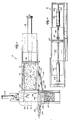
- baler machine 10 is designed for baling waste material such as paper, cardboard, corrugated containers, used beverage cases, municipal solid waste, etc.
- Machine 10 has a charging chamber 12 into which waste material is loaded.
- the charging chamber 12 is generally rectangular in horizontal section having a flat floor and opposed side walls 16.
- the baler machine 10 includes a hydraulic compression cylinder 18 having a compression ram head 20 which is movable horizontally in the charging chamber 12.
- the charging chamber 12 communicates with a compression chamber 22 through a charging passage 30.
- the waste material is compressed from the charging chamber 12 into the compression chamber 22 by the forward movement of compression ram head 20.
- the baler machine 10 further includes a bale ejection cylinder 34 having an ejection ran, head 32.
- the compression chamber 22 is provided with a exit passageway 38.
- a bale release mechanism 40 is mounted at one side of the exit passageway 38.
- the mechanism is comprised of a rotatably mounted gate member 42 comprised of a face member 44 and an arm member 46.
- the arm member 46 is pivotally mounted at a pivot means 48 of any suitable design.
- Gate member 42 is rotated between a closed position (Figs. 3, 4, 7) and an open position (Figs. 5, 6) by a hydraulic cylinder 50.
- Cylinder 50 is pivotally connected at one end 52 to a stationary support 54.
- the power actuator rod 56 of the cylinder 40 is pivotally connected to the exterior surface of the face member 40 as indicated by reference numeral 58.
- a bale strapping apparatus of suitable design (not shown) is mounted in the area into which the bales are ejected by ejector head 32.
- An exit gate mechanism 60 is mounted in the exit passageway 38.
- the mechanism is comprised of a slidable gate member 62 which is movable between an open position (Figs. 5, 6) and a closed position (Figs. 3, 4, 7) by a hydraulic exit gate cylinder 64.
- the charging ram head 20 stops in advanced position substantially flush with the corresponding side or edge of the ejection ram head 32 as shown in Fig. 3 to thereby produce a standard sized bale 41.
- the ejection ram head 32 is then advanced step-by-step to push the material out of the baling chamber 22 through the exit passage 38.
- the compressed material in its bale shape is tied by a strapping mechanism of conventional design (not shown). At each pause between incremental advances of the ram 32, the ejected material is tied with an encircling strap or wire by the strapping mechanism located just outside the exit passage 38.
- the gate 62 is moved from its open to its closed position by energization of cylinder 64. Compression of material in chamber 22 and ejection therefrom is thus repeated to form subsequent standard sized bales.
- the problem to which this invention is directed is a situation where an excess of waste material is charged into the baling chamber 22.
- the compression ram head 20 is unable to push the last charge of material completely out of the charging passage 30 into the baling compression chamber 22.
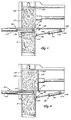
- the condition is shown in Fig. 4, wherein a portion 43 of the charge in the chamber 22 protrudes back into the charging passage 30, resulting in an over sized bale 45. It is difficult, if not impossible, to eject the over-sized bale 45 out of the chamber 22 through the exit passage 38 by the operation of the ejection ram head 32. A time-consuming manual clearing of the excess material would be required absent the operation of the present invention.
- bale release mechanism 40 shown in Figs. 4, 5, 6 and 7.
- gate member 42 is retracted by cylinder 50 from the position shown in Fig. 4 to the position shown in Fig. 5.
- Slidable exit gate member 62 is moved from its closed position (Fig. 4) to its open position (Fig. 5) by exit gate cylinder 64.
- Bale release mechanism 40 is then actuated back to its closed position and gate mechanism 60 is also actuated to its closed position as shown in Fig. 7. The bale forming operation can then continue.
Landscapes
- Engineering & Computer Science (AREA)
- Mechanical Engineering (AREA)
- Basic Packing Technique (AREA)
- Auxiliary Devices For And Details Of Packaging Control (AREA)
Claims (7)
- Ballenpresse mit:(a) einer Beladungskammer (12) zum Aufnehmen von zu pressendem Material, wobei die Beladungskammer einen Beladungsdurchgang (30) aufweist;(b) einer Ballenpreßkammer (22), die mit der Beladungskammer über den Beladungsdurchgang in Verbindung steht, wobei die Ballenpreßkammer einen Austrittsdurchgang (38) aufweist;(c) einer Preßstempeleinrichtung (18, 20), die betreibbar ist, um Material aus der Beladungskammer in die Ballenpreßkammer durch den Beladungsdurchgang zu pressen und dabei das Material in der Ballenpreßkammer zu komprimieren;(d) einer Ausstoßstempeleinrichtung (32, 34) zum Drücken von komprimiertem Material aus der Ballenpreßkammer durch den Austrittsdurchgang;(e) einem Ballenfreigabemechanismus (40), der angrenzend an den Austrittsdurchgang angebracht ist, wobei der Ballenfreigabemechanismus ein drehbar angebrachtes Schieberelement ist, das zwischen einer normal arbeitenden geschlossenen Stellung, in der die Größe des Austrittsdurchgangs einen Durchtritt von Ballen in Standardgröße ermöglicht, und einer zurückgezogenen Stellung, in der die Größe des Austrittsdurchgangs vergrößert ist, um einen Durchtritt von Ballen in Übergröße zu ermöglichen, bewegbar ist;(f) einer Antriebseinrichtung (50), die mit dem Ballenfreigabemechanismus wirkverbunden ist, um den Ballenfreigabemechanismus zwischen seiner geschlossenen und seiner zurückgezogenen Stellung zu bewegen.
- Ballenpresse gemäß Anspruch 1, in der das drehbar angebrachte Schieberelement (42) ein Flächenelement (44) und ein Armelement (46) umfaßt, wobei das Armelement schwenkbar an einem Ende von diesem angeordnet ist.
- Ballenpresse gemäß Anspruch 1, in der ein Austrittsschieber (62) vorhanden ist, der in dem Austrittsdurchgang (38) angebracht ist, wobei der Austrittsschieber zwischen einer geschlossenen Stellung und einer geöffneten Stellung bewegbar ist, wobei der Austrittsdurchgang blockiert ist, wenn der Schieber in der geschlossenen Stellung ist, und der Austrittsdurchgang geöffnet ist, wenn der Schieber in seiner geöffneten Stellung ist.
- Ballenpresse mit einer Beladungskammer (12) zum Aufnehmen von zu einem Ballen zu pressenden Material, einer Preßkammer (22), die mit der Beladungskammer durch einen Beladungsdurchgang (30) in Verbindung steht, einem Preßstempel (18, 20), der bedienbar ist, um Material aus der Beladungskammer in die Preßkammer zu drücken, einem Ausstoßstempel (32, 34) zum Drücken von komprimiertem Material aus der Preßkammer durch einen Austrittsdurchgang (38), wobei die Verbesserung umfaßt:(a) ein drehbar angebrachtes Schieberelement (42), das angrenzend an den Austrittsdurchgang angebracht ist, wobei das Schieberelement zwischen einer normal arbeitenden geschlossenen Stellung und einer zurückgezogenen, geöffneten Stellung drehbar ist, wobei das Schieberelement, wenn es sich in seiner zurückgezogenen Stellung befindet, wirksam die Größe des Austrittsdurchgangs vergrößert;(b) eine Antriebseinrichtung (50), die mit dem drehbar angebrachten Schieberelement wirkverbunden ist und bedienbar ist, um den Schieber zwischen seiner normal arbeitenden geschlossenen Stellung und seiner zurückgezogenen Stellung zu bewegen.
- Ballenpresse gemäß Anspruch 4, in der ein drehbar angebrachtes Schieberelement (42) ein Flächenelement (44) und ein Armelement (46) umfaßt, wobei das Armelement an einem Ende mit dem Flächenelement verbunden ist und drehbar an seinem anderen Ende befestigt ist.
- Verfahren zum Formen von Ballen, welches die Schritte umfaßt:(a) Laden von Material in eine Beladungskammer;(b) Drücken des Materials in der Beladungskammer in eine Ballenpreßkammer, um dabei einen Ballen zu formen, wobei die Ballenpreßkammer einen Austrittsdurchgang aufweist, durch den Ballen ausgestoßen werden;(c) ein drehbar angebrachtes Schieberelement, das angrenzend an den Austrittsdurchgang angebracht ist, wobei das Schieberelement zwischen einer normal arbeitenden Stellung und einer zurückgezogenen offenen Stellung bewegbar ist, Bewegen des Schieberelementes von seiner geschlossenen Stellung zu seiner geöffneten Stellung, um dabei die Größe des Austrittsdurchgangs zu vergrößern, und den Ausstoß von Ballen mit Übergröße aus der Beladungskammer zu ermöglichen; und(d) Ausstoßen eines Ballens mit Übergröße durch den Austrittsdurchgang der Ballenpreßkammer.
- Verfahren zum Formen von Ballen gemäß Anspruch 6, in welchen ein Schieber an dem Preßkammeraustrittsdurchgang bewegbar angebracht ist, wobei der Schieber zwischen einer geschlossenen Stellung und einer geöffneten Stellung bewegbar ist, wobei der Schieber angepaßt ist, um von einer geschlossenen zu einer geöffneten Stellung bewegt zu werden, um ein Ausstoßen eines Ballens aus der Preßkammer zu ermöglichen.
Priority Applications (1)
| Application Number | Priority Date | Filing Date | Title |
|---|---|---|---|
| EP98111998A EP0878293A1 (de) | 1994-10-17 | 1995-08-03 | Drehbare Vorrichtung zum Freisetzen des Ballens in Ballenpressen und Verfahren zum Ballenpressen |
Applications Claiming Priority (2)
| Application Number | Priority Date | Filing Date | Title |
|---|---|---|---|
| US323971 | 1994-10-17 | ||
| US08/323,971 US5463944A (en) | 1994-10-17 | 1994-10-17 | Rotatable bale release mechanism for a baler machine and method of baling |
Related Child Applications (1)
| Application Number | Title | Priority Date | Filing Date |
|---|---|---|---|
| EP98111998A Division EP0878293A1 (de) | 1994-10-17 | 1995-08-03 | Drehbare Vorrichtung zum Freisetzen des Ballens in Ballenpressen und Verfahren zum Ballenpressen |
Publications (2)
| Publication Number | Publication Date |
|---|---|
| EP0709181A1 EP0709181A1 (de) | 1996-05-01 |
| EP0709181B1 true EP0709181B1 (de) | 1998-10-28 |
Family
ID=23261511
Family Applications (2)
| Application Number | Title | Priority Date | Filing Date |
|---|---|---|---|
| EP98111998A Withdrawn EP0878293A1 (de) | 1994-10-17 | 1995-08-03 | Drehbare Vorrichtung zum Freisetzen des Ballens in Ballenpressen und Verfahren zum Ballenpressen |
| EP95112211A Expired - Lifetime EP0709181B1 (de) | 1994-10-17 | 1995-08-03 | Drehbare Vorrichtung zum Freisetzen des Balles in Ballenpressen und Verfahren zum Verpressen zu Ballen |
Family Applications Before (1)
| Application Number | Title | Priority Date | Filing Date |
|---|---|---|---|
| EP98111998A Withdrawn EP0878293A1 (de) | 1994-10-17 | 1995-08-03 | Drehbare Vorrichtung zum Freisetzen des Ballens in Ballenpressen und Verfahren zum Ballenpressen |
Country Status (3)
| Country | Link |
|---|---|
| US (1) | US5463944A (de) |
| EP (2) | EP0878293A1 (de) |
| DE (1) | DE69505627T2 (de) |
Families Citing this family (9)
| Publication number | Priority date | Publication date | Assignee | Title |
|---|---|---|---|---|
| US5558014A (en) * | 1995-04-05 | 1996-09-24 | Lindemann Recycling Equipment, Inc. | Method and apparatus for baling loose materials |
| AUPP111797A0 (en) * | 1997-12-24 | 1998-01-22 | Gill, Walter | Shredder and baler apparatus |
| US7493854B2 (en) * | 2005-11-08 | 2009-02-24 | The Government Of The United States Of America As Represented By The Secretary Of The Department Of Health And Human Services | Jam detection and safety device for jamming machinery |
| ES2277779B1 (es) * | 2005-12-14 | 2008-06-01 | Amadeo Farell S.A.U. | Perfeccionamientos en las maquinas para la confeccion de balas de materiales disgregados. |
| EP2014455B1 (de) * | 2007-07-13 | 2014-08-20 | Amadeo Farell S.A.U. | Maschine zur Formung von Ballen aus desintegriertem Material |
| US7814826B2 (en) * | 2007-07-23 | 2010-10-19 | Amadeo Farell S.A.U. | Machines for making bales of disgregated material |
| TR200706547A2 (tr) * | 2007-09-24 | 2008-12-22 | Sunteks Plasti̇k Kağit Sanayi̇ Ve Ti̇caret Li̇mi̇ted Şi̇rketi̇ | Geri dönüşümlü kağıtları presleyerek balyalayan bir makine |
| CN103101700B (zh) * | 2013-02-19 | 2015-03-04 | 长沙中联重科环卫机械有限公司 | 一种垃圾压缩机及用于其闸门的控制方法和控制装置 |
| WO2015113018A1 (en) | 2014-01-27 | 2015-07-30 | Catawba Baler & Equipment, Llc | Baler for recycled materials |
Family Cites Families (13)
| Publication number | Priority date | Publication date | Assignee | Title |
|---|---|---|---|---|
| US798679A (en) * | 1903-12-18 | 1905-09-05 | Hulscher And Mulford | Baling-press. |
| GB1003139A (en) * | 1961-04-07 | 1965-09-02 | Fawcett Preston & Co Ltd | Baling press for scrap metal with side pressing |
| US3514969A (en) * | 1967-10-23 | 1970-06-02 | Richard D Harza | Freezing apparatus for garbage disposal |
| SU477083A1 (ru) * | 1972-04-06 | 1975-07-15 | Специальное конструкторское бюро "Транснефтеавтоматика" | Установка пневматического транспорта мусора по трубопроводу в потоке воздуха |
| DE2637711C2 (de) * | 1976-08-21 | 1983-10-27 | Lindemann Maschinenfabrik GmbH, 4000 Düsseldorf | Förderschieber für insbesondere stückige Güter |
| AU1090183A (en) * | 1982-02-19 | 1983-08-25 | M. & L. Engineering Pty. Ltd. | Closure assembly |
| IT1198773B (it) * | 1984-01-27 | 1988-12-21 | Gualchierani & C Spa | Pressa verticale per materiali sfusi,compresi cascami di fibre tessili,con fuoriuscita orizzontale del materiale pressato |
| US4658719A (en) * | 1985-11-15 | 1987-04-21 | Harris Press And Shear, Inc. | Oversize bale release mechanism for waste material baler |
| GB2184979B (en) * | 1986-01-07 | 1990-06-06 | Snowflake Woodshaving Company | Method and apparatus for baling |
| US5007337A (en) * | 1989-10-03 | 1991-04-16 | Mosley Machinery Co., Inc. | Oversize bale release mechanism for waste material baler |
| US5081922A (en) * | 1991-01-22 | 1992-01-21 | C&M Company | Device for controlling the discharge of a bale from a solid waste baling machine |
| US5201266A (en) * | 1991-10-10 | 1993-04-13 | Logemann Bros. Co. | Baler machine and method of baling |
| US5247880A (en) * | 1992-03-26 | 1993-09-28 | Marathon Equipment Company | Horizontal baler with movable bottom support ejector |
-
1994
- 1994-10-17 US US08/323,971 patent/US5463944A/en not_active Expired - Fee Related
-
1995
- 1995-08-03 EP EP98111998A patent/EP0878293A1/de not_active Withdrawn
- 1995-08-03 DE DE69505627T patent/DE69505627T2/de not_active Expired - Fee Related
- 1995-08-03 EP EP95112211A patent/EP0709181B1/de not_active Expired - Lifetime
Also Published As
| Publication number | Publication date |
|---|---|
| DE69505627D1 (de) | 1998-12-03 |
| EP0709181A1 (de) | 1996-05-01 |
| US5463944A (en) | 1995-11-07 |
| DE69505627T2 (de) | 1999-03-25 |
| EP0878293A1 (de) | 1998-11-18 |
Similar Documents
| Publication | Publication Date | Title |
|---|---|---|
| US5247880A (en) | Horizontal baler with movable bottom support ejector | |
| US5201266A (en) | Baler machine and method of baling | |
| US5558014A (en) | Method and apparatus for baling loose materials | |
| US4658719A (en) | Oversize bale release mechanism for waste material baler | |
| US4601238A (en) | Can-baling machine | |
| EP2132029B1 (de) | Vorrichtung und verfahren zum herstellen von pressballen | |
| US5463944A (en) | Rotatable bale release mechanism for a baler machine and method of baling | |
| US5007337A (en) | Oversize bale release mechanism for waste material baler | |
| GB2559155B (en) | Bale press | |
| US6196124B1 (en) | Baling machine having two part ejector ram | |
| EP0810083B1 (de) | Ballenpresse | |
| EP0932493B1 (de) | Ballenpresse | |
| US4230037A (en) | Apparatus for processing metal material into bales | |
| US4102259A (en) | Vertical closed chamber baler | |
| EP3873684B1 (de) | Verfahren zum betrieb einer ballenpresse und ballenpressmaschine mit rückhaltevorrichtung | |
| US3942429A (en) | Method and apparatus for forming bales | |
| GB2184979A (en) | Method and apparatus for baling | |
| US4669374A (en) | Can-baling machine | |
| US4924667A (en) | Baler with successively positioned reaction mechanism | |
| EP0058449B1 (de) | Ballenpresse | |
| EP0615836B1 (de) | Verdichter | |
| MXPA97008491A (en) | Apparatus and method to form pacas of materials suel | |
| US4315459A (en) | Method for processing metal material into bales | |
| EP1167005B1 (de) | Ballenpresse | |
| IES77628B2 (en) | A baling press |
Legal Events
| Date | Code | Title | Description |
|---|---|---|---|
| PUAI | Public reference made under article 153(3) epc to a published international application that has entered the european phase |
Free format text: ORIGINAL CODE: 0009012 |
|
| AK | Designated contracting states |
Kind code of ref document: A1 Designated state(s): DE FR GB IT NL |
|
| 17P | Request for examination filed |
Effective date: 19960802 |
|
| GRAG | Despatch of communication of intention to grant |
Free format text: ORIGINAL CODE: EPIDOS AGRA |
|
| 17Q | First examination report despatched |
Effective date: 19980526 |
|
| GRAG | Despatch of communication of intention to grant |
Free format text: ORIGINAL CODE: EPIDOS AGRA |
|
| GRAH | Despatch of communication of intention to grant a patent |
Free format text: ORIGINAL CODE: EPIDOS IGRA |
|
| GRAH | Despatch of communication of intention to grant a patent |
Free format text: ORIGINAL CODE: EPIDOS IGRA |
|
| GRAA | (expected) grant |
Free format text: ORIGINAL CODE: 0009210 |
|
| AK | Designated contracting states |
Kind code of ref document: B1 Designated state(s): DE FR GB IT NL |
|
| RAP1 | Party data changed (applicant data changed or rights of an application transferred) |
Owner name: LOGEMANN BROS. CO. |
|
| REF | Corresponds to: |
Ref document number: 69505627 Country of ref document: DE Date of ref document: 19981203 |
|
| ET | Fr: translation filed | ||
| PG25 | Lapsed in a contracting state [announced via postgrant information from national office to epo] |
Ref country code: GB Free format text: LAPSE BECAUSE OF NON-PAYMENT OF DUE FEES Effective date: 19990803 |
|
| PLBE | No opposition filed within time limit |
Free format text: ORIGINAL CODE: 0009261 |
|
| STAA | Information on the status of an ep patent application or granted ep patent |
Free format text: STATUS: NO OPPOSITION FILED WITHIN TIME LIMIT |
|
| 26N | No opposition filed | ||
| PG25 | Lapsed in a contracting state [announced via postgrant information from national office to epo] |
Ref country code: NL Free format text: LAPSE BECAUSE OF NON-PAYMENT OF DUE FEES Effective date: 20000301 |
|
| GBPC | Gb: european patent ceased through non-payment of renewal fee |
Effective date: 19990803 |
|
| PG25 | Lapsed in a contracting state [announced via postgrant information from national office to epo] |
Ref country code: FR Free format text: LAPSE BECAUSE OF NON-PAYMENT OF DUE FEES Effective date: 20000428 |
|
| NLV4 | Nl: lapsed or anulled due to non-payment of the annual fee |
Effective date: 20000301 |
|
| PG25 | Lapsed in a contracting state [announced via postgrant information from national office to epo] |
Ref country code: DE Free format text: LAPSE BECAUSE OF NON-PAYMENT OF DUE FEES Effective date: 20000601 |
|
| REG | Reference to a national code |
Ref country code: FR Ref legal event code: ST |
|
| PG25 | Lapsed in a contracting state [announced via postgrant information from national office to epo] |
Ref country code: IT Free format text: LAPSE BECAUSE OF NON-PAYMENT OF DUE FEES;WARNING: LAPSES OF ITALIAN PATENTS WITH EFFECTIVE DATE BEFORE 2007 MAY HAVE OCCURRED AT ANY TIME BEFORE 2007. THE CORRECT EFFECTIVE DATE MAY BE DIFFERENT FROM THE ONE RECORDED. Effective date: 20050803 |