EP0709233A1 - Elément glisseur pour porte mine - Google Patents
Elément glisseur pour porte mine Download PDFInfo
- Publication number
- EP0709233A1 EP0709233A1 EP95107442A EP95107442A EP0709233A1 EP 0709233 A1 EP0709233 A1 EP 0709233A1 EP 95107442 A EP95107442 A EP 95107442A EP 95107442 A EP95107442 A EP 95107442A EP 0709233 A1 EP0709233 A1 EP 0709233A1
- Authority
- EP
- European Patent Office
- Prior art keywords
- lead
- slider
- mechanical pencil
- tip
- slider body
- Prior art date
- Legal status (The legal status is an assumption and is not a legal conclusion. Google has not performed a legal analysis and makes no representation as to the accuracy of the status listed.)
- Granted
Links
Images




Classifications
-
- B—PERFORMING OPERATIONS; TRANSPORTING
- B43—WRITING OR DRAWING IMPLEMENTS; BUREAU ACCESSORIES
- B43K—IMPLEMENTS FOR WRITING OR DRAWING
- B43K21/00—Propelling pencils
- B43K21/02—Writing-core feeding mechanisms
- B43K21/027—Writing-core feeding mechanisms with sliding tubelike writing-core guide
Definitions
- the present invention relates to a slider for a mechanical pencil and, more particularly, to a slider for a mechanical pencil provided with a lead guide which is forced to slide to project the lead.
- a mechanical pencil having a tip member and a lead guide comprising a pipe and a chip and fixed to the front end of the tip member
- the length of a portion of the lead projecting from the front end of the lead guide is limited to prevent the breakage of the lead. Therefore, when writing for a long time, a push head provided on the rear end of a lead tank must be frequently pushed as the lead wears to feed the lead. Since the grip on the mechanical pencil must be changed to push the push head for a lead feed operation, the lead feed operation reduces writing efficiency.
- a slide type mechanical pencil provided with a lead guide which is operated for sliding when the lead wears and a mechanical pencil capable of feeding a desired length of the lead by pressing the lead against the writing paper or the like without requiring the change of grip on the mechanical pencil have been proposed to solve such a problem.
- the larger tubular portion and the smaller tubular portion are formed concentrically backward in a single body, and an annular gap opening toward the rear is formed in the rear end through which the lead is fed. Therefore, when inserting the lead in the slider, the lead is liable to enter the gap and hence it is difficult to guide the lead forward. Consequently, there is the possibility that the lead is broken. Furthermore, particles of leads, fragments of leads and residual leads accumulated in the gap make the reliable action of the slider impossible.
- the present invention provides a slider for a mechanical pencil, comprising: a slider body provided with a through bore through which a lead is passed and disposed in the tip of a barrel so as to be axially slidable in a predetermined range; a lead guide concentrically fixed to the slider body to let the lead slide therethrough; a sliding part concentrically connected to the outer circumference of the rear end of the slider body so as to extend forward and to be able to slide against a predetermined frictional resistance relative to the inner circumference of the tip; and a lead guiding means disposed in one end of the slider body and capable of expansion and of applying a frictional resistance smaller than that applied to the sliding part by the inner circumference of the tip to the lead.
- the sliding part formed concentrically on the outer circumference of the sliding body of the slider is able to be held in sliding contact with the inner circumference of the tip by a sufficiently large frictional resistance
- the slider is able to hold the lead securely by the lead guiding means provided on the sliding body by the agency of the predetermined frictional resistance
- any gap is not formed because the rear end of the slider body and the rear end of the sliding part are jointed together and hence particles of leads, broken leads and residual leads are not accumulated and the lead can be smoothly guided toward the tip.
- the lead guiding means is flexible to facilitate the advancement of the lead, the lead can be reliably guided, held and advanced.
- the front portion of the tip 2 is tapered toward the front in the shape of a circular cone.
- a tapered stopping step 8 is formed between portions of different diameters of the inner circumference of the front portion of the tip 2.
- a slider 9 having stopping parts 9a is axially slidably fitted in the front portion of the tip 2. The forward movement of the slider 9 is limited by the step 8.
- the slider 9 has a substantially cylindrical slider body 9b, and a sliding part 9c. The respective rear ends of the slider body 9b and the sliding part 9c are joined together in an integral piece.
- the slider 9 is an integral member formed of a synthetic resin, such as an ABS resin or a polyacetal resin.
- the front portion of the slider 9 is pressed in a lead guide 10 for surely guiding the lead, i.e., a tip member.
- the lead guide 10 is neither abraded nor damaged even if the same strikes on a paper sheet or the like during writing. Since the lead is held by the front portion of the slider 9 and only the outer surface of the slider body 9b is available for attaching, the lead guide 10 as shown in Fig. 4 is a suitable tip member.
- a lead guiding part 9e for holding the lead is formed in the front portion of the slider body 9b. More specifically, the lead guiding part 9e is provided with a bore tapering toward the front, a plurality of slits 9f extending backward from the front end, and lead holding protrusions 9g on the inner surface of the front end.
- the sliding part 9c has two sliding lugs extending toward the front and capable of radially and elastically strained. In a free state, i.e., in a state before the slider 9 is inserted in the tip 2, the outside diameter of the rear end of the sliding part 9c is greater than the inside diameter of the tip 2. Protrusions 9h are formed on the outer circumference of the sliding part 9c. A frictional resistance that acts on the outer circumference of the sliding part 9c when the sliding part 9c is brought into contact with the inner surface of the tip 2 is far greater than a frictional resistance applied to the lead by the inner surfaces of the lead holding protrusions 9g.
- the knocking cap not shown
- the lead chuck 4 is moved forward together with the chuck ring 5, and then the chuck ring 5 is disengaged from the lead chuck 4 and only the lead chuck 4 advances further to release the lead after the chuck ring 5 has been brought into contact with a step 2a formed in the inner surface of the tip 2.
- the lead tank 3 When the force applied to the knocking cap is removed, the lead tank 3 is moved backward together with the lead chuck 4, the chuck ring 5 comes into contact with the front end of the cushion sleeve 6 and squeezes the front end of the lead chuck 4 to hold the lead, and then the lead tank 3 stops.
- This lead feed operation is repeated to feed the lead stepwise.
- the length of the lead by which the lead is fed by one cycle of the lead feed operation is approximately equal to the distance between the front end of the chuck ring 5 and the step 2a.
- the resilience of the flexed stopping part 6c moves the body part 6b of the cushion sleeve 6 forward to the front end of the moving range and, consequently, the chuck ring 5 advances together with the lead chuck 4 and the lead held by the lead chuck 4 to its original position.
- the lead guide 10 is restrained from advancement by the large frictional resistance applied by the inner circumference of the tip 2 to the protrusions 9h of the sliding part 9c and hence the front end of the lead projects from the tip of the lead guide 10 by a length corresponding to the distance by which the lead guide 10 has been moved backward. The same operation can be repeated until the lead guide 10 reaches the rear end of its moving range.
- the lead tank 3 is pushed axially for lead feed operation.
- the lead chuck 4 advances releasing the lead, the lead chuck 4 comes into contact with the rear end of the slider 9 and moves the slider 9 to the front end of its moving range. Then, the lead advances together with the slider 9 and hence the front end of the lead remains at the tip of the lead guide 10.
- lead chuck 4 moves backward leaving the lead and the lead guide 10 at the same position, and stops after engaging with the chuck ring 5.
- the lead can be advanced gradually by a predetermined distance at a time by repeating the lead feed operation.
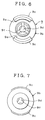
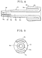
- the slider 9 has a sliding part 9c concentrically joined to the outer circumference of the rear end of the slider body 9b so as to extend forward, provided with a plurality of axial slits 9f and in sliding contact with the inner circumference of the tip 2 and held in place by a frictional resistance, and lead holding pieces 9i for applying a frictional resistance smaller than the frictional resistance applied to the sliding part 9c by the inner circumference of the tip 2 to the lead.
- the rear end of a lead guiding part 9e formed on the inner circumference of the rear end of the slider body 9b is joined to the rear end of the sliding part 9c, and has a plurality of connecting pieces 9k (Fig. 13), and a plurality of lead holding pieces 9i (Fig.
- each lead holding piece 9i tapered backward, separated from the connecting pieces 9k by a plurality of slits 9f extending from the rear toward the front and having rear ends not connected to the sliding part 9c.
- the connecting pieces 9k and the lead holding pieces 9i are separated from each other by the slits 9f and are arranged alternately on a circle.
- An arcuate lead holding protrusion 9g protrudes inward from the rear end of each lead holding piece 9i.
- the lead holding pieces 9i are formed so that the diameter of a circle circumscribed about the lead holding pieces 9i is equal to or greater than the diameter of a lead guiding opening 9j formed in the rear end of the lead guiding part 9e to prevent the lead being stopped when inserting the lead into the slider 9 from the rear end of the slider 9; that is, the outer surfaces of the lead holding pieces 9i are on the circumference of a circular cylinder corresponding to the inner circumference of the lead guiding opening 9j or on the circumference of a circular cylinder greater than the inner circumference of the lead guiding opening 9j. Since the lead can be easily guided into the lead guiding opening 9j without being caught and the rear ends of the lead holding pieces 9i are free, the lead holding pieces 9i can be easily bent radially outward and the lead can be automatically held.
- the operation of the slider 9 in the second embodiment having the lead guiding part 9e at its rear end is substantially similar to that of the slider 9 in the first embodiment having the lead guiding part 9e at its front end.
- the lead guide 10 may be a chip or a pipe.
- the slider body 9b and the lead guide 10 may be separate members or may be formed integrally.
- the number of the slits 9f formed in the lead guiding part 9e of the slider body 9b need not be limited to three or four as shown in the drawings, and the number of the sliding pieces of the sliding part 9c need not be limited to two.
Landscapes
- Mechanical Pencils And Projecting And Retracting Systems Therefor, And Multi-System Writing Instruments (AREA)
Applications Claiming Priority (2)
| Application Number | Priority Date | Filing Date | Title |
|---|---|---|---|
| JP287142/94 | 1994-10-28 | ||
| JP28714294A JP3466739B2 (ja) | 1994-10-28 | 1994-10-28 | シャープペンシルのスライダ |
Publications (2)
| Publication Number | Publication Date |
|---|---|
| EP0709233A1 true EP0709233A1 (fr) | 1996-05-01 |
| EP0709233B1 EP0709233B1 (fr) | 1998-12-23 |
Family
ID=17713619
Family Applications (1)
| Application Number | Title | Priority Date | Filing Date |
|---|---|---|---|
| EP95107442A Expired - Lifetime EP0709233B1 (fr) | 1994-10-28 | 1995-05-17 | Elément glisseur pour porte mine |
Country Status (7)
| Country | Link |
|---|---|
| US (1) | US5733057A (fr) |
| EP (1) | EP0709233B1 (fr) |
| JP (1) | JP3466739B2 (fr) |
| CN (1) | CN1051041C (fr) |
| BR (1) | BR9503037A (fr) |
| DE (1) | DE69506828T2 (fr) |
| ES (1) | ES2126178T3 (fr) |
Cited By (3)
| Publication number | Priority date | Publication date | Assignee | Title |
|---|---|---|---|---|
| EP1223050A1 (fr) * | 2001-01-10 | 2002-07-17 | Kotobuki & Co. Ltd. | Porte-mine |
| EP1184201A4 (fr) * | 2000-03-30 | 2009-09-23 | Pentel Kk | Porte-mine |
| EP1918124A3 (fr) * | 2006-10-31 | 2010-12-22 | Faber-Castell AG | Crayon mécanique |
Families Citing this family (5)
| Publication number | Priority date | Publication date | Assignee | Title |
|---|---|---|---|---|
| US6116799A (en) * | 1998-11-19 | 2000-09-12 | Kotobuki & Co., Ltd. | Installation structure of lead advancing mechanism in writing instrument |
| JP3388432B2 (ja) * | 1999-08-04 | 2003-03-24 | ミクロ株式会社 | シャ−プペンシル |
| JP4635380B2 (ja) * | 2001-05-31 | 2011-02-23 | ぺんてる株式会社 | シャープペンシル |
| CN103072403B (zh) * | 2013-01-06 | 2015-05-20 | 浙江科技学院 | 一种自动铅笔 |
| EP2815888B1 (fr) * | 2013-06-17 | 2019-08-28 | F.I.L.A. - Fabbrica Italiana Lapis ed Affini S.p.A | Outil de marquage |
Citations (6)
| Publication number | Priority date | Publication date | Assignee | Title |
|---|---|---|---|---|
| US4281939A (en) | 1979-06-04 | 1981-08-04 | Yoshihide Mitsuya | Mechanical pencil |
| EP0210280A1 (fr) * | 1985-01-26 | 1987-02-04 | Kabushiki Kaisha Kotobuki | Crayon toujours affute |
| EP0271249A1 (fr) | 1986-11-25 | 1988-06-15 | A.T. Cross Company | Porte-mine du type à mécanisme tournant |
| EP0311121A1 (fr) * | 1987-10-09 | 1989-04-12 | KOTOBUKI & CO., LTD. | Dispositif pour écrire |
| DE3910546C1 (en) * | 1989-04-01 | 1990-10-11 | J. S. Staedtler Gmbh & Co, 8500 Nuernberg, De | Fillable pencil with resiliently mounted lead clamping device |
| JPH0347907U (fr) | 1989-09-13 | 1991-05-07 |
Family Cites Families (1)
| Publication number | Priority date | Publication date | Assignee | Title |
|---|---|---|---|---|
| US4884910A (en) * | 1987-04-17 | 1989-12-05 | Kotobuki & Co., Ltd. | Mechanical pencil |
-
1994
- 1994-10-28 JP JP28714294A patent/JP3466739B2/ja not_active Expired - Fee Related
-
1995
- 1995-04-28 US US08/431,031 patent/US5733057A/en not_active Expired - Lifetime
- 1995-05-17 ES ES95107442T patent/ES2126178T3/es not_active Expired - Lifetime
- 1995-05-17 EP EP95107442A patent/EP0709233B1/fr not_active Expired - Lifetime
- 1995-05-17 DE DE69506828T patent/DE69506828T2/de not_active Expired - Lifetime
- 1995-06-19 CN CN95107378A patent/CN1051041C/zh not_active Expired - Fee Related
- 1995-06-30 BR BR9503037A patent/BR9503037A/pt not_active Application Discontinuation
Patent Citations (6)
| Publication number | Priority date | Publication date | Assignee | Title |
|---|---|---|---|---|
| US4281939A (en) | 1979-06-04 | 1981-08-04 | Yoshihide Mitsuya | Mechanical pencil |
| EP0210280A1 (fr) * | 1985-01-26 | 1987-02-04 | Kabushiki Kaisha Kotobuki | Crayon toujours affute |
| EP0271249A1 (fr) | 1986-11-25 | 1988-06-15 | A.T. Cross Company | Porte-mine du type à mécanisme tournant |
| EP0311121A1 (fr) * | 1987-10-09 | 1989-04-12 | KOTOBUKI & CO., LTD. | Dispositif pour écrire |
| DE3910546C1 (en) * | 1989-04-01 | 1990-10-11 | J. S. Staedtler Gmbh & Co, 8500 Nuernberg, De | Fillable pencil with resiliently mounted lead clamping device |
| JPH0347907U (fr) | 1989-09-13 | 1991-05-07 |
Cited By (4)
| Publication number | Priority date | Publication date | Assignee | Title |
|---|---|---|---|---|
| EP1184201A4 (fr) * | 2000-03-30 | 2009-09-23 | Pentel Kk | Porte-mine |
| EP1223050A1 (fr) * | 2001-01-10 | 2002-07-17 | Kotobuki & Co. Ltd. | Porte-mine |
| US6908246B2 (en) | 2001-01-10 | 2005-06-21 | Kotobuki & Co., Ltd. | Mechanical pencil |
| EP1918124A3 (fr) * | 2006-10-31 | 2010-12-22 | Faber-Castell AG | Crayon mécanique |
Also Published As
| Publication number | Publication date |
|---|---|
| CN1121466A (zh) | 1996-05-01 |
| EP0709233B1 (fr) | 1998-12-23 |
| US5733057A (en) | 1998-03-31 |
| BR9503037A (pt) | 1997-09-23 |
| DE69506828T2 (de) | 1999-08-12 |
| JP3466739B2 (ja) | 2003-11-17 |
| JPH08118883A (ja) | 1996-05-14 |
| DE69506828D1 (de) | 1999-02-04 |
| CN1051041C (zh) | 2000-04-05 |
| ES2126178T3 (es) | 1999-03-16 |
Similar Documents
| Publication | Publication Date | Title |
|---|---|---|
| US5988913A (en) | Double-chuck mechanical pencil | |
| EP0709233A1 (fr) | Elément glisseur pour porte mine | |
| US4171170A (en) | Automatic pencil | |
| US4386865A (en) | Automatic sharp pencil | |
| US4729684A (en) | Mechanical pencil | |
| US5947620A (en) | Double-chuck mechanical pencil | |
| US2528328A (en) | Clutch mechanism for mechanical pencils | |
| US5165813A (en) | Container with snap-in chuck and chuck ring | |
| US5882132A (en) | Side knock-type mechanical pencil | |
| US4521126A (en) | Mechanical pencil | |
| US4165941A (en) | Mechanical pencil | |
| EP0863023B1 (fr) | Porte-mine à deux pinces de serrage | |
| JP2560818Y2 (ja) | シャープペンシルのスライダ | |
| JPH0347907Y2 (fr) | ||
| US4571105A (en) | Lead engaging chuck mechanism for mechanical pencil | |
| KR970003358Y1 (ko) | 샤아프펜슬의 슬라이더 | |
| US4976560A (en) | Mechanical pencil with a plastic chuck | |
| JPS591839Y2 (ja) | シヤ−プペンシル | |
| KR880003396Y1 (ko) | 샤아프 펜슬 | |
| CN1038993C (zh) | 自动铅笔 | |
| JPH0245031Y2 (fr) | ||
| EP1018441A1 (fr) | Porte-mine automatique | |
| JP2025007329A (ja) | シャープペンシル | |
| KR880002379Y1 (ko) | 샤아프펜슬의 필심송출 슬라이더 | |
| JP2025007336A (ja) | シャープペンシル |
Legal Events
| Date | Code | Title | Description |
|---|---|---|---|
| PUAI | Public reference made under article 153(3) epc to a published international application that has entered the european phase |
Free format text: ORIGINAL CODE: 0009012 |
|
| AK | Designated contracting states |
Kind code of ref document: A1 Designated state(s): DE ES FR GB IT |
|
| 17P | Request for examination filed |
Effective date: 19960603 |
|
| 17Q | First examination report despatched |
Effective date: 19970409 |
|
| GRAG | Despatch of communication of intention to grant |
Free format text: ORIGINAL CODE: EPIDOS AGRA |
|
| GRAG | Despatch of communication of intention to grant |
Free format text: ORIGINAL CODE: EPIDOS AGRA |
|
| GRAH | Despatch of communication of intention to grant a patent |
Free format text: ORIGINAL CODE: EPIDOS IGRA |
|
| GRAH | Despatch of communication of intention to grant a patent |
Free format text: ORIGINAL CODE: EPIDOS IGRA |
|
| GRAA | (expected) grant |
Free format text: ORIGINAL CODE: 0009210 |
|
| AK | Designated contracting states |
Kind code of ref document: B1 Designated state(s): DE ES FR GB IT |
|
| REF | Corresponds to: |
Ref document number: 69506828 Country of ref document: DE Date of ref document: 19990204 |
|
| ITF | It: translation for a ep patent filed | ||
| REG | Reference to a national code |
Ref country code: ES Ref legal event code: FG2A Ref document number: 2126178 Country of ref document: ES Kind code of ref document: T3 |
|
| ET | Fr: translation filed | ||
| PGFP | Annual fee paid to national office [announced via postgrant information from national office to epo] |
Ref country code: GB Payment date: 19990401 Year of fee payment: 5 |
|
| PGFP | Annual fee paid to national office [announced via postgrant information from national office to epo] |
Ref country code: ES Payment date: 19990526 Year of fee payment: 5 |
|
| PLBE | No opposition filed within time limit |
Free format text: ORIGINAL CODE: 0009261 |
|
| STAA | Information on the status of an ep patent application or granted ep patent |
Free format text: STATUS: NO OPPOSITION FILED WITHIN TIME LIMIT |
|
| 26N | No opposition filed | ||
| PG25 | Lapsed in a contracting state [announced via postgrant information from national office to epo] |
Ref country code: GB Free format text: LAPSE BECAUSE OF NON-PAYMENT OF DUE FEES Effective date: 20000517 |
|
| PG25 | Lapsed in a contracting state [announced via postgrant information from national office to epo] |
Ref country code: ES Free format text: THE PATENT HAS BEEN ANNULLED BY A DECISION OF A NATIONAL AUTHORITY Effective date: 20000518 |
|
| GBPC | Gb: european patent ceased through non-payment of renewal fee |
Effective date: 20000517 |
|
| REG | Reference to a national code |
Ref country code: ES Ref legal event code: FD2A Effective date: 20020204 |
|
| PGFP | Annual fee paid to national office [announced via postgrant information from national office to epo] |
Ref country code: FR Payment date: 20030520 Year of fee payment: 9 |
|
| PG25 | Lapsed in a contracting state [announced via postgrant information from national office to epo] |
Ref country code: FR Free format text: LAPSE BECAUSE OF NON-PAYMENT OF DUE FEES Effective date: 20050131 |
|
| REG | Reference to a national code |
Ref country code: FR Ref legal event code: ST |
|
| PG25 | Lapsed in a contracting state [announced via postgrant information from national office to epo] |
Ref country code: IT Free format text: LAPSE BECAUSE OF NON-PAYMENT OF DUE FEES;WARNING: LAPSES OF ITALIAN PATENTS WITH EFFECTIVE DATE BEFORE 2007 MAY HAVE OCCURRED AT ANY TIME BEFORE 2007. THE CORRECT EFFECTIVE DATE MAY BE DIFFERENT FROM THE ONE RECORDED. Effective date: 20050517 |
|
| PGFP | Annual fee paid to national office [announced via postgrant information from national office to epo] |
Ref country code: DE Payment date: 20130603 Year of fee payment: 19 |
|
| REG | Reference to a national code |
Ref country code: DE Ref legal event code: R082 Ref document number: 69506828 Country of ref document: DE Representative=s name: EISENFUEHR SPEISER PATENTANWAELTE RECHTSANWAEL, DE Effective date: 20131010 Ref country code: DE Ref legal event code: R081 Ref document number: 69506828 Country of ref document: DE Owner name: KOTOBUKI & CO., LTD., KAWAGOE-SHI, JP Free format text: FORMER OWNER: KOTOBUKI & CO., LTD., KYOTO, JP Effective date: 20131010 Ref country code: DE Ref legal event code: R081 Ref document number: 69506828 Country of ref document: DE Owner name: KOTOBUKI & CO., LTD., JP Free format text: FORMER OWNER: KOTOBUKI & CO., LTD., KYOTO, JP Effective date: 20131010 |
|
| REG | Reference to a national code |
Ref country code: DE Ref legal event code: R119 Ref document number: 69506828 Country of ref document: DE |
|
| REG | Reference to a national code |
Ref country code: DE Ref legal event code: R119 Ref document number: 69506828 Country of ref document: DE Effective date: 20141202 |
|
| PG25 | Lapsed in a contracting state [announced via postgrant information from national office to epo] |
Ref country code: DE Free format text: LAPSE BECAUSE OF NON-PAYMENT OF DUE FEES Effective date: 20141202 |