EP0709316B1 - Übergabevorrichtung für auf einem umlaufenden endlosen Zuführband in Querreihen ankommenden Gegenständen - Google Patents
Übergabevorrichtung für auf einem umlaufenden endlosen Zuführband in Querreihen ankommenden Gegenständen Download PDFInfo
- Publication number
- EP0709316B1 EP0709316B1 EP95116462A EP95116462A EP0709316B1 EP 0709316 B1 EP0709316 B1 EP 0709316B1 EP 95116462 A EP95116462 A EP 95116462A EP 95116462 A EP95116462 A EP 95116462A EP 0709316 B1 EP0709316 B1 EP 0709316B1
- Authority
- EP
- European Patent Office
- Prior art keywords
- belt
- transfer belt
- transfer
- passing
- feed
- Prior art date
- Legal status (The legal status is an assumption and is not a legal conclusion. Google has not performed a legal analysis and makes no representation as to the accuracy of the status listed.)
- Expired - Lifetime
Links
- 238000012546 transfer Methods 0.000 claims description 146
- 238000012545 processing Methods 0.000 claims description 8
- 244000299461 Theobroma cacao Species 0.000 claims description 4
- 235000019219 chocolate Nutrition 0.000 claims description 4
- 235000009508 confectionery Nutrition 0.000 claims description 2
- 230000005540 biological transmission Effects 0.000 description 36
- 230000008878 coupling Effects 0.000 description 4
- 238000010168 coupling process Methods 0.000 description 4
- 238000005859 coupling reaction Methods 0.000 description 4
- 238000004140 cleaning Methods 0.000 description 3
- 238000013461 design Methods 0.000 description 3
- 238000004806 packaging method and process Methods 0.000 description 2
- 238000012856 packing Methods 0.000 description 2
- 238000013459 approach Methods 0.000 description 1
- 230000015556 catabolic process Effects 0.000 description 1
- 230000005484 gravity Effects 0.000 description 1
- 230000007257 malfunction Effects 0.000 description 1
- 238000000034 method Methods 0.000 description 1
- 239000000725 suspension Substances 0.000 description 1
Images
Classifications
-
- B—PERFORMING OPERATIONS; TRANSPORTING
- B65—CONVEYING; PACKING; STORING; HANDLING THIN OR FILAMENTARY MATERIAL
- B65G—TRANSPORT OR STORAGE DEVICES, e.g. CONVEYORS FOR LOADING OR TIPPING, SHOP CONVEYOR SYSTEMS OR PNEUMATIC TUBE CONVEYORS
- B65G47/00—Article or material-handling devices associated with conveyors; Methods employing such devices
- B65G47/52—Devices for transferring articles or materials between conveyors i.e. discharging or feeding devices
- B65G47/64—Switching conveyors
- B65G47/644—Switching conveyors by a pivoting displacement of the switching conveyor
- B65G47/645—Switching conveyors by a pivoting displacement of the switching conveyor about a horizontal axis
- B65G47/647—Switching conveyors by a pivoting displacement of the switching conveyor about a horizontal axis the axis being perpendicular to the conveying direction
Definitions
- the invention relates to a transfer device for on a objects arriving in transverse rows around the endless conveyor belt, especially confectionery parts, such as chocolate bars, Bars, chocolates or the like, with those in the preamble of the claim 1 specified characteristics.
- a transfer device will used in particular in front of a number of packaging machines which a stream of arriving in cross rows on a feed belt Items must be divided. In the top view, that takes Discharge belt an angle of 90 ° relative to the feed belt. It depends on the curb an uninterrupted Range of items for continuous operation of the Packing machine or another processing point enable.
- a transfer device of the type described at the outset is out US-A-3,605,982.
- the feed belt is one in the same Transfer belt working at the same height and conveying direction assigned.
- the transmission band is a cross axis extending to the conveying direction of the feed belt, this axis being in the longitudinal center of the transfer belt is arranged. The objects come up from the feed belt the transfer belt only by slipping down the inclined Level of the transmission belt.
- the relay tape is also pivotable about an axis extending transversely to the conveying direction, this axis being provided at the end of the relay belt is. It is a common swivel drive for the swiveling movements the transmission band and the transmission band provided that engages the relay belt. To do that too To pivot the transfer belt, this is at the beginning of the Passing belt mechanically coupled, that is, by a articulated rod or the like connected.
- the arrangement only a swivel drive for the two swivel movements of the Transfer tape on the one hand and the transfer tape on the other advantageously simplifies the structural complexity of the transfer device.
- the transmission tape becomes disadvantageous when removing the items from the feed belt in a substantial inclined position so that there is a risk that the objects arriving in transverse rows on the transfer belt can slip.
- This is done via a stop bar Preventing objects from falling off the transfer belt.
- the considerable skew of the transfer belt at the time of recording for objects that are brought up on the feed belt is required to keep the items on at all get the transfer belt because a separate drive for the required movement is not provided and only so far the force of gravity on the objects is used.
- the discharge belt connects to the transfer belt at the head and the direction of conveyance of the transfer belt coincides with that of the discharge belt so that the objects only one after the other can get onto the discharge belt.
- the discharge belt is driven by the packing machine, i.e. it can in Connection to the transfer of one corresponding to a transverse row Number of objects from the transfer belt to the discharge belt continue to run, so that then necessarily on the discharge belt a gap arises.
- a variable-length transmission belt is provided, which is pivotable about an axis transverse to the conveying direction in two positions is pivotable, being in one position has a connection to the lowered nose of the feed belt and so Can hold objects while in the other position Has connection to the discharge belt and thus a transverse row of Items are delivered to the discharge conveyor at once can. If the nose of the feed belt is not lowered, has they connect to a relay band, which is in horizontal Conveyor level connects to the feed belt. Get advantageous so that the objects from the feed belt to the Passing tape.
- Another transfer device is known from AT-A-268 144.
- the feed belt is split, in particular around it swivel upward to a sloping position can.
- the divided end of the feed belt can also in a downward sloping position can be pivoted when the Level of the discharge belt below the level of the feed belt and of the relay band is arranged.
- the intended one Transfer belt works as a circulating belt in the conveying direction. It is itself divided into parts, so be that Start of a horizontal position facing the end of the feed belt can be swiveled into an inclined position and vice versa.
- the transfer belt that follows is also on the funding level split trained, and its the turnable like a switch
- the end of the feed belt facing part can also be made from a Horizontal position around a transverse to the conveying direction Axis can be swiveled into an inclined position. In this inclined position no objects can be picked up, however the passage cross-section thus enlarged proves, in particular advantageous for relatively tall objects.
- the transmission band used is not driven to move back and forth, but as endless revolving band. A tape guide is therefore required.
- the invention has for its object a transmission device to provide the type described above, with a rotary drive for the transfer belt and the transfer belt gets along and still excessive inclinations of the transfer belt can be avoided so that the objects in Transverse rows gently picked up by the transfer belt and delivered across the rows to the discharge belt without gaps can be.
- this is the case with the transfer device at the beginning described type achieved in that the transfer belt for simultaneously pushing on a transverse row of objects back and forth from the transfer belt to the discharge belt hereby driven slide with tape, and that the transfer belt around which is transverse to the conveying direction extending axis of the relay band or beyond this axis arranged in infinity is pivotable.
- the transfer belt and at least the swiveling one Part of the relay belt mechanically coupled, in particular are arranged on a common frame.
- Another Possibility is that the transmission band for his Movement in an approximately vertical direction via translatory, in particular vertically acting guide elements is guided.
- the invention picks up a type of transfer device those when dividing a stream of objects in rows the end of the feed belt is not pivotable.
- the discharge belt is not pivotable anyway, but only in an outside of the conveyor level of the feed belt and the Passing tape lying level are, as it were only the beginnings of the pass-on volume downstream of the transfer point on the one hand and the transmission band on the other designed to pivot the objects in transverse rows of to slide the transfer belt onto the discharge belt and so on to form adjacent rows of the discharge belt.
- the transmission tape has to be pushed on at the same time a transverse row of objects from the transfer belt the leader belt a reciprocally driven slider with belt that is driven back and forth in the conveying direction and controlled.
- the discharge belt is next to the transfer belt arranged and is driven transversely to the conveying direction.
- pivoting the transfer belt together and the transfer belt is only a single swivel drive utilized.
- a counter-rotating transfer case is not necessary.
- the transmission band is above the Passing tape is arranged, there is a good clarity the elements of the transfer device, so that at Malfunctions can be intervened easily and quickly.
- the cleaning options are improved without it this requires special design features, such as. B. swivel Beginnings of the band or the like ..
- the different Items handed over to processing sites arrive only once in an inclined position or are pivoted only once. At a immediate transfer from the end of the feed belt to the Any slant of the objects will be the beginning of the pass-through tape avoided.
- the relay belt can also be designed as a split belt be. The same applies to the feed belt.
- the division of this Tapes require a certain amount of effort in terms of design and in particular also the arrangement of separate drives for the parts of the Tapes when the parts of the tapes are controlled differently gaps between the rows of rows close.
- the transfer belt and at least the pivotable part of the Passing tape can be mechanically coupled, in particular be arranged on a common frame.
- the common one The swivel drive then acts on this frame and provides in one position and one connection of the transmission band to the discharge belt as well as a connection of the transfer belt to the feed belt. In the other position only closes the transfer belt to the feed belt. There is no need separate storage for the transfer belt.
- the pivot axis of the pass-on volume is used sensibly here.
- the transmission band anyway has only a relatively small expansion in Direction of conveyance. Through the back and forth movement of the Transfer belt - in contrast to an endlessly rotating one Band - it can be constructed very easily even constructively be avoided, a special tape guide is avoided.
- the transfer belt and at least the pivotable part of the on the other hand, the transfer belt can also be moved mechanically be coupled, wherein for the movement of the transfer belt translational in approximately vertical direction, in particular vertically acting, guide elements are provided.
- This provides the advantage that the objects on the transfer belt take a horizontal position at any time and an inclined position is avoided. This is particularly related with the back and forth movement of the transfer belt to see yourself, that is when shooting objects on the one hand and on the other hand when it comes to delivery.
- mechanical movable coupling can be a coupling rod with corresponding Joints can be provided.
- a coordination of the swivel movement of the relay belt and the vertical movement of the transmission belt each other must be provided.
- the common drive for the movements becomes particularly simple the transmission band on the one hand and the relay band on the other hand, if a crank drive as a common drive is provided.
- a crank mechanism also has one sinusoidal movement so that the approach to the connection points is advantageously slowed down comparatively.
- the feed belt can be divided, in which case two separately controllable drives for the two in the conveying direction adjoining parts of the feed belt are provided are. With appropriate control, this enables Closing gaps between the successive transverse rows. Overflowed at the last distribution point Objects are conveyed back into the processing process and thus to the last processing point.
- the transmission band can be above or below the transmission band be arranged.
- the two transfer points between the feed belt and the transfer belt on the one hand and the transfer belt and the discharge belt, on the other hand, are thus vertical provided one above the other, so that overall one advantageous short overall length of the entire transfer device results.
- the transfer belt can have a movable belt, which with one acting in the conveying direction of the feed belt back and forth drive is provided.
- the direction of funding of the transfer belt and the conveying direction of the feed belt agree or are directed in opposite directions. The Objects are thus removed from the belt of the transfer belt promoted gently.
- the transfer belt can be shorter than that in the conveying direction Passing tape be formed. Only if the transfer belt should also perform a storage function and several Cross rows are to be included, its extent in Direction of conveyance increased accordingly. In all of these cases however, there is a good overview and an easier one Possibility of cleaning.
- a guided pusher can be attached to the belt of the transfer belt be arranged, which can be connected to a drive, the band being connected to the slider. This endless However, the band does not run, but is indirectly via the Slider driven back and forth. This eliminates one elaborate tape guide, and the risk of running a endless belt is avoided.
- the vertical offset of the beginning of the transfer belt and the Passing tape is advantageous with the vertical distance between the feed belt and the discharge belt so that in one common position the feed belt to the transfer belt Has connection and at the same time connection between the transmission band and the discharge belt. Objects can thus passed on simultaneously and on a different level other objects are removed.
- the mechanically firmly coupled Framework of the relaying tape and the transfer tape in be arranged at an angle to each other. This angle corresponds expediently at half the angle of the inclined position horizontal orientation.
- the possible inclination of the Objects are reduced in size and the overall length is short. It is not necessary to make the pass-through tape particularly long train or the pivot axis of the transfer belt in relatively large distance from the beginning of the pass-through volume to arrange.
- FIG. 1 the end of a feed belt 1 is shown schematically, whose endlessly circulating band 2 in the area of a Transfer point 3 is looped around a deflection roller 4.
- the deflecting roller 4 can also have a knife-like band edge be provided.
- Objects 5, lying side by side in transverse rows, are funded in funding direction 6.
- the feed belt 1 has a continuously acting drive, which here is not shown in detail.
- the guide roller 4 and thus that End of the feed belt 1 is arranged stationary, so that the Cross rows of objects 5 always in the same place Transfer point 3 can be delivered.
- a transfer belt 7 is provided at the transfer point 3, which extends substantially perpendicular to the feed belt 1.
- the discharge belt 7 also has an endless belt 8, which is provided with its own drive. Controlled via corresponding discharge and control means can be carried out by the discharge belt 7 each take a transverse row of objects 5, so that now on the discharge belt 7, the objects 5 in one Conveyed one after the other and a processing station, for example, a packaging machine.
- the discharge belt 7 with its conveyor level arranged above the conveying plane of the feed belt 1.
- a transfer belt 9 is provided which has a frame 10 which is T-shaped here having.
- the frame 10 of the transmission belt 9 are guides 11 assigned, for example slide rails, so that the transfer belt 9 is guided vertically movable.
- the transmission band 9 has a slide 12, which has its own, not here back and forth drive shown.
- the slider 12 is connected to a band 13, which is driven indirectly via the slide 12 and thus each in front of the slide 12 a receiving surface for a transverse row of Provides objects 5 on the frame 10.
- a transmission belt 14 is located below the transmission belt 9 provided which has an endless belt 15 which with a own drive is provided.
- Volume 15 of the redistribution volume 14 is about a fixed axis 16 or a deflection roller 17 pivotable, with a pivoting movement of the transfer point 3 facing the beginning 18 of the pass-through volume 14 moved an arc around the axis 16.
- On the pass-through tape 14 are transverse rows of items 5 by the transfer belt 9 were not taken over, promoted according to arrow 19 and fed to a further transfer device on which turn a branch of transverse rows of objects 5 take place can, as already for the illustrated discharge belt 7th was shown and described.
- the crank drive 21 can have with push rod 22.
- the push rod 22 attacks on the frame 10 of the transmission belt 9. She can also on the only partially indicated frame 23 of the relay tape Attack 14.
- the two frames 10 and 23 are mechanical coupled, the coupling point being articulated here, the differences in movement of the vertical movement of the transfer belt 9 and the pivoting movement of the transfer belt 14 To take into account.
- the feed belt 1 and the transfer belt 14 can be separate separate parts can be formed and arranged, as is shown in this 1 has been described. Both the feed belt 1 as well the transfer belt 14 can also be divided into several Bands exist, then the pivoting mobility of the Passing tape 14 only on its first, the transfer point 3 assigned part limited.
- Through the series connection of the feed belt 1 and the transfer belt 14 in Conveying direction 6 is the overall length of a transfer device certainly. But it is also possible for the transfer device to do so to modify that the feed belt 1 and the transfer belt 14 a and represent the same band, so that, as it were, immediately Another transfer point 3 is created behind the deflection roller 17 is. It is understood that at least two series connected Transfer device are provided when a Flow of objects 5 arriving in transverse rows to at least two processing stations are to be divided.
- FIG. 1 shows the lowered position of the transfer belt 9 and the transfer belt 14, so that the transfer belt 9 has a connection to the end of the feed belt 1.
- the transverse row of objects 5 located directly at the end of the feed belt 1 is to be picked up by the transfer belt 9.
- the slide 12 is in a position facing the transfer point 3 with the aid of its drive, so that it can still perform an alignment function while the transverse row is being taken over.
- the slider 12 is moved back according to arrow 24 in the conveying direction 6 relative to the frame 10 of the transfer belt 9, while the belt 2 of the feed belt 1 is continuously driven.
- this transverse row arrives at the transfer belt 9, the slide 12 having reached its other end position in the fully accommodated position (FIG. 2).
- the belt 15 of the transfer belt 14 has continued to run according to arrow 19, so that a row of objects 5 that was previously on the transfer belt 14 has been transported accordingly.
- the same also applies to transverse rows of objects 5 on the feed belt 1.
- FIGS Figures 5 and 6 Another embodiment of the transfer device is shown in FIGS Figures 5 and 6 shown, the discharge belt 7 is not above the conveyor level consisting of feed belt 1 and transfer belt 14, but is located below this level.
- the feed belt 1 is divided to fill gaps between the transverse rows of the To be able to close items 5.
- a partial feed belt 30 which also has a circumferential belt 2.
- the partial feed belt 30 is equipped with a separately controllable drive, which is here is not shown.
- the deflecting roller 4 Belt 2 of the partial feed belt 30 arranged stationary. Things 5 are in transverse rows in the conveying direction 6 to the transfer point 3 introduced.
- the discharge belt 7 also has a circumferential belt 8 here its own drive.
- the transmission band 9 has one Frame 10, which is fixed to the frame 23 of the relay belt 14 connected is.
- a common framework has been created, the frame 10 with its main plane opposite the Main plane of the frame 23 is arranged inclined at an angle is that of half the pivoting angle of the relay belt 14 corresponds to its axis 16.
- the transmission band also has here 9 a slide 12 and a band 13 attached to it.
- the transfer belt 14 also has a circulating belt 15 here.
- the axis 16 about which the transfer belt 14 can be pivoted becomes realized by a deflecting roller 17.
- the beginning 18 of the redistribution volume 14 is in the takeover position shown in FIG raised so that the transverse row of objects 5 that are on the circulating belt 15 of the relay belt 14, according to Arrow 19 is promoted.
- the transfer belt 9 is for Recording the next transverse row from objects 5 ready dispensed via the partial feed belt 30 and the deflection roller 4 become.
- the swivel drive 20 also has a crank drive here 21 with a push rod 22 which is in a pivot bearing 31 on the common frame of the frame 10 of the transmission tape and attacks the frame 23 on the relay belt.
Landscapes
- Engineering & Computer Science (AREA)
- Mechanical Engineering (AREA)
- Structure Of Belt Conveyors (AREA)
- Branching, Merging, And Special Transfer Between Conveyors (AREA)
Description
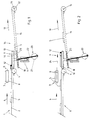
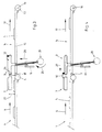
- Figur 1
- eine schematisierte Seitenansicht einer ersten Ausführungsform der Übergabevorrichtung, vor der Übernahme einer Querreihe von Gegenständen auf das Übertragungsband,
- Figur 2
- die Relativlage der Teile nach der vollständigen Aufnahme einer Querreihe auf dem Übertragungsband,
- Figur 3
- die Relativlage der Teile nach dem Anheben des Übertragungsbandes,
- Figur 4
- die Relativlage der Teile nach dem Abschieben einer Querreihe von dem Übertragungsband auf das Abführband,
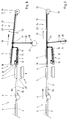
- Figur 5
- eine schematisierte Seitenansicht einer zweiten Ausführungsform der Übergabevorrichtung, vor der Übernahme einer Querreihe von Gegenständen auf das Übertragungsband und
- Figur 6
- die Relativlage der Teile nach dem Absenken des Übertragungsbandes.
Figur 1 zeigt die abgesenkte Stellung des Übertragungsbandes 9 und des Weitergabebandes 14, so daß das Übertragungsband 9 Anschluß an das Ende des Zuführbandes 1 besitzt. Die unmittelbar am Ende des Zuführbandes 1 befindliche Querreihe von Gegenständen 5 soll von dem Übertragungsband 9 aufgenommen werden. Zu diesem Zweck befindet sich der Schieber 12 mit Hilfe seines Antriebes in einer der Übergabestelle 3 zugekehrten Stellung, so daß er während der Übernahme der Querreihe noch eine Ausrichtfunktion ausführen kann. Wie ein Vergleich der Figuren 1 und 2 erkennen läßt, wird der Schieber 12 gemäß Pfeil 24 in Förderrichtung 6 relativ zum Rahmen 10 des Übertragungsbandes 9 zurückbewegt, während das Band 2 des Zuführbandes 1 kontinuierlich weiter angetrieben wird. Demzufolge gelangt diese Querreihe auf das Übertragungsband 9, wobei in der vollkommenen aufgenommenen Stellung (Figur 2) der Schieber 12 seine andere Endposition erreicht hat. Während dieser Förderbewegung ist auch das Band 15 des Weitergabebandes 14 gemäß Pfeil 19 weitergelaufen, so daß eine zuvor bereits auf dem Weitergabeband 14 befindliche Reihe von Gegenständen 5 entsprechend weitertransportiert worden ist. Gleiches gilt auch für Querreihen von Gegenständen 5 auf dem Zuführband 1.
- 1
- - Zuführband
- 2
- - Band
- 3
- - Übergabestelle
- 4
- - Umlenkwalze
- 5
- - Gegenstand
- 6
- - Förderrichtung
- 7
- - Abführband
- 8
- - Band
- 9
- - Übertragungsband
- 10
- - Rahmen
- 11
- - Führung
- 12
- - Schieber
- 13
- - Band
- 14
- - Weitergabeband
- 15
- - Band
- 16
- - Achse
- 17
- - Umlenkwalze
- 18
- - Anfang
- 19
- - Pfeil
- 20
- - Schwenkantrieb
- 21
- - Kurbeltrieb
- 22
- - Schubstange
- 23
- - Rahmen
- 24
- - Pfeil
- 25
- - Pfeil
- 26
- - Versatz
- 27
- - Abstand
- 28
- - Pfeil
- 29
- - Pfeil
- 30
- - Teilzuführband
- 31
- - Schwenklager
- 32
- - Doppelpfeil
Claims (11)
- Übergabevorrichtung für auf einem umlaufenden endlosen Zuführband (1) in Querreihen ankommende Gegenstände (5), insbesondere Süßwarenteile, wie Schokoladetafeln, Riegel, Pralinen od. dgl., an mindestens zwei Verarbeitungsstellen, wobei dem Zuführband (1) ein insbesondere in gleicher Höhe und gleicher Förderrichtung (6) arbeitendes Weitergabeband (14) einerseits und ein außerhalb der Ebene des Zuführbandes (1) angeordnetes Abführband (7) andererseits nachgeschaltet sind und zwischen Zuführband (1) und Abführband (7) ein Übertragungsband (9) vorgesehen ist, das mit dem Weitergabeband (14) gekoppelt ist und über einen gemeinsamen Schwenkantrieb (20) für die Bewegungen des Übertragungsbandes (9) und des gekoppelten Weitergabebandes (14) zwischen einem Anschluß des Weitergabebandes (14) an das Zuführband (1) und einem Anschluß des Übertragungsbandes (9) an das Zuführband (1) hin- und herbeweglich angetrieben ist, wobei das dem Weitergabeband (14) bzw. dem Übertragungsband (9) zugekehrte Ende des Zuführbandes (1) ortsfest angeordnet ist, zumindest der dem Ende des Zuführbandes (1) zugekehrte Anfang (18) des Weitergabebandes (14) um eine sich quer zur Förderrichtung (6) erstreckende Achse (16) schwenkbar ist und das Übertragungsband (9) um eine sich quer zur Förderrichtung (6) erstreckende Achse schwenkbar ist, dadurch gekennzeichnet, daß das Übertragungsband (9) zum gleichzeitigen Aufschieben einer Querreihe von Gegenständen (5) von dem Übertragungsband (9) auf das Abführband (7) einen hin- und hergehend angetriebenen Schieber (12) mit Band (13) aufweist, und daß das Übertragungsband (9) um die sich quer zur Förderrichtung (6) erstreckende Achse (16) des Weitergabebandes (14) oder um eine jenseits dieser Achse (16) im Unendlichen angeordnete Achse schwenkbar ist.
- Übergabevorrichtung nach Anspruch 1, dadurch gekennzeichnet, daß das Übertragungsband (9) und zumindest der schwenkbare Teil des Weitergabebandes (14) mechanisch fest gekoppelt, insbesondere auf einem gemeinsamen Rahmen (10, 23) angeordnet, sind.
- Übergabevorrichtung nach Anspruch 1, dadurch gekennzeichnet, daß das Übertragungsband (9) für seine Bewegung in etwa vertikaler Richtung über translatorische, insbesondere vertikal wirkende, Führungselemente (11) geführt ist.
- Übergabevorrichtung nach Anspruch 2 oder 3, dadurch gekennzeichnet, daß als gemeinsamer Antrieb (20) für die Bewegungen des Übertragungsbandes (9) und des Weitergabebandes (14) ein Kurbeltrieb (21) vorgesehen ist.
- Übergabevorrichtung nach Anspruch 2 oder 3, dadurch gekennzeichnet, daß das Zuführband (1) geteilt ausgebildet ist, und daß zwei getrennt steuerbare Antriebe für die beiden in Förderrichtung (6) aneinander anschließenden Teile des Zuführbandes (1) vorgesehen ist.
- Übergabevorrichtung nach Anspruch 2 oder 3, dadurch gekennzeichnet, daß das Übertragungsband (9) oberhalb oder unterhalb des Weitergabebandes (14) angeordnet ist.
- Übergabevorrichtung nach Anspruch 2 oder 3, dadurch gekennzeichnet, daß das Übertragungsband (9) ein Band (13) aufweist, welches mit einem in Förderrichtung (6) des Zuführbandes (1) wirkenden hin- und hergehenden Antrieb gemäß den Pfeilen (24, 29) versehen ist.
- Übergabevorrichtung nach Anspruch 6, dadurch gekennzeichnet, daß das Übertragungsband (9) in Förderrichtung kürzer als das Weitergabeband (14) ausgebildet ist.
- Übergabevorrichtung nach Anspruch 6, dadurch gekennzeichnet, daß an dem Band (13) des Übertragungsbandes (9) ein geführter Schieber (12) angeordnet ist.
- Übergabevorrichtung nach Anspruch 2 oder 3, dadurch gekennzeichnet, daß der vertikale Versatz (26) der Anfänge des Übertragungsbandes (9) und des Weitergabebandes (14) mit dem vertikalen Abstand (27) zwischen Zuführband (1) und Abführband (7) übereinstimmt.
- Übergabevorrichtung nach Anspruch 2, dadurch gekennzeichnet, daß die mechanisch fest miteinander gekuppelten Rahmen (10, 23) des Weitergabebandes (14) und des Übertragungsbandes (9) in einem Winkel zueinander angeordnet sind.
Applications Claiming Priority (2)
| Application Number | Priority Date | Filing Date | Title |
|---|---|---|---|
| DE4438207A DE4438207C2 (de) | 1994-10-26 | 1994-10-26 | Übergabevorrichtung für auf einem umlaufenden endlosen Zuführband in Querreihen ankommenden Gegenstände |
| DE4438207 | 1994-10-26 |
Publications (2)
| Publication Number | Publication Date |
|---|---|
| EP0709316A1 EP0709316A1 (de) | 1996-05-01 |
| EP0709316B1 true EP0709316B1 (de) | 1999-04-21 |
Family
ID=6531719
Family Applications (1)
| Application Number | Title | Priority Date | Filing Date |
|---|---|---|---|
| EP95116462A Expired - Lifetime EP0709316B1 (de) | 1994-10-26 | 1995-10-19 | Übergabevorrichtung für auf einem umlaufenden endlosen Zuführband in Querreihen ankommenden Gegenständen |
Country Status (3)
| Country | Link |
|---|---|
| US (1) | US5715930A (de) |
| EP (1) | EP0709316B1 (de) |
| DE (1) | DE4438207C2 (de) |
Families Citing this family (24)
| Publication number | Priority date | Publication date | Assignee | Title |
|---|---|---|---|---|
| NL1003975C2 (nl) * | 1996-09-06 | 1998-03-09 | Vanderlande Ind Nederland | Inrichting voor het transporteren van voorwerpen. |
| DE19721397C2 (de) * | 1997-05-22 | 1999-04-08 | Wilhelm Hogenkamp Verpackungst | Übergabevorrichtung für auf einem umlaufenden endlosen Zuführband in Querreihen ankommende Gegenstände |
| US5984078A (en) * | 1997-08-04 | 1999-11-16 | United Parcel Service Of America, Inc. | Automated shuttle sorter for conveyors |
| DE19914816C2 (de) * | 1998-03-31 | 2000-12-21 | Siemens Ag | Vertikal schwenkbares Fördermodul |
| WO2000059815A1 (de) | 1999-03-31 | 2000-10-12 | Siemens Aktiengesellschaft | Vertikal schwenkbares fördermodul |
| WO2001066446A1 (de) | 2000-03-09 | 2001-09-13 | Siemens Aktiengesellschaft | Fördereinrichtung zum transport und ausschleusen von fördergut |
| DE10018770C1 (de) * | 2000-04-15 | 2001-10-31 | Koenig & Bauer Ag | Vorrichtung zum Ausschleusen von Signaturen aus einem Falzapparat |
| US6467606B1 (en) * | 2000-08-14 | 2002-10-22 | Langen Packaging, Inc. | Conveyor system with diverter |
| WO2002070376A2 (en) | 2001-02-02 | 2002-09-12 | Siemens Aktiengesellschaft | Vertical diverter assembly |
| JP4811974B2 (ja) * | 2001-05-11 | 2011-11-09 | 株式会社イシダ | 物品の振分装置 |
| DE10255344A1 (de) * | 2002-11-27 | 2005-06-30 | Siemens Ag | Fördersystem für Güter, insbesondere Behälter für Gepäckstücke, und Steuerverfahren für das Fördersystem |
| US6866135B2 (en) * | 2003-02-28 | 2005-03-15 | Quad/Tech, Inc. | Conveyor waste gate |
| US6883659B2 (en) * | 2003-06-30 | 2005-04-26 | Ivan Muchalov | Conveyor transfer assembly |
| US6974020B1 (en) * | 2004-05-17 | 2005-12-13 | Peppel George W | High speed baggage diverter |
| FR2917374B1 (fr) * | 2007-06-15 | 2009-12-18 | Airbus France | Dispositif de convoyage destine notamment a des bagages dans une soute d'un aeronef |
| ITBO20080525A1 (it) * | 2008-08-27 | 2010-02-28 | Dp Srl | Dispositivo di movimentazione, particolarmente per macchine di confezionamento |
| DE102009008155A1 (de) * | 2009-02-09 | 2010-08-19 | SSI Schäfer PEEM GmbH | Entladestation zum automatisierten Trennen eines Gebindes von einem Ladehilfsmittel |
| MX364365B (es) | 2012-02-03 | 2019-04-24 | Span Tech Llc | Sistemas de ordenamiento y metodos relacionados. |
| DE102014202087A1 (de) * | 2014-02-05 | 2015-08-06 | Loesch Verpackungstechnik Gmbh | Vorrichtung und Verfahren zum Aufteilen eines Stroms stückiger Produkte |
| US9277833B1 (en) | 2014-02-07 | 2016-03-08 | Pan Oston Holding Company | Multi-destination checkout system and related methods |
| CN108995875B (zh) * | 2017-10-16 | 2023-06-09 | 青岛海科佳智能科技股份有限公司 | 送面翻转装置 |
| US10937683B1 (en) * | 2019-09-30 | 2021-03-02 | Applied Materials, Inc. | Conveyor inspection system, substrate rotator, and test system having the same |
| DE102021113902A1 (de) | 2021-05-28 | 2022-12-01 | Syntegon Packaging Systems Ag | Fördervorrichtung zu einem Fördern von Produkten, insbesondere von verpackten und/oder unverpackten Lebensmitteln, sowie Produktionsanlage und Verfahren mit einer derartigen Fördervorrichtung zu einem Fördern von Produkten |
| CN116762837B (zh) * | 2023-08-24 | 2023-10-27 | 常州元盼食品有限公司 | 一种面包生产线用多功能传输装置和判断方法 |
Family Cites Families (10)
| Publication number | Priority date | Publication date | Assignee | Title |
|---|---|---|---|---|
| DE268144C (de) * | ||||
| BE678711A (de) * | 1965-04-07 | 1966-09-01 | ||
| DE1917062C3 (de) * | 1969-04-02 | 1978-10-19 | Maschinenfabrik Loesch Gmbh, 8550 Forchheim | Vorrichtung zum selbsttätigen Verteilen von Gegenständen |
| DE2133389A1 (de) * | 1971-07-05 | 1973-01-18 | Michael Christian Ludowici | Verfahren und vorrichtung zum bilden einer einzelreihe aus zwei reihen keramischer erzeugnisse |
| DE2831323C2 (de) * | 1978-07-17 | 1982-06-16 | Otto Hänsel GmbH, 3000 Hannover | Übergabevorrichtung für auf einem umlaufenden endlosen Zuführband in Querreihen ankommende Gegenstände, insbesondere Süßwarenteile wie Schokoladetafeln- oder riegel, Pralinen usw., an mindestens zwei Verarbeitungsstellen |
| CH655286A5 (de) * | 1982-05-03 | 1986-04-15 | Sig Schweiz Industrieges | Vorrichtung zum wahlweisen umlenken von gegenstaenden auf eines von zwei foerderbaendern, verfahren zu ihrem betrieb und verwendung. |
| CH659232A5 (de) * | 1983-01-14 | 1987-01-15 | Grapha Holding Ag | Vorrichtung zum wenden von aus druckbogen bestehenden teilschuppen. |
| JPS6422758A (en) * | 1987-07-16 | 1989-01-25 | Meinan Machinery Works | Distributed transport device for board |
| IT1254217B (it) * | 1992-02-25 | 1995-09-14 | Dispositivo di trasferimento selettivo di file di prodotti fra coppie di nastri trasportatori | |
| US5499719A (en) * | 1995-02-13 | 1996-03-19 | Formax, Inc. | Takeaway/correction conveyor system for food product machine |
-
1994
- 1994-10-26 DE DE4438207A patent/DE4438207C2/de not_active Expired - Fee Related
-
1995
- 1995-10-19 EP EP95116462A patent/EP0709316B1/de not_active Expired - Lifetime
- 1995-10-26 US US08/548,489 patent/US5715930A/en not_active Expired - Fee Related
Also Published As
| Publication number | Publication date |
|---|---|
| EP0709316A1 (de) | 1996-05-01 |
| DE4438207A1 (de) | 1996-05-02 |
| DE4438207C2 (de) | 2002-07-18 |
| US5715930A (en) | 1998-02-10 |
Similar Documents
| Publication | Publication Date | Title |
|---|---|---|
| EP0709316B1 (de) | Übergabevorrichtung für auf einem umlaufenden endlosen Zuführband in Querreihen ankommenden Gegenständen | |
| EP2500296B1 (de) | Vorrichtung und Verfahren zum Gruppieren von Stückgut | |
| DE19853685B4 (de) | Vorrichtung zum Umsetzen eines Gegenstandes | |
| DE2125991A1 (de) | Verfahren und Vorrichtung zum Transport gestapelter flacher Gegenstände in Aufeinanderfolge zu einem Auffangen | |
| EP0622315A2 (de) | Vorrichtung zum Transport von Produkten | |
| DE2915180A1 (de) | Laengenveraenderlicher bandfoerderer | |
| EP3366614A2 (de) | Zufuhrketten-einheit | |
| DE2754918C2 (de) | Einrichtung zum Herstellen gleicher Abstände zwischen Stückgütern auf einem Transportband | |
| DE3422150A1 (de) | Foerdereinrichtung | |
| DE2820477A1 (de) | Zigarettenverpackungsmaschine | |
| DE19500546B4 (de) | Modul zum Führen eines entlang einer Transferstrecke bewegbaren Werkstückträgers | |
| DE2435200C2 (de) | Fördervorrichtung für eine Ziegelherstellmaschine | |
| DE19845836B4 (de) | Vorrichtung zum Verteilen von Stückgut auf mehrere weiterführende Förderbahnen | |
| EP1351783A1 (de) | Vorrichtung zum querteilen von metallbändern | |
| AT394010B (de) | Anlage zum fuellen und verschliessen von oben offenen saecken | |
| DE19603125C2 (de) | Übergabevorrichtung für in Querreihen oder Gruppen ankommende Gegenstände auf ein Austrageband | |
| DE3815557A1 (de) | Verbundmaschine zum automatischen verpacken von packgut in faltschachteln | |
| DE3208801A1 (de) | Weiche fuer riemenfoerderer fuer waffelbloecke u.dgl. | |
| EP0657259A1 (de) | Tonstrang-Schneidevorrichtung | |
| DE3715923A1 (de) | Anordnung zum umformen eines angefoerderten mehrspurigen flaschenstromes in einen abzufoerdernden einspurigen flaschenstrom | |
| DE3537952A1 (de) | Anlage zum fuellen und verschliessen von oben offenen saecken | |
| DE4111632C2 (de) | Montagelinie | |
| EP1771360B1 (de) | Fördereinrichtung | |
| EP0159622B1 (de) | Siebdruckmaschine mit einem festen Drucktisch | |
| DE3429285A1 (de) | Vorrichtung zum umhuellen von bloecken |
Legal Events
| Date | Code | Title | Description |
|---|---|---|---|
| PUAI | Public reference made under article 153(3) epc to a published international application that has entered the european phase |
Free format text: ORIGINAL CODE: 0009012 |
|
| AK | Designated contracting states |
Kind code of ref document: A1 Designated state(s): CH GB IT LI NL |
|
| 17P | Request for examination filed |
Effective date: 19960424 |
|
| 17Q | First examination report despatched |
Effective date: 19970221 |
|
| GRAG | Despatch of communication of intention to grant |
Free format text: ORIGINAL CODE: EPIDOS AGRA |
|
| GRAG | Despatch of communication of intention to grant |
Free format text: ORIGINAL CODE: EPIDOS AGRA |
|
| GRAH | Despatch of communication of intention to grant a patent |
Free format text: ORIGINAL CODE: EPIDOS IGRA |
|
| GRAH | Despatch of communication of intention to grant a patent |
Free format text: ORIGINAL CODE: EPIDOS IGRA |
|
| GRAH | Despatch of communication of intention to grant a patent |
Free format text: ORIGINAL CODE: EPIDOS IGRA |
|
| GRAH | Despatch of communication of intention to grant a patent |
Free format text: ORIGINAL CODE: EPIDOS IGRA |
|
| GRAA | (expected) grant |
Free format text: ORIGINAL CODE: 0009210 |
|
| AK | Designated contracting states |
Kind code of ref document: B1 Designated state(s): CH GB IT LI NL |
|
| REG | Reference to a national code |
Ref country code: CH Ref legal event code: NV Representative=s name: DR. CONRAD A. RIEDERER PATENTANWALT Ref country code: CH Ref legal event code: EP |
|
| GBT | Gb: translation of ep patent filed (gb section 77(6)(a)/1977) |
Effective date: 19990421 |
|
| PG25 | Lapsed in a contracting state [announced via postgrant information from national office to epo] |
Ref country code: GB Free format text: LAPSE BECAUSE OF NON-PAYMENT OF DUE FEES Effective date: 19991019 |
|
| PG25 | Lapsed in a contracting state [announced via postgrant information from national office to epo] |
Ref country code: LI Free format text: LAPSE BECAUSE OF NON-PAYMENT OF DUE FEES Effective date: 19991031 Ref country code: CH Free format text: LAPSE BECAUSE OF NON-PAYMENT OF DUE FEES Effective date: 19991031 |
|
| PLBE | No opposition filed within time limit |
Free format text: ORIGINAL CODE: 0009261 |
|
| STAA | Information on the status of an ep patent application or granted ep patent |
Free format text: STATUS: NO OPPOSITION FILED WITHIN TIME LIMIT |
|
| 26N | No opposition filed | ||
| GBPC | Gb: european patent ceased through non-payment of renewal fee |
Effective date: 19991019 |
|
| REG | Reference to a national code |
Ref country code: CH Ref legal event code: PL |
|
| PGFP | Annual fee paid to national office [announced via postgrant information from national office to epo] |
Ref country code: NL Payment date: 20001123 Year of fee payment: 6 |
|
| PG25 | Lapsed in a contracting state [announced via postgrant information from national office to epo] |
Ref country code: NL Free format text: LAPSE BECAUSE OF NON-PAYMENT OF DUE FEES Effective date: 20020501 |
|
| NLV4 | Nl: lapsed or anulled due to non-payment of the annual fee |
Effective date: 20020501 |
|
| PG25 | Lapsed in a contracting state [announced via postgrant information from national office to epo] |
Ref country code: IT Free format text: LAPSE BECAUSE OF NON-PAYMENT OF DUE FEES Effective date: 20051019 |