EP0709353B2 - Harter Verbundwerkstoff für Werkzeuge - Google Patents
Harter Verbundwerkstoff für Werkzeuge Download PDFInfo
- Publication number
- EP0709353B2 EP0709353B2 EP95402407A EP95402407A EP0709353B2 EP 0709353 B2 EP0709353 B2 EP 0709353B2 EP 95402407 A EP95402407 A EP 95402407A EP 95402407 A EP95402407 A EP 95402407A EP 0709353 B2 EP0709353 B2 EP 0709353B2
- Authority
- EP
- European Patent Office
- Prior art keywords
- cbn
- tin
- sintered body
- composite material
- substrate
- Prior art date
- Legal status (The legal status is an assumption and is not a legal conclusion. Google has not performed a legal analysis and makes no representation as to the accuracy of the status listed.)
- Expired - Lifetime
Links
- 239000002131 composite material Substances 0.000 title claims description 24
- ATJFFYVFTNAWJD-UHFFFAOYSA-N Tin Chemical compound [Sn] ATJFFYVFTNAWJD-UHFFFAOYSA-N 0.000 claims description 90
- 238000005520 cutting process Methods 0.000 claims description 45
- 239000011230 binding agent Substances 0.000 claims description 35
- 239000000843 powder Substances 0.000 claims description 33
- 239000010410 layer Substances 0.000 claims description 31
- 239000000758 substrate Substances 0.000 claims description 31
- 229910052782 aluminium Inorganic materials 0.000 claims description 26
- XAGFODPZIPBFFR-UHFFFAOYSA-N aluminium Chemical compound [Al] XAGFODPZIPBFFR-UHFFFAOYSA-N 0.000 claims description 17
- 239000002245 particle Substances 0.000 claims description 14
- 229910000831 Steel Inorganic materials 0.000 claims description 13
- 239000000463 material Substances 0.000 claims description 13
- 239000010959 steel Substances 0.000 claims description 13
- 239000012535 impurity Substances 0.000 claims description 12
- 229910052582 BN Inorganic materials 0.000 claims description 10
- PZNSFCLAULLKQX-UHFFFAOYSA-N Boron nitride Chemical compound N#B PZNSFCLAULLKQX-UHFFFAOYSA-N 0.000 claims description 10
- 238000005245 sintering Methods 0.000 claims description 9
- -1 aluminum compound Chemical class 0.000 claims description 8
- 229910052799 carbon Inorganic materials 0.000 claims description 6
- 150000001875 compounds Chemical class 0.000 claims description 6
- 229910052757 nitrogen Inorganic materials 0.000 claims description 6
- 239000002344 surface layer Substances 0.000 claims description 6
- 150000004767 nitrides Chemical class 0.000 claims description 5
- 239000006104 solid solution Substances 0.000 claims description 4
- 229910052719 titanium Inorganic materials 0.000 claims description 4
- 239000013078 crystal Substances 0.000 claims description 3
- 229910052759 nickel Inorganic materials 0.000 claims description 3
- 229910052723 transition metal Inorganic materials 0.000 claims description 2
- 150000003624 transition metals Chemical class 0.000 claims description 2
- 239000010408 film Substances 0.000 description 55
- 239000010936 titanium Substances 0.000 description 43
- 239000010432 diamond Substances 0.000 description 22
- 229910003460 diamond Inorganic materials 0.000 description 22
- JXOOCQBAIRXOGG-UHFFFAOYSA-N [B].[B].[B].[B].[B].[B].[B].[B].[B].[B].[B].[B].[Al] Chemical compound [B].[B].[B].[B].[B].[B].[B].[B].[B].[B].[B].[B].[Al] JXOOCQBAIRXOGG-UHFFFAOYSA-N 0.000 description 20
- QYEXBYZXHDUPRC-UHFFFAOYSA-N B#[Ti]#B Chemical compound B#[Ti]#B QYEXBYZXHDUPRC-UHFFFAOYSA-N 0.000 description 19
- 229910033181 TiB2 Inorganic materials 0.000 description 19
- 238000000034 method Methods 0.000 description 14
- 238000000576 coating method Methods 0.000 description 11
- 239000011248 coating agent Substances 0.000 description 10
- PMHQVHHXPFUNSP-UHFFFAOYSA-M copper(1+);methylsulfanylmethane;bromide Chemical compound Br[Cu].CSC PMHQVHHXPFUNSP-UHFFFAOYSA-M 0.000 description 10
- 229910052751 metal Inorganic materials 0.000 description 10
- 239000002184 metal Substances 0.000 description 10
- 150000001399 aluminium compounds Chemical class 0.000 description 9
- 238000007733 ion plating Methods 0.000 description 8
- 239000000203 mixture Substances 0.000 description 8
- PNEYBMLMFCGWSK-UHFFFAOYSA-N aluminium oxide Inorganic materials [O-2].[O-2].[O-2].[Al+3].[Al+3] PNEYBMLMFCGWSK-UHFFFAOYSA-N 0.000 description 7
- 230000000052 comparative effect Effects 0.000 description 7
- 229910052593 corundum Inorganic materials 0.000 description 7
- 229910001845 yogo sapphire Inorganic materials 0.000 description 7
- 230000006872 improvement Effects 0.000 description 6
- XEEYBQQBJWHFJM-UHFFFAOYSA-N Iron Chemical compound [Fe] XEEYBQQBJWHFJM-UHFFFAOYSA-N 0.000 description 5
- 239000007789 gas Substances 0.000 description 5
- 238000007254 oxidation reaction Methods 0.000 description 5
- XKRFYHLGVUSROY-UHFFFAOYSA-N Argon Chemical compound [Ar] XKRFYHLGVUSROY-UHFFFAOYSA-N 0.000 description 4
- 229910010038 TiAl Inorganic materials 0.000 description 4
- 229910010039 TiAl3 Inorganic materials 0.000 description 4
- 230000003647 oxidation Effects 0.000 description 4
- 238000005240 physical vapour deposition Methods 0.000 description 4
- 229910001018 Cast iron Inorganic materials 0.000 description 3
- 239000002585 base Substances 0.000 description 3
- 239000011247 coating layer Substances 0.000 description 3
- 238000000151 deposition Methods 0.000 description 3
- 238000010891 electric arc Methods 0.000 description 3
- 150000002739 metals Chemical class 0.000 description 3
- BSYNRYMUTXBXSQ-UHFFFAOYSA-N Aspirin Chemical compound CC(=O)OC1=CC=CC=C1C(O)=O BSYNRYMUTXBXSQ-UHFFFAOYSA-N 0.000 description 2
- 229910010037 TiAlN Inorganic materials 0.000 description 2
- 238000002441 X-ray diffraction Methods 0.000 description 2
- 229910045601 alloy Inorganic materials 0.000 description 2
- 239000000956 alloy Substances 0.000 description 2
- 239000004411 aluminium Substances 0.000 description 2
- 229910052786 argon Inorganic materials 0.000 description 2
- 230000008901 benefit Effects 0.000 description 2
- 238000006243 chemical reaction Methods 0.000 description 2
- 238000003776 cleavage reaction Methods 0.000 description 2
- 239000012495 reaction gas Substances 0.000 description 2
- 230000009257 reactivity Effects 0.000 description 2
- 230000007017 scission Effects 0.000 description 2
- HBMJWWWQQXIZIP-UHFFFAOYSA-N silicon carbide Chemical compound [Si+]#[C-] HBMJWWWQQXIZIP-UHFFFAOYSA-N 0.000 description 2
- 229910010271 silicon carbide Inorganic materials 0.000 description 2
- 239000010409 thin film Substances 0.000 description 2
- PIGFYZPCRLYGLF-UHFFFAOYSA-N Aluminum nitride Chemical compound [Al]#N PIGFYZPCRLYGLF-UHFFFAOYSA-N 0.000 description 1
- IJGRMHOSHXDMSA-UHFFFAOYSA-N Atomic nitrogen Chemical compound N#N IJGRMHOSHXDMSA-UHFFFAOYSA-N 0.000 description 1
- 229910000760 Hardened steel Inorganic materials 0.000 description 1
- 229910002796 Si–Al Inorganic materials 0.000 description 1
- RTAQQCXQSZGOHL-UHFFFAOYSA-N Titanium Chemical compound [Ti] RTAQQCXQSZGOHL-UHFFFAOYSA-N 0.000 description 1
- NRTOMJZYCJJWKI-UHFFFAOYSA-N Titanium nitride Chemical compound [Ti]#N NRTOMJZYCJJWKI-UHFFFAOYSA-N 0.000 description 1
- 229910052784 alkaline earth metal Inorganic materials 0.000 description 1
- DJPURDPSZFLWGC-UHFFFAOYSA-N alumanylidyneborane Chemical compound [Al]#B DJPURDPSZFLWGC-UHFFFAOYSA-N 0.000 description 1
- 230000005540 biological transmission Effects 0.000 description 1
- 230000008859 change Effects 0.000 description 1
- 239000007795 chemical reaction product Substances 0.000 description 1
- 238000005345 coagulation Methods 0.000 description 1
- 230000015271 coagulation Effects 0.000 description 1
- 238000011109 contamination Methods 0.000 description 1
- 125000004122 cyclic group Chemical group 0.000 description 1
- 230000007547 defect Effects 0.000 description 1
- 230000008021 deposition Effects 0.000 description 1
- 230000002542 deteriorative effect Effects 0.000 description 1
- 238000000227 grinding Methods 0.000 description 1
- 230000000977 initiatory effect Effects 0.000 description 1
- 229910052742 iron Inorganic materials 0.000 description 1
- 238000004519 manufacturing process Methods 0.000 description 1
- 238000004806 packaging method and process Methods 0.000 description 1
- 229910052594 sapphire Inorganic materials 0.000 description 1
- 238000000926 separation method Methods 0.000 description 1
- 229910052710 silicon Inorganic materials 0.000 description 1
- 239000010703 silicon Substances 0.000 description 1
- 239000000126 substance Substances 0.000 description 1
- 238000004381 surface treatment Methods 0.000 description 1
- 229910052721 tungsten Inorganic materials 0.000 description 1
Images

Classifications
-
- C—CHEMISTRY; METALLURGY
- C04—CEMENTS; CONCRETE; ARTIFICIAL STONE; CERAMICS; REFRACTORIES
- C04B—LIME, MAGNESIA; SLAG; CEMENTS; COMPOSITIONS THEREOF, e.g. MORTARS, CONCRETE OR LIKE BUILDING MATERIALS; ARTIFICIAL STONE; CERAMICS; REFRACTORIES; TREATMENT OF NATURAL STONE
- C04B41/00—After-treatment of mortars, concrete, artificial stone or ceramics; Treatment of natural stone
- C04B41/009—After-treatment of mortars, concrete, artificial stone or ceramics; Treatment of natural stone characterised by the material treated
-
- C—CHEMISTRY; METALLURGY
- C04—CEMENTS; CONCRETE; ARTIFICIAL STONE; CERAMICS; REFRACTORIES
- C04B—LIME, MAGNESIA; SLAG; CEMENTS; COMPOSITIONS THEREOF, e.g. MORTARS, CONCRETE OR LIKE BUILDING MATERIALS; ARTIFICIAL STONE; CERAMICS; REFRACTORIES; TREATMENT OF NATURAL STONE
- C04B41/00—After-treatment of mortars, concrete, artificial stone or ceramics; Treatment of natural stone
- C04B41/45—Coating or impregnating, e.g. injection in masonry, partial coating of green or fired ceramics, organic coating compositions for adhering together two concrete elements
- C04B41/50—Coating or impregnating, e.g. injection in masonry, partial coating of green or fired ceramics, organic coating compositions for adhering together two concrete elements with inorganic materials
- C04B41/5053—Coating or impregnating, e.g. injection in masonry, partial coating of green or fired ceramics, organic coating compositions for adhering together two concrete elements with inorganic materials non-oxide ceramics
- C04B41/5062—Borides, Nitrides or Silicides
- C04B41/5068—Titanium nitride
-
- C—CHEMISTRY; METALLURGY
- C04—CEMENTS; CONCRETE; ARTIFICIAL STONE; CERAMICS; REFRACTORIES
- C04B—LIME, MAGNESIA; SLAG; CEMENTS; COMPOSITIONS THEREOF, e.g. MORTARS, CONCRETE OR LIKE BUILDING MATERIALS; ARTIFICIAL STONE; CERAMICS; REFRACTORIES; TREATMENT OF NATURAL STONE
- C04B41/00—After-treatment of mortars, concrete, artificial stone or ceramics; Treatment of natural stone
- C04B41/45—Coating or impregnating, e.g. injection in masonry, partial coating of green or fired ceramics, organic coating compositions for adhering together two concrete elements
- C04B41/52—Multiple coating or impregnating multiple coating or impregnating with the same composition or with compositions only differing in the concentration of the constituents, is classified as single coating or impregnation
-
- C—CHEMISTRY; METALLURGY
- C04—CEMENTS; CONCRETE; ARTIFICIAL STONE; CERAMICS; REFRACTORIES
- C04B—LIME, MAGNESIA; SLAG; CEMENTS; COMPOSITIONS THEREOF, e.g. MORTARS, CONCRETE OR LIKE BUILDING MATERIALS; ARTIFICIAL STONE; CERAMICS; REFRACTORIES; TREATMENT OF NATURAL STONE
- C04B41/00—After-treatment of mortars, concrete, artificial stone or ceramics; Treatment of natural stone
- C04B41/80—After-treatment of mortars, concrete, artificial stone or ceramics; Treatment of natural stone of only ceramics
- C04B41/81—Coating or impregnation
- C04B41/85—Coating or impregnation with inorganic materials
- C04B41/87—Ceramics
-
- C—CHEMISTRY; METALLURGY
- C04—CEMENTS; CONCRETE; ARTIFICIAL STONE; CERAMICS; REFRACTORIES
- C04B—LIME, MAGNESIA; SLAG; CEMENTS; COMPOSITIONS THEREOF, e.g. MORTARS, CONCRETE OR LIKE BUILDING MATERIALS; ARTIFICIAL STONE; CERAMICS; REFRACTORIES; TREATMENT OF NATURAL STONE
- C04B41/00—After-treatment of mortars, concrete, artificial stone or ceramics; Treatment of natural stone
- C04B41/80—After-treatment of mortars, concrete, artificial stone or ceramics; Treatment of natural stone of only ceramics
- C04B41/81—Coating or impregnation
- C04B41/89—Coating or impregnation for obtaining at least two superposed coatings having different compositions
-
- C—CHEMISTRY; METALLURGY
- C22—METALLURGY; FERROUS OR NON-FERROUS ALLOYS; TREATMENT OF ALLOYS OR NON-FERROUS METALS
- C22C—ALLOYS
- C22C26/00—Alloys containing diamond or cubic or wurtzitic boron nitride, fullerenes or carbon nanotubes
-
- C—CHEMISTRY; METALLURGY
- C23—COATING METALLIC MATERIAL; COATING MATERIAL WITH METALLIC MATERIAL; CHEMICAL SURFACE TREATMENT; DIFFUSION TREATMENT OF METALLIC MATERIAL; COATING BY VACUUM EVAPORATION, BY SPUTTERING, BY ION IMPLANTATION OR BY CHEMICAL VAPOUR DEPOSITION, IN GENERAL; INHIBITING CORROSION OF METALLIC MATERIAL OR INCRUSTATION IN GENERAL
- C23C—COATING METALLIC MATERIAL; COATING MATERIAL WITH METALLIC MATERIAL; SURFACE TREATMENT OF METALLIC MATERIAL BY DIFFUSION INTO THE SURFACE, BY CHEMICAL CONVERSION OR SUBSTITUTION; COATING BY VACUUM EVAPORATION, BY SPUTTERING, BY ION IMPLANTATION OR BY CHEMICAL VAPOUR DEPOSITION, IN GENERAL
- C23C30/00—Coating with metallic material characterised only by the composition of the metallic material, i.e. not characterised by the coating process
- C23C30/005—Coating with metallic material characterised only by the composition of the metallic material, i.e. not characterised by the coating process on hard metal substrates
-
- C—CHEMISTRY; METALLURGY
- C22—METALLURGY; FERROUS OR NON-FERROUS ALLOYS; TREATMENT OF ALLOYS OR NON-FERROUS METALS
- C22C—ALLOYS
- C22C26/00—Alloys containing diamond or cubic or wurtzitic boron nitride, fullerenes or carbon nanotubes
- C22C2026/005—Alloys containing diamond or cubic or wurtzitic boron nitride, fullerenes or carbon nanotubes with additional metal compounds being borides
-
- Y—GENERAL TAGGING OF NEW TECHNOLOGICAL DEVELOPMENTS; GENERAL TAGGING OF CROSS-SECTIONAL TECHNOLOGIES SPANNING OVER SEVERAL SECTIONS OF THE IPC; TECHNICAL SUBJECTS COVERED BY FORMER USPC CROSS-REFERENCE ART COLLECTIONS [XRACs] AND DIGESTS
- Y10—TECHNICAL SUBJECTS COVERED BY FORMER USPC
- Y10T—TECHNICAL SUBJECTS COVERED BY FORMER US CLASSIFICATION
- Y10T428/00—Stock material or miscellaneous articles
- Y10T428/24—Structurally defined web or sheet [e.g., overall dimension, etc.]
- Y10T428/24942—Structurally defined web or sheet [e.g., overall dimension, etc.] including components having same physical characteristic in differing degree
- Y10T428/2495—Thickness [relative or absolute]
- Y10T428/24967—Absolute thicknesses specified
- Y10T428/24975—No layer or component greater than 5 mils thick
-
- Y—GENERAL TAGGING OF NEW TECHNOLOGICAL DEVELOPMENTS; GENERAL TAGGING OF CROSS-SECTIONAL TECHNOLOGIES SPANNING OVER SEVERAL SECTIONS OF THE IPC; TECHNICAL SUBJECTS COVERED BY FORMER USPC CROSS-REFERENCE ART COLLECTIONS [XRACs] AND DIGESTS
- Y10—TECHNICAL SUBJECTS COVERED BY FORMER USPC
- Y10T—TECHNICAL SUBJECTS COVERED BY FORMER US CLASSIFICATION
- Y10T428/00—Stock material or miscellaneous articles
- Y10T428/26—Web or sheet containing structurally defined element or component, the element or component having a specified physical dimension
- Y10T428/263—Coating layer not in excess of 5 mils thick or equivalent
- Y10T428/264—Up to 3 mils
- Y10T428/265—1 mil or less
-
- Y—GENERAL TAGGING OF NEW TECHNOLOGICAL DEVELOPMENTS; GENERAL TAGGING OF CROSS-SECTIONAL TECHNOLOGIES SPANNING OVER SEVERAL SECTIONS OF THE IPC; TECHNICAL SUBJECTS COVERED BY FORMER USPC CROSS-REFERENCE ART COLLECTIONS [XRACs] AND DIGESTS
- Y10—TECHNICAL SUBJECTS COVERED BY FORMER USPC
- Y10T—TECHNICAL SUBJECTS COVERED BY FORMER US CLASSIFICATION
- Y10T428/00—Stock material or miscellaneous articles
- Y10T428/30—Self-sustaining carbon mass or layer with impregnant or other layer
Definitions
- the present invention relates to improvement in material for cutting tools, comprising a substrate of cubic boron nitride sintered body consisting mainly of cubic boron nitride (hereinafter, CBN sintered body), in particular to hard composite material improved in strength and wear-resistance.
- CBN sintered body cubic boron nitride sintered body consisting mainly of cubic boron nitride
- CBN Cubic boron nitride
- CBN sintered bodies possess very high hardness and thermal conductivity (or improved strength at high temperatures) and are used in cutting tools for a variety of steels.
- the CBN sintered body of type (1) possesses Vickers hardness of 3,500 to 4,300 and shows improved wear-resistance and chipping-resistance and hence is used in cutting of high-hard cast iron or the like.
- CBN sintered body of the type (3) possesses Vickers hardness of 4,000 to 4,800 and shows high thermal conductivity and hence is used in bonding tools or the like.
- CBN sintered bodies have demerits of cleavage and low resistance to oxidation, so that wear is inevitable in tools made of CBN sintered body alone due to insufficient resistance to wear when cutting work is effected on such materials that are difficult to be cut such as steel for transmission.
- cemented carbide tool It is also proposed to coating a surface of cemented carbide tool with TiN, (TiAl)N, TiCN, Al 2 O 3 or the like.
- the cemented carbide base deforms excessively plastically at high cutting temperature, resulting in that the coating layer easily peels off or destroyed. Therefore, there is strong desire to improve the tool life when hard materials which are difficult to be machined such as hardened steel are used in cutting work.
- Diamond sintered body is much harder than CBN sintered body. Diamond particle itself has little cleavage plane and little defects and particles strongly bond mutually so that diamond sintered body shows high transverse rupture strength and Young's modulus and hence is characterized its very high strength.
- Known diamond sintered bodies available on market can not be used in actual cutting work for ferrous metals because of poor resistance to oxidation and of very low wear-resistance. Therefore, actual application of diamond sintered body is limited to cutting work of nonferrous metal such as aluminum.
- PCT application WO 94/04316 discloses a method for protecting the bond between the CBN abrasive particles embedded in the surface of a grinding tool and the bonding layer between the abrasive particles and the supporting metal substrate by the deposit of a titanium nitride coating over the CBN particles.”
- An object of the present invention is to provide an ideal hard composite material for tools possessing very high hardness and strength of CBN sintered body or diamond sintered body comparing to cemented carbide and also superior high wear-resistance of hard heat-resisting film, so that its tool life is improved remarkably comparing to known cutting tools when the tool is used in cutting work of hardened steels, rough cutting of cast iron, simultaneous cutting of cast iron and aluminum or the like.
- the present invention provides use of a hard composite material for cutting tools for hardened steels, as defined in claim 1.
- Fig. 1 is an illustrative cross sectional view of a hard composite material according to the present invention
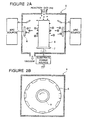
- Fig. 2 illustrates an embodiment of an apparatus for preparing the hard campsite material according to the present invention
- Fig. 2A is an illustrative cross section
- Fig. 2B is an illustrative plane view.
- Fig. 1 illustrates a cross sectional view of a hard composite material for tools according to the present invention, comprising hard heat-resisting film (1) formed on a substrate (2).
- An intermediate layer (3) and a surface layer (4) can be formed optionally.
- Fig. 2 is an illustrative view of an apparatus for producing the hard composite material according to the present invention.
- a plurality of substrates (8) (not shown separately) are held on a rotary holder (7) surrounded by a plurality of targets (6).
- the hard heat-resisting film (1) can be prepared by physical vapour deposition (PVD) technique such as ion-plating which permits to perform surface-treatment of substrate or tool without deteriorating its inherent high wear-resistance and chipping-resistance.
- PVD physical vapour deposition
- the hard heat-resisting film according to the present invention can be produced advantageously by arc ion plating technique in which material elements are ionized at high efficiency and become very reactive.
- a film prepared by the arc ion plating technique possesses very strong adhesion to the substrate.
- At least one intermediate layer (3) having a thickness of 0.05 to 5 ⁇ m is preferably interposed between the substrate (2) and the hard heat-resisting film (1).
- This intermediate layer (3) is preferably made of a material selected from a group comprising nitride, carbide and oxide of IVa, Va and Via elements and their solid solutions.
- the intermediate layer (3) functions to increase adhesion between the hard heat-resisting film (1) and the substrate (2).
- Such intermediate layer is expected to reduce residual stress in the film deposited on a substrate which differs from the film in its property by assuring gradual control of its properties.
- the hard heat-resisting film (1) can be produced by usual arc ion plating technique.
- the present invention resides in such finding that a hard heat-resisting film deposited on CBN sintered article or diamond sintered article improves remarkably cutting performance, wear-resistance and chipping-resistance.
- a compound represented by the general formula: (Ti x Al 1-x )N in which 0.3 ⁇ x ⁇ 0.5 can produce a film improved in properties (hardness and oxidation-resistance) and productivity.
- TiAIN itself is known. Inventor's finding reside in such a fact that TiAlN improve oxidation-resistance without spoiling wear-resistance of hard CBN. A film of TiAIN containing C possesses higher hardness than TiAlN and a film of TiAIN containing O shows improved oxidation-resistance.
- the hard heat-resisting film having a crystal structure of cubic system shows particularly improved hardness and does not spoil wear-resistance of CBN tools.
- the hardness of the hard heat-resisting film further increase because deformation of the hard heat-resisting film according to the present invention is limited at an interface with the substrate because the film is prepared by ion plating technique which ' assures strong adhesion to the substrate.
- the the hard heat-resisting film according to the present invention can have a layered structure comprising more than two compounds or cyclic multi-layered structure.
- the hard heat-resisting film may have a gradient structure in which composition change gradually from the substrate side to the film side.
- Gradient structure can be formed between the substrate and the intermediate layer of the hard heat-resisting film, between the intermediate layer and the hard heat-resisting film, between adjacent the hard heat-resisting films, between the hard heat-resisting film and a surface layer.
- Such gradient structures are advantageously used to solve the problems of separation or crack of films.
- the total thickness of the hard heat-resisting film according to the present invention is not higher than 0.5 ⁇ m, no improvement in wear-resistance is observed.
- the thickness of the intermediate layer is preferably selected in a range between 0.05 and 5 ⁇ m from the view point of productivity.
- a surface or top layer (4) can be formed on the the hard heat-resisting film. The thickness of this top layer (4) is preferably less than 5 ⁇ m. Improvement in wear-resistance and chipping-resistance is not expected over 5 ⁇ m because such thick surface layer peels off and is not desirable from the view point of productivity.
- the super hard composite material according to the present invention is shaped or machined into and advantageously used as cutting tools such as tip, drills and end mills. It is confirmed that tools produced from the hard heat-resisting composite material according to the present invention show surprisingly superior cutting performance and long lives.
- CBN sintered substrate can be selected from following three types of CBN sintered bodies (1) to (3):
- CBN sintered body of the type (I) itself is known and its properties and its production method are described in details in the JP-A-53-77811 .
- CBN sintered body of the type (2) can be prepared by adding TiN to a binder disclosed in the JP-B-52-43846 . Addition of TiN increase adhesion to the hard heat-resisting film of the present invention.
- CBN sintered body of the type (3) can be prepared by adding TiN to a binder disclosed in the JP-A-59-57967 . Addition of TiN increase adhesion to the hard heat-resisting film in this case also.
- the binder consist of at least one member selected from a group comprising nitride, carbide, boride and oxide of IVa, Va and VIa elements and their solid solutions and 5 to 50 % by weight of aluminium and/or aluminium compound and react with CBN at high temperature and pressure during sintering stage to produce such compounds as aluminum boride (AlB 2 ), aluminum nitride (AlN) or the like at an interface or boundary between CBN particle and the binder, which increase bonding force among particles and improve toughness and strength of the sintered body.
- AlB 2 aluminum boride
- AlN aluminum nitride
- the values of "z" in TiN Z and TiC Z are shifted to stoichiometrically excess such side as 0.5 ⁇ z ⁇ 0.85 and 0.65 ⁇ z ⁇ 0.85 respectively to increase free titanium which promote reaction of binder to the CBN.
- wear-resistance and strength of the resulting CBN sintered body is improved by the such reaction products as AlB 2 , AIN and TiB 2 .
- the values of "x" are not higher than 0.5 and 0.65 respectively, packaging of powder become difficult due to exothermic oxidation reaction. On the contrary, no substantial improvement in reactivity between CBN and the binder is expected even if the values of "x" exceeds 0.85.
- a CBN sintered body containing excess amount of aluminum and/or aluminum compound in binder powder will be an ideal base material for hard composite material for tools possessing chipping-resistance and wear-resistance by a coating of the hard heat-resisting film according to the present invention is deposited.
- CBN powder has preferably an average particle size of less than 3 ⁇ m so as to produce CBN sintered body having the transverse rupture strength determined according to JIS standard of higher than 105 kgf/mm 2 .
- the CBN sintered body coated with the hard heat-resisting film according to the present invention can be used in the interrupting hard cutting work of hardened hard steel to which the conventional CBN sintered tools or known CBN tools coated with wear-resisting coating could not be used and satisfactory long tool life which is acceptable in actual uses is obtained.
- the diamond sintered body is preferably selected from following three types;
- the present invention provides the use of a hard composite material for cutting tools for hardened steels improved in strength, tenacity and wear-resistance by depositing a hard heat-resisting film on a CBN sintered body which possesses very high strength, hardness and tenacity, so that tools prepared from the material show very long tool life comparing to known cutting tools and can be used in wider applications.
- Powder of TiN and powder of AlN were mixed at a ratio of 80 : 20 by weight in a pot made of cemented carbide alloy containing balls of the same material to obtain a binder powder.
- the binder powder was mixed with CBN powder at a ratio of 40 : 60 by volume and the resulting powder mixture was packed in a Mo container and sintered at 1,450 °C under a pressure of 5.00 ⁇ 10 9 Pa (50 kb) for 20 minutes.
- the resulting sintered article was shaped into a tip for cutting tool (shape of SNGN 120408) and a hard heat-resisting film was deposited on portions of the tip where cutting takes place by ion-plating technique in vacuum arc-discharge.
- a plurality of targets were set in a vacuum chamber as is shown in Fig. 2 and a plurality of tips were secured on a tip holder arranged at the center of the targets.
- the targets are made of TiAl.
- argon (Ar) gas was introduced to create a pressure of 1.33 Pa (10 -2 Torr) in which the tips were cleaned at a voltage of -1,000 V.
- the tips were heated to 500 °C and argon gas was evacuated.
- Sample No. 1-30 to 1-33 are comparative examples of cutting tips having the conventional coating layers having hard coat layer consisting of TiCN layer and TiN layer prepared on the same tip as Example 1 by ion-plating technique under vacuum arc discharge in usual film forming machine.
- Sample No. 1-33 has a hard coat consisting of TiN layer and Al 2 O 3 layer prepared on the same tip as Example 1 by usual CVD technique.
- the resulting tips was evaluated by cutting test in which a round steel rod (SUJ2) having a hardness of HRC63 was cut along its periphery at a cutting speed of 100 m/min, a depth of cut of 0.2 mm, a feed of 0.1 mm per revolution and for 40 minutes in a dry condition. Results are summarized in Table 1.
- Table 1 (to be continued) sample No intermediate layer (3) hard heat-resiting film (1) surface layer (4) ( ⁇ m) flank wear (mm) mark composition ( ⁇ m) compsiotion thickness ( ⁇ m) crystal structure 1-1 none (Ti 0.1 Al 0.9 )N 3.5 hexasgonal none 0.130 bad 1-2 none (Ti 0.3 ,Al 0.7 )N 3.5 cubic none 0.112 good 1-3 none (Ti 0.5 ,Al 0.5 )N 3.5 cubic none 0.114 good 1-4 none (Ti 0.7 ,Al 0.3 )N 3.5 cubic none 0.120 not good 1-5 none (Ti 0.9, Al 0.1 )N 3.5 cubic none 0.130 bad 1-6 TiN 0.5 (Ti 0.3 ,Al 0.7 )C 3.5 cubic a) 0.105 v.
- TiN 7.0 Ti 0.3 ,Al 0.7 )(N 0.9 O 0.1 ) 2.5 cubic none 0.121 not good 1-24
- TiN 0.4 Ti 0.5 ,Al 0.5 )N 3.3 cubic a) 0.01 0.107 v. good 1-25 TiN 0.4 (Ti 0.5 ,Al 0.5 )N 3.3 cubic a) 0.05 0.105 v. good 1-26 TiN 0.4 (Ti 0.5 ,Al 0.5 )N 3.3 cubic a) 1.0 0.106 v, good 1-27 TiN 0.4 (Ti 0.5 ,Al 0.5 )N 3.3 cubic a) 5.0 0.107 v.
- Example 2 Procedure of Example 1 was repeated but the content (vol %) of CBN in the substrate and compositions of binder (% by weight) were changed to Table 2.
- X-ray diffraction patterns of the resulting sintered articles revealed existence of inevitable contaminations which were thought to be ⁇ -Al 2 O 3 , WC and Co.
- the resulting CBN sintered body was shaped into a tip for cutting tool and an intermediate layer of TiN having a thickness of 0.5 ⁇ m was deposited on portions of the tip where cutting participate by usual PVD technique in the same apparatus as Example 1 and then a hard heat-resisting film of (Ti 0.3 Al 0.7 ) N was deposited at a total thickness of 5.6 ⁇ m. Finally, a top layer of Ti (C 0.5 N 0.5 ) was deposited to a thickness of 0.2 ⁇ m.
- Time until damage in Table 2 is time duration until the tool was damaged (min) which was determined when a round steel rod of hardened SKD 11 of HRC hardness 56 having four U-grooves on its periphery was cut at a cutting speed of 100 m/min, a depth of cut of 0.2 mm, a feed of 0.1 mm per revolution in a dry condition.
- Example 2 Procedure of Example 1 was repeated but the CBN sintered bodies were replaced by diamond sintered bodies having the content (vol %) of diamond and compositions of binder (% by weight) shown in Table 3.
- a disk of Co was placed on a bottom of a Mo container in which the powder mixture was then packed.
- the resulting assembly was sintered at 1,450 °C under a pressure of 55 kb for 20 min.
- the resulting diamond sintered body was shaped into a tip for cutting tool and, on portions of the tip where cutting participate, the same intermediate layer (TiN; 0.5 ⁇ m), hard heat-resisting film [(Ti 0.3 Al 0.7 )N; 5.6 ⁇ m ] and top layer of [Ti (C 0.5 N 0.5 ); 0.2 ⁇ m] were deposited by the same ion plating technique as Example 1.
- a comparative tip is CBN sintered body used in Example 1 having no hard heat-resisting layer according to the present invention and the other comparative tips are diamond sintered bodies having no hard heat-resisting layer according to the present invention.
Landscapes
- Chemical & Material Sciences (AREA)
- Engineering & Computer Science (AREA)
- Ceramic Engineering (AREA)
- Materials Engineering (AREA)
- Organic Chemistry (AREA)
- Structural Engineering (AREA)
- Inorganic Chemistry (AREA)
- Metallurgy (AREA)
- Mechanical Engineering (AREA)
- Chemical Kinetics & Catalysis (AREA)
- Cutting Tools, Boring Holders, And Turrets (AREA)
- Ceramic Products (AREA)
- Physical Vapour Deposition (AREA)
Claims (8)
- Verwendung eines harten Verbundwerkstoffs für Schneidwerkzeuge für gehärtete Stähle, wobei der harte Verbundwerkstoff ein Substrat aus einem CBN-Sinterkörper, enthaltend mehr als 20 Vol.-% kubisches Bornitrid (CBN), umfasst, dadurch gekennzeichnet, dass das Substrat mindestens eine Schicht aus einem harten wärmebeständigen Film, der hauptsächlich aus Ti, Al und mindestens einem Element, gewählt aus einer Gruppe umfassend C, N und O, besteht, auf einem Teil oder Teilen des Substrats aufweist, wo das Schneiden stattfindet, und dass der Sinterkörper gewählt ist aus den folgenden drei Typen von CBN-Sinterkörpern (1) bis (3):(1) einem CBN-Sinterkörper, der durch Sintern bei hohem Druck von 30 bis 90 Vol.-% kubischem Bornitrid (CBN)-Pulver und einem den Rest bildenden Bindemittelpulver, umfassend mindestens einen Bestandteil gewählt aus einer Gruppe umfassend Nitrid, Carbid, Borid und Oxid von IVa-, Va- und Vla-Elementen und ihre festen Lösungen und Aluminium und/oder eine Aluminiumverbindung, und unvermeidbare Verunreinigungen, erhalten wird;(2) einem CBN-Sinterkörper, der durch Hochdrucksintern von 40 bis 95 Vol.-% kubischem Bornitrid (CBN)-Pulver und einem den Rest bildenden Bindemittelpulver, umfassend 1 bis 50 Gew.-% TiN, mindestens einen Bestandteil, gewählt aus einer Gruppe umfassend Co, Ni und WC, Aluminium und/oder eine Aluminiumverbindung und unvermeidbare Verunreinigungen, erhalten wird; und(3) einem CBN-Sinterkörper, der durch Hochdrucksintern von mehr als 90 Vol.-% kubischem Bornitrid (CBN)-Pulver und einem den Rest bildenden Bindemittelpulver, umfassend Borid von la- oder Ila-Elementen, TiN und unvermeidbare Verunreinigungen, erhalten wird,wobei der harte wärmebeständige Film eine Kristallstruktur des kubischen Systems aufweist und
wobei der harte wärmebeständige Film eine Dicke von 0,5 bis 15 µm aufweist. - Verwendung des Verbundwerkstoffs nach Anspruch 1, wobei der harte wärmebeständige Film aus einer Verbindung gefertigt ist, die durch die allgemeine Formel:
(TixAl1-x)N
wiedergegeben wird, in welcher gilt: 0,3 ≤ x ≤ 0,5. - Verwendung des Verbundwerkstoffs nach Anspruch 1 oder 2, wobei eine Zwischenschicht mit einer Dicke von 0,05 bis 5 µm, welche aus mindestens einer Verbindung von mindestens einem Element, gewählt aus einer Gruppe umfassend IVa-, Va- und VIa-Elemente, und mindestens einem Element, gewählt aus einer Gruppe umfassend C, N und O, gefertigt ist, zwischen das Substrat und den harten wärmebeständigen Film eingeschoben ist.
- Verwendung des Verbundwerkstoffs nach einem der Ansprüche 1 bis 3, wobei eine Oberflächenschicht mit einer Dicke von 0,05 bis 5 µm, die aus mindestens einer Verbindung von mindestens einem Element, gewählt aus einer Gruppe, umfassend IVa-, Va- und VIa-Elemente, und mindestens einem Element, gewählt aus einer Gruppe umfassend C, N und O, gefertigt ist, auf einer äußeren Oberfläche des harten wärmebeständigen Films abgeschieden ist.
- Verwendung des Verbundwerkstoffs nach einem der Ansprüche 1 bis 4, wobei das Substrat wie in (1) in Anspruch 1 definiert ist, wobei das Bindemittel aus 50 bis 95 Gew.-% von mindestens einem Bestandteil, gewählt aus einer Gruppe umfassend TiC, TiN, (TiM)C, (TiM)N und (TiM)CN, wobei M ein Übergangsmetall, gewählt aus IVa-, Va- und VIa-Elementen mit Ausnahme von Ti ist, und 5 bis 50 Gew.-% Aluminium und/oder einer Aluminiumverbindung besteht.
- Verwendung des Verbundwerkstoffs nach Anspruch 5, wobei das Bindemittel aus 50 bis 80 Gew.-% TiNz, wobei 0,5 ≤ z ≤ 0,85, 15 bis 50 Gew.-% Aluminium und/oder einer Aluminiumverbindung und unvermeidbaren Verunreinigungen besteht, und die Biegezähigkeit bzw. Biegebruchfestigkeit (transverse rupture strength) des CBN-Sinterkörpers, bestimmt gemäß JIS-Norm, mehr als 1,08 x 10⁹ Pa (110 kgf/mm2) beträgt.
- Verwendung des Verbundwerkstoffs nach einem der Ansprüche 1 bis 4, wobei das Substrat wie in (2) in Anspruch 1 definiert ist, das CBN-Pulver eine Teilchengröße von weniger als 3 µm aufweist und die Biegezähigkeit bzw. Biegebruchfestigkeit des CBN-Sinterkörpers, bestimmt gemäß JIS-Norm, mehr als 1,03 x 10⁹ Pa (105 kgf/mm2) beträgt.
- Verwendung des Verbundwerkstoffs nach einem der Ansprüche 1 bis 4, wobei das Substrat wie in (3) in Anspruch 1 definiert ist, wobei das Bindemittel 1 bis 50 Gew.-% TiN und Borid von la- oder IIa-Elementen enthält.
Applications Claiming Priority (3)
| Application Number | Priority Date | Filing Date | Title |
|---|---|---|---|
| JP28737494 | 1994-10-27 | ||
| JP287374/94 | 1994-10-27 | ||
| JP28737494A JP3866305B2 (ja) | 1994-10-27 | 1994-10-27 | 工具用複合高硬度材料 |
Publications (4)
| Publication Number | Publication Date |
|---|---|
| EP0709353A2 EP0709353A2 (de) | 1996-05-01 |
| EP0709353A3 EP0709353A3 (de) | 1998-10-28 |
| EP0709353B1 EP0709353B1 (de) | 2002-06-19 |
| EP0709353B2 true EP0709353B2 (de) | 2007-11-28 |
Family
ID=17716539
Family Applications (1)
| Application Number | Title | Priority Date | Filing Date |
|---|---|---|---|
| EP95402407A Expired - Lifetime EP0709353B2 (de) | 1994-10-27 | 1995-10-26 | Harter Verbundwerkstoff für Werkzeuge |
Country Status (5)
| Country | Link |
|---|---|
| US (1) | US5853873A (de) |
| EP (1) | EP0709353B2 (de) |
| JP (1) | JP3866305B2 (de) |
| CA (1) | CA2161611C (de) |
| DE (1) | DE69527124T3 (de) |
Cited By (1)
| Publication number | Priority date | Publication date | Assignee | Title |
|---|---|---|---|---|
| US10184187B2 (en) | 2013-08-16 | 2019-01-22 | Kennametal Inc. | Low stress hard coatings and applications thereof |
Families Citing this family (70)
| Publication number | Priority date | Publication date | Assignee | Title |
|---|---|---|---|---|
| US6613410B1 (en) * | 1999-09-23 | 2003-09-02 | National Label Company | Extended wrap label |
| EP0852167A1 (de) * | 1997-01-07 | 1998-07-08 | General Electric Company | Polykristalline hochabrasive Werkzeuge aus beschichtetem kubischen Bornitrid |
| JP3031907B2 (ja) * | 1998-03-16 | 2000-04-10 | 日立ツール株式会社 | 多層膜被覆部材 |
| KR100614177B1 (ko) | 1999-02-12 | 2006-08-21 | 스미토모덴키고교가부시키가이샤 | 고내크레이터성 고강도 소결체 |
| US6599062B1 (en) | 1999-06-11 | 2003-07-29 | Kennametal Pc Inc. | Coated PCBN cutting inserts |
| US6416560B1 (en) | 1999-09-24 | 2002-07-09 | 3M Innovative Properties Company | Fused abrasive bodies comprising an oxygen scavenger metal |
| CA2327092C (en) * | 1999-12-03 | 2004-04-20 | Sumitomo Electric Industries, Ltd. | Coated pcbn cutting tools |
| JP3637883B2 (ja) | 2000-08-31 | 2005-04-13 | 住友電気工業株式会社 | 表面被覆窒化硼素焼結体工具 |
| JP3637882B2 (ja) | 2000-08-31 | 2005-04-13 | 住友電気工業株式会社 | 表面被覆窒化硼素焼結体工具 |
| US6575353B2 (en) * | 2001-02-20 | 2003-06-10 | 3M Innovative Properties Company | Reducing metals as a brazing flux |
| US6962751B2 (en) | 2001-06-13 | 2005-11-08 | Sumitomo Electric Industries, Ltd. | Amorphous carbon coated tools and method of producing the same |
| US6881475B2 (en) | 2001-06-13 | 2005-04-19 | Sumitomo Electric Industries, Ltd | Amorphous carbon coated tool and fabrication method thereof |
| US20030096142A1 (en) * | 2001-11-19 | 2003-05-22 | Muncie Power Products, Inc. | Dual coated cubic boron nitride cutting tool and method of employing same |
| US6660133B2 (en) | 2002-03-14 | 2003-12-09 | Kennametal Inc. | Nanolayered coated cutting tool and method for making the same |
| SE526337C2 (sv) * | 2002-07-16 | 2005-08-23 | Seco Tools Ab | PVD-belagt skärverktyg med åtminstone ett skikt av (Ti, A1) (O, N) samt metod för att framställa detsamma |
| US20040146616A1 (en) * | 2003-01-29 | 2004-07-29 | Thorson James S. | Method and system for ultrasonic surface modification of food products |
| CA2531028C (en) * | 2003-06-27 | 2009-07-14 | Sumitomo Electric Industries, Ltd. | Surface-coated high hardness material for tool |
| EP1574594B1 (de) * | 2004-03-12 | 2013-04-03 | Sulzer Metaplas GmbH | Eine kohlenstoffhaltige harte Beschichtung und ein Verfahren zur Beschichtung eines Substrats mit einer harten Beschichtung. |
| IL166652A (en) | 2004-03-12 | 2010-11-30 | Sulzer Metaplas Gmbh | Carbon containing hard coating and method for depositing a hard coating onto a substrate |
| US7694757B2 (en) * | 2005-02-23 | 2010-04-13 | Smith International, Inc. | Thermally stable polycrystalline diamond materials, cutting elements incorporating the same and bits incorporating such cutting elements |
| JP2006247779A (ja) * | 2005-03-10 | 2006-09-21 | Tungaloy Corp | 被覆cBN基焼結体切削工具 |
| US7493973B2 (en) | 2005-05-26 | 2009-02-24 | Smith International, Inc. | Polycrystalline diamond materials having improved abrasion resistance, thermal stability and impact resistance |
| US7758976B2 (en) | 2005-10-04 | 2010-07-20 | Sumitomo Electric Hardmetal Corp. | cBN sintered body for high surface integrity machining and cBN sintered body cutting tool |
| CA2571470C (en) | 2005-11-18 | 2013-02-05 | Sumitomo Electric Hardmetal Corp. | Cbn sintered body for high surface integrity machining, cbn sintered body cutting tool, and cutting method using the same |
| JP4985919B2 (ja) | 2005-12-22 | 2012-07-25 | 三菱マテリアル株式会社 | 高硬度鋼の高速切削加工で優れた仕上げ面精度を長期にわたって発揮する表面被覆立方晶窒化ほう素基超高圧焼結材料製切削工具 |
| EP2000237A1 (de) * | 2006-03-28 | 2008-12-10 | Kyocera Corporation | Oberflächenbeschichtetes werkzeug |
| JP5462622B2 (ja) * | 2006-04-21 | 2014-04-02 | エレメント シックス (プロダクション)(プロプライエタリィ) リミテッド | 立方晶窒化ホウ素複合材料及び工具 |
| JP5005262B2 (ja) | 2006-05-26 | 2012-08-22 | 三菱マテリアル株式会社 | 高硬度鋼の高速切削加工できわめて優れた仕上げ面精度を長期にわたって発揮する表面被覆立方晶窒化ほう素基超高圧焼結材料製切削工具 |
| US9097074B2 (en) | 2006-09-21 | 2015-08-04 | Smith International, Inc. | Polycrystalline diamond composites |
| DE102007046380B9 (de) * | 2006-09-27 | 2012-12-06 | Kyocera Corporation | Schneidwerkzeug |
| CN101595075B (zh) | 2007-01-30 | 2013-07-03 | 住友电工硬质合金株式会社 | 复合烧结体 |
| CA2619547C (en) | 2007-02-06 | 2016-05-17 | Smith International, Inc. | Polycrystalline diamond constructions having improved thermal stability |
| US7942219B2 (en) | 2007-03-21 | 2011-05-17 | Smith International, Inc. | Polycrystalline diamond constructions having improved thermal stability |
| WO2008142656A1 (en) * | 2007-05-22 | 2008-11-27 | Element Six Limited | Coated cbn |
| DE102007000512B3 (de) * | 2007-10-16 | 2009-01-29 | Fraunhofer-Gesellschaft zur Förderung der angewandten Forschung e.V. | Hartstoffbeschichtete Körper und Verfahren zu deren Herstellung |
| US9297211B2 (en) | 2007-12-17 | 2016-03-29 | Smith International, Inc. | Polycrystalline diamond construction with controlled gradient metal content |
| RU2010140369A (ru) * | 2008-03-04 | 2012-04-10 | Ирвин Индастриал Тул Компани (Us) | Инструменты, имеющие рабочие поверхности из уплотненного порошкового металла, и способ |
| US8236411B2 (en) | 2008-03-26 | 2012-08-07 | Kyocera Corporation | Cutting tool |
| US20110117368A1 (en) * | 2008-07-16 | 2011-05-19 | Hideaki Matsubara | Hard Powder, Process for Preparing Hard Powder and Sintered Hard Alloy |
| WO2011109016A1 (en) * | 2009-03-03 | 2011-09-09 | Diamond Innovations, Inc. | Thick thermal barrier coating for superabrasive tool |
| JP2013521134A (ja) * | 2009-03-03 | 2013-06-10 | ダイヤモンド イノベイションズ インコーポレーテッド | 超研磨工具用の厚い断熱層コーティング |
| JP5559575B2 (ja) | 2009-03-10 | 2014-07-23 | 株式会社タンガロイ | サーメットおよび被覆サーメット |
| JP5293330B2 (ja) * | 2009-03-26 | 2013-09-18 | 三菱マテリアル株式会社 | 表面被覆立方晶窒化ほう素基超高圧焼結材料製切削工具 |
| US8590130B2 (en) | 2009-05-06 | 2013-11-26 | Smith International, Inc. | Cutting elements with re-processed thermally stable polycrystalline diamond cutting layers, bits incorporating the same, and methods of making the same |
| CA2760944A1 (en) | 2009-05-06 | 2010-11-11 | Smith International, Inc. | Methods of making and attaching tsp material for forming cutting elements, cutting elements having such tsp material and bits incorporating such cutting elements |
| GB2483590B8 (en) | 2009-06-18 | 2014-07-23 | Smith International | Polycrystalline diamond cutting elements with engineered porosity and method for manufacturing such cutting elements |
| WO2010150335A1 (ja) | 2009-06-22 | 2010-12-29 | 株式会社タンガロイ | 被覆立方晶窒化硼素焼結体工具 |
| US8277958B2 (en) | 2009-10-02 | 2012-10-02 | Kennametal Inc. | Aluminum titanium nitride coating and method of making same |
| US8505654B2 (en) | 2009-10-09 | 2013-08-13 | Element Six Limited | Polycrystalline diamond |
| EP2514552A4 (de) * | 2009-12-17 | 2017-04-05 | Sumitomo Electric Industries, Ltd. | Beschichtetes drehwerkzeug |
| JPWO2011129422A1 (ja) | 2010-04-16 | 2013-07-18 | 株式会社タンガロイ | 被覆cBN焼結体 |
| US8673435B2 (en) | 2010-07-06 | 2014-03-18 | Tungaloy Corporation | Coated cBN sintered body tool |
| CN103228383B (zh) * | 2010-11-26 | 2016-08-03 | 住友电工硬质合金株式会社 | 表面被覆烧结体 |
| WO2012079769A1 (en) | 2010-12-17 | 2012-06-21 | Seco Tools Ab | Coated cubic boron nitride tool for machining applications |
| US8409702B2 (en) | 2011-02-07 | 2013-04-02 | Kennametal Inc. | Cubic aluminum titanium nitride coating and method of making same |
| US8507082B2 (en) | 2011-03-25 | 2013-08-13 | Kennametal Inc. | CVD coated polycrystalline c-BN cutting tools |
| US9028953B2 (en) | 2013-01-11 | 2015-05-12 | Kennametal Inc. | CVD coated polycrystalline c-BN cutting tools |
| US9103036B2 (en) | 2013-03-15 | 2015-08-11 | Kennametal Inc. | Hard coatings comprising cubic phase forming compositions |
| US9168664B2 (en) | 2013-08-16 | 2015-10-27 | Kennametal Inc. | Low stress hard coatings and applications thereof |
| JP6115824B2 (ja) * | 2013-09-06 | 2017-04-19 | 三菱マテリアル株式会社 | サーミスタ用金属窒化物材料及びその製造方法並びにサーミスタセンサ |
| JP6928218B2 (ja) | 2015-12-25 | 2021-09-01 | 三菱マテリアル株式会社 | 表面被覆立方晶窒化ホウ素焼結体工具 |
| JP6850980B2 (ja) | 2016-03-07 | 2021-03-31 | 三菱マテリアル株式会社 | 表面被覆立方晶窒化ホウ素焼結体工具 |
| WO2018198421A1 (ja) | 2017-04-25 | 2018-11-01 | 住友電気工業株式会社 | 切削工具およびその製造方法 |
| US12410103B2 (en) * | 2019-07-18 | 2025-09-09 | Sumitomo Electric Industries, Ltd. | Cubic boron nitride sintered material and cutting tool |
| JP6863649B1 (ja) | 2019-08-06 | 2021-04-21 | 住友電工ハードメタル株式会社 | 切削工具 |
| EP3960341A4 (de) | 2019-08-06 | 2022-06-29 | Sumitomo Electric Hardmetal Corp. | Schneidwerkzeug |
| TWI865802B (zh) * | 2020-08-20 | 2024-12-11 | 美商工藝技術公司 | 引線接合毛細管 |
| CN117480023A (zh) | 2021-06-30 | 2024-01-30 | 住友电工硬质合金株式会社 | 切削工具 |
| WO2025224238A1 (en) * | 2024-04-26 | 2025-10-30 | Ab Sandvik Coromant | A coated cutting tool |
| CN119194354B (zh) * | 2024-09-27 | 2026-03-20 | 广州博森盾技术有限公司 | 立方氮化硼薄膜结构、切削工具及其制造方法与设备 |
Citations (5)
| Publication number | Priority date | Publication date | Assignee | Title |
|---|---|---|---|---|
| JPS61230803A (ja) † | 1985-04-03 | 1986-10-15 | Nippon Oil & Fats Co Ltd | 切削工具 |
| JPS6256565A (ja) † | 1985-09-06 | 1987-03-12 | Mitsubishi Metal Corp | 耐摩耗性のすぐれた表面被覆硬質部材 |
| JPH04201003A (ja) † | 1990-11-28 | 1992-07-22 | Mitsubishi Materials Corp | 表面被覆セラミックス製切削工具 |
| JPH0569205A (ja) † | 1991-09-12 | 1993-03-23 | Sumitomo Electric Ind Ltd | セラミツクス切削工具 |
| US5308367A (en) † | 1991-06-13 | 1994-05-03 | Julien D Lynn | Titanium-nitride and titanium-carbide coated grinding tools and method therefor |
Family Cites Families (24)
| Publication number | Priority date | Publication date | Assignee | Title |
|---|---|---|---|---|
| NL174715C (nl) | 1971-07-01 | 1984-08-01 | Gen Electric | Werkwijze ter vervaardiging van een slijplichaam, alsmede snijgereedschap voorzien van een volgens deze werkwijze vervaardigd inzetstuk. |
| AU512633B2 (en) * | 1976-12-21 | 1980-10-23 | Sumitomo Electric Industries, Ltd. | Sintered tool |
| JPS5377811A (en) | 1976-12-21 | 1978-07-10 | Sumitomo Electric Ind Ltd | Sintered material for tools of high hardness and its preparation |
| GB2048956B (en) * | 1979-03-29 | 1983-02-16 | Sumitomo Electric Industries | Sintered compact for a machining tool |
| JPS5779169A (en) * | 1980-11-06 | 1982-05-18 | Sumitomo Electric Ind Ltd | Physical vapor deposition method |
| IL63802A (en) * | 1981-09-11 | 1984-10-31 | Iscar Ltd | Sintered hard metal products having a multi-layer wear-resistant coating |
| US4447263A (en) * | 1981-12-22 | 1984-05-08 | Mitsubishi Kinzoku Kabushiki Kaisha | Blade member of cermet having surface reaction layer and process for producing same |
| AT377786B (de) * | 1981-12-24 | 1985-04-25 | Plansee Metallwerk | Verschleissteil, insbesondere hartmetall -schneideinsatz zur spanabhebenden bearbeitung |
| JPS6028782B2 (ja) | 1982-09-27 | 1985-07-06 | 科学技術庁無機材質研究所長 | 透光性立方晶窒化ほう素緻密体の製造法 |
| US4540596A (en) * | 1983-05-06 | 1985-09-10 | Smith International, Inc. | Method of producing thin, hard coating |
| JPS61183187A (ja) * | 1985-02-06 | 1986-08-15 | 住友電気工業株式会社 | 被覆硬質焼結体 |
| US4714660A (en) * | 1985-12-23 | 1987-12-22 | Fansteel Inc. | Hard coatings with multiphase microstructures |
| JPH0621313B2 (ja) * | 1985-12-28 | 1994-03-23 | 住友電気工業株式会社 | 高硬度工具用焼結体およびその製造方法 |
| CH669347A5 (de) * | 1986-05-28 | 1989-03-15 | Vni Instrument Inst | |
| JPH0725619B2 (ja) * | 1987-10-06 | 1995-03-22 | 三菱マテリアル株式会社 | 切削工具用表面被覆立方晶窒化ほう素基超高圧焼結材料 |
| JPH0725611B2 (ja) * | 1987-10-06 | 1995-03-22 | 三菱マテリアル株式会社 | 切削工具用表面被覆立方晶窒化ほう素基超高圧焼結材料 |
| JPH0694580B2 (ja) * | 1988-12-14 | 1994-11-24 | 住友電気工業株式会社 | 高精度加工工具用焼結体 |
| JP3132843B2 (ja) * | 1991-04-23 | 2001-02-05 | 東芝タンガロイ株式会社 | 高靭性高圧相窒化硼素焼結体 |
| DE4126851A1 (de) * | 1991-08-14 | 1993-02-18 | Krupp Widia Gmbh | Werkzeug mit verschleissfester schneide aus kubischem bornitrid oder polykristallinem kubischem bornitrid, verfahren zu dessen herstellung sowie dessen verwendung |
| JPH05186272A (ja) * | 1992-01-09 | 1993-07-27 | Toshiba Tungaloy Co Ltd | 複合高密度相窒化ホウ素焼結体 |
| JP3321824B2 (ja) * | 1992-04-16 | 2002-09-09 | 住友電気工業株式会社 | 高硬度工具用焼結体 |
| US5326380A (en) * | 1992-10-26 | 1994-07-05 | Smith International, Inc. | Synthesis of polycrystalline cubic boron nitride |
| US5271749A (en) * | 1992-11-03 | 1993-12-21 | Smith International, Inc. | Synthesis of polycrystalline cubic boron nitride |
| JPH0724606A (ja) * | 1993-07-06 | 1995-01-27 | Mitsubishi Materials Corp | 耐欠損性のすぐれた表面複合立方晶窒化ほう素基超高圧焼結材料製切削工具 |
-
1994
- 1994-10-27 JP JP28737494A patent/JP3866305B2/ja not_active Expired - Lifetime
-
1995
- 1995-10-26 EP EP95402407A patent/EP0709353B2/de not_active Expired - Lifetime
- 1995-10-26 DE DE69527124T patent/DE69527124T3/de not_active Expired - Lifetime
- 1995-10-27 CA CA002161611A patent/CA2161611C/en not_active Expired - Lifetime
- 1995-10-27 US US08/549,168 patent/US5853873A/en not_active Expired - Lifetime
Patent Citations (5)
| Publication number | Priority date | Publication date | Assignee | Title |
|---|---|---|---|---|
| JPS61230803A (ja) † | 1985-04-03 | 1986-10-15 | Nippon Oil & Fats Co Ltd | 切削工具 |
| JPS6256565A (ja) † | 1985-09-06 | 1987-03-12 | Mitsubishi Metal Corp | 耐摩耗性のすぐれた表面被覆硬質部材 |
| JPH04201003A (ja) † | 1990-11-28 | 1992-07-22 | Mitsubishi Materials Corp | 表面被覆セラミックス製切削工具 |
| US5308367A (en) † | 1991-06-13 | 1994-05-03 | Julien D Lynn | Titanium-nitride and titanium-carbide coated grinding tools and method therefor |
| JPH0569205A (ja) † | 1991-09-12 | 1993-03-23 | Sumitomo Electric Ind Ltd | セラミツクス切削工具 |
Non-Patent Citations (2)
| Title |
|---|
| Ikeda T. and Satoh H; Journal of Japan Institute of Metals 1993, 57, p. 919-925 † |
| Yamada et al., Transactions of the Japan Society of Mechanical Engineers C, 1994 - 9, 60; p. 14-18 † |
Cited By (1)
| Publication number | Priority date | Publication date | Assignee | Title |
|---|---|---|---|---|
| US10184187B2 (en) | 2013-08-16 | 2019-01-22 | Kennametal Inc. | Low stress hard coatings and applications thereof |
Also Published As
| Publication number | Publication date |
|---|---|
| EP0709353B1 (de) | 2002-06-19 |
| JPH08119774A (ja) | 1996-05-14 |
| DE69527124T3 (de) | 2008-09-11 |
| DE69527124D1 (de) | 2002-07-25 |
| EP0709353A3 (de) | 1998-10-28 |
| CA2161611C (en) | 1999-01-05 |
| DE69527124T2 (de) | 2003-02-27 |
| JP3866305B2 (ja) | 2007-01-10 |
| EP0709353A2 (de) | 1996-05-01 |
| US5853873A (en) | 1998-12-29 |
| CA2161611A1 (en) | 1996-04-28 |
Similar Documents
| Publication | Publication Date | Title |
|---|---|---|
| EP0709353B2 (de) | Harter Verbundwerkstoff für Werkzeuge | |
| EP0701982B1 (de) | Mehrschichtfilm aus ultrafeinen Partikeln und harter Verbundwerkstoff für Werkzeuge, die diesen Film enthalten | |
| EP0695731B1 (de) | Überharter Verbundwerkstoff für Werkzeuge | |
| EP1122226B1 (de) | Beschichtete PCBN-Schneidewerzeuge | |
| EP2446987B1 (de) | Werkzeug mit beschichtetem würfelförmigem bornitrid-sinterkörper | |
| EP1382709B1 (de) | Beschichtetes Werkzeug | |
| TWI333435B (en) | Carbide cutting insert | |
| EP2636764B1 (de) | Nanolaminiertes und beschichtetes Schneidewerkzeug | |
| EP1786954B1 (de) | Pvd-beschichtete rutheniumhaltige schneiderwerkzeuge | |
| EP2098611B1 (de) | Überzugsbeschichtetes Schneidewerkzeug | |
| EP0592986A1 (de) | Ultradünnes Filmlaminat | |
| JP3743984B2 (ja) | 工具用複合高硬度材料 | |
| JP3402146B2 (ja) | 硬質被覆層がすぐれた密着性を有する表面被覆超硬合金製エンドミル | |
| JP3374599B2 (ja) | 硬質耐摩耗層複合被覆切削工具 | |
| US7022403B1 (en) | Adhesive composite coating for diamond and diamond-containing materials and method for producing said coating | |
| JPH10237650A (ja) | Wc基超硬合金およびその製造方法 | |
| JP4883475B2 (ja) | 高硬度鋼の高速切削加工で硬質被覆層がすぐれた耐摩耗性を発揮する表面被覆立方晶窒化ほう素基超高圧焼結材料製切削工具 | |
| JP3266047B2 (ja) | 硬質被覆層がすぐれた層間密着性を有する表面被覆超硬合金製切削工具 | |
| JPH0873289A (ja) | 工具用複合高硬度材料 | |
| JP4004026B2 (ja) | 希土類酸化物を含有する硬質膜を被覆した被覆部材 | |
| EP2714387B1 (de) | Verfahren zur herstellung einer mehrschichtigen beschichtung mit kubischen bornitridpartikeln | |
| JP3371796B2 (ja) | 耐欠損性のすぐれた表面被覆超硬合金製切削工具 | |
| JPH11350111A (ja) | 超硬質膜被覆工具部材 | |
| JP3371823B2 (ja) | 硬質被覆層がすぐれた層間密着性を有する表面被覆超硬合金製切削工具 | |
| JPH04322903A (ja) | 硬質相密着性のすぐれた超高圧焼結材料製切削工具 |
Legal Events
| Date | Code | Title | Description |
|---|---|---|---|
| PUAI | Public reference made under article 153(3) epc to a published international application that has entered the european phase |
Free format text: ORIGINAL CODE: 0009012 |
|
| AK | Designated contracting states |
Kind code of ref document: A2 Designated state(s): DE FR GB IT SE |
|
| PUAL | Search report despatched |
Free format text: ORIGINAL CODE: 0009013 |
|
| AK | Designated contracting states |
Kind code of ref document: A3 Designated state(s): DE FR GB IT SE |
|
| 17P | Request for examination filed |
Effective date: 19981215 |
|
| 17Q | First examination report despatched |
Effective date: 19991130 |
|
| GRAG | Despatch of communication of intention to grant |
Free format text: ORIGINAL CODE: EPIDOS AGRA |
|
| GRAG | Despatch of communication of intention to grant |
Free format text: ORIGINAL CODE: EPIDOS AGRA |
|
| GRAH | Despatch of communication of intention to grant a patent |
Free format text: ORIGINAL CODE: EPIDOS IGRA |
|
| GRAH | Despatch of communication of intention to grant a patent |
Free format text: ORIGINAL CODE: EPIDOS IGRA |
|
| GRAH | Despatch of communication of intention to grant a patent |
Free format text: ORIGINAL CODE: EPIDOS IGRA |
|
| GRAA | (expected) grant |
Free format text: ORIGINAL CODE: 0009210 |
|
| AK | Designated contracting states |
Kind code of ref document: B1 Designated state(s): DE FR GB IT SE |
|
| REG | Reference to a national code |
Ref country code: GB Ref legal event code: FG4D |
|
| REF | Corresponds to: |
Ref document number: 69527124 Country of ref document: DE Date of ref document: 20020725 |
|
| ET | Fr: translation filed | ||
| PLBQ | Unpublished change to opponent data |
Free format text: ORIGINAL CODE: EPIDOS OPPO |
|
| PLBI | Opposition filed |
Free format text: ORIGINAL CODE: 0009260 |
|
| PLBF | Reply of patent proprietor to notice(s) of opposition |
Free format text: ORIGINAL CODE: EPIDOS OBSO |
|
| 26 | Opposition filed |
Opponent name: MITSUBISHI MATERIALS CORPORATION Effective date: 20030319 |
|
| PLAX | Notice of opposition and request to file observation + time limit sent |
Free format text: ORIGINAL CODE: EPIDOSNOBS2 |
|
| PLBB | Reply of patent proprietor to notice(s) of opposition received |
Free format text: ORIGINAL CODE: EPIDOSNOBS3 |
|
| APBP | Date of receipt of notice of appeal recorded |
Free format text: ORIGINAL CODE: EPIDOSNNOA2O |
|
| APBQ | Date of receipt of statement of grounds of appeal recorded |
Free format text: ORIGINAL CODE: EPIDOSNNOA3O |
|
| APAA | Appeal reference recorded |
Free format text: ORIGINAL CODE: EPIDOS REFN |
|
| APAH | Appeal reference modified |
Free format text: ORIGINAL CODE: EPIDOSCREFNO |
|
| APBU | Appeal procedure closed |
Free format text: ORIGINAL CODE: EPIDOSNNOA9O |
|
| PUAH | Patent maintained in amended form |
Free format text: ORIGINAL CODE: 0009272 |
|
| STAA | Information on the status of an ep patent application or granted ep patent |
Free format text: STATUS: PATENT MAINTAINED AS AMENDED |
|
| 27A | Patent maintained in amended form |
Effective date: 20071128 |
|
| AK | Designated contracting states |
Kind code of ref document: B2 Designated state(s): DE FR GB IT SE |
|
| REG | Reference to a national code |
Ref country code: SE Ref legal event code: RPEO |
|
| ET3 | Fr: translation filed ** decision concerning opposition | ||
| PGFP | Annual fee paid to national office [announced via postgrant information from national office to epo] |
Ref country code: SE Payment date: 20141013 Year of fee payment: 20 Ref country code: DE Payment date: 20141023 Year of fee payment: 20 Ref country code: GB Payment date: 20141022 Year of fee payment: 20 Ref country code: FR Payment date: 20141008 Year of fee payment: 20 |
|
| PGFP | Annual fee paid to national office [announced via postgrant information from national office to epo] |
Ref country code: IT Payment date: 20140908 Year of fee payment: 20 |
|
| REG | Reference to a national code |
Ref country code: DE Ref legal event code: R071 Ref document number: 69527124 Country of ref document: DE |
|
| REG | Reference to a national code |
Ref country code: GB Ref legal event code: PE20 Expiry date: 20151025 |
|
| REG | Reference to a national code |
Ref country code: SE Ref legal event code: EUG |
|
| PG25 | Lapsed in a contracting state [announced via postgrant information from national office to epo] |
Ref country code: GB Free format text: LAPSE BECAUSE OF EXPIRATION OF PROTECTION Effective date: 20151025 |