EP0709545A2 - Dünnlochbohrsystem für tiefes Wasser - Google Patents
Dünnlochbohrsystem für tiefes Wasser Download PDFInfo
- Publication number
- EP0709545A2 EP0709545A2 EP95850188A EP95850188A EP0709545A2 EP 0709545 A2 EP0709545 A2 EP 0709545A2 EP 95850188 A EP95850188 A EP 95850188A EP 95850188 A EP95850188 A EP 95850188A EP 0709545 A2 EP0709545 A2 EP 0709545A2
- Authority
- EP
- European Patent Office
- Prior art keywords
- drilling
- arrangement
- subsea
- shall
- ctbop
- Prior art date
- Legal status (The legal status is an assumption and is not a legal conclusion. Google has not performed a legal analysis and makes no representation as to the accuracy of the status listed.)
- Granted
Links
- 238000005553 drilling Methods 0.000 title claims abstract description 99
- XLYOFNOQVPJJNP-UHFFFAOYSA-N water Substances O XLYOFNOQVPJJNP-UHFFFAOYSA-N 0.000 title claims abstract description 29
- 238000007789 sealing Methods 0.000 claims description 18
- 238000002347 injection Methods 0.000 claims description 2
- 239000007924 injection Substances 0.000 claims description 2
- 239000007788 liquid Substances 0.000 claims 1
- 238000009844 basic oxygen steelmaking Methods 0.000 description 85
- 239000004020 conductor Substances 0.000 description 42
- 239000012530 fluid Substances 0.000 description 23
- 238000013461 design Methods 0.000 description 18
- 238000012360 testing method Methods 0.000 description 16
- 239000013535 sea water Substances 0.000 description 9
- 239000002184 metal Substances 0.000 description 8
- 238000002955 isolation Methods 0.000 description 7
- 238000000034 method Methods 0.000 description 7
- 230000007613 environmental effect Effects 0.000 description 5
- 238000012546 transfer Methods 0.000 description 5
- 230000009471 action Effects 0.000 description 4
- 239000008186 active pharmaceutical agent Substances 0.000 description 4
- 230000004888 barrier function Effects 0.000 description 4
- 238000005452 bending Methods 0.000 description 4
- 230000001276 controlling effect Effects 0.000 description 4
- 238000011161 development Methods 0.000 description 4
- 230000018109 developmental process Effects 0.000 description 4
- 238000005516 engineering process Methods 0.000 description 4
- 238000004519 manufacturing process Methods 0.000 description 4
- 239000000463 material Substances 0.000 description 4
- 238000012544 monitoring process Methods 0.000 description 4
- 230000036316 preload Effects 0.000 description 4
- 230000003068 static effect Effects 0.000 description 4
- 230000007704 transition Effects 0.000 description 4
- KJLPSBMDOIVXSN-UHFFFAOYSA-N 4-[4-[2-[4-(3,4-dicarboxyphenoxy)phenyl]propan-2-yl]phenoxy]phthalic acid Chemical compound C=1C=C(OC=2C=C(C(C(O)=O)=CC=2)C(O)=O)C=CC=1C(C)(C)C(C=C1)=CC=C1OC1=CC=C(C(O)=O)C(C(O)=O)=C1 KJLPSBMDOIVXSN-UHFFFAOYSA-N 0.000 description 3
- 230000008901 benefit Effects 0.000 description 3
- 230000008859 change Effects 0.000 description 3
- 230000007797 corrosion Effects 0.000 description 3
- 238000005260 corrosion Methods 0.000 description 3
- 230000000694 effects Effects 0.000 description 3
- 230000002706 hydrostatic effect Effects 0.000 description 3
- 238000007689 inspection Methods 0.000 description 3
- 238000009434 installation Methods 0.000 description 3
- 230000004044 response Effects 0.000 description 3
- 238000000926 separation method Methods 0.000 description 3
- 230000000007 visual effect Effects 0.000 description 3
- 241000705082 Sialia Species 0.000 description 2
- 229910000831 Steel Inorganic materials 0.000 description 2
- 230000003466 anti-cipated effect Effects 0.000 description 2
- 230000015572 biosynthetic process Effects 0.000 description 2
- 239000004568 cement Substances 0.000 description 2
- 238000004891 communication Methods 0.000 description 2
- 238000010586 diagram Methods 0.000 description 2
- 239000003112 inhibitor Substances 0.000 description 2
- 230000013011 mating Effects 0.000 description 2
- 238000002156 mixing Methods 0.000 description 2
- 230000001105 regulatory effect Effects 0.000 description 2
- 238000010008 shearing Methods 0.000 description 2
- 239000010959 steel Substances 0.000 description 2
- 108010053481 Antifreeze Proteins Proteins 0.000 description 1
- 229910000792 Monel Inorganic materials 0.000 description 1
- 238000004458 analytical method Methods 0.000 description 1
- 230000002528 anti-freeze Effects 0.000 description 1
- 230000000712 assembly Effects 0.000 description 1
- 238000000429 assembly Methods 0.000 description 1
- 230000005540 biological transmission Effects 0.000 description 1
- 238000010276 construction Methods 0.000 description 1
- 230000008878 coupling Effects 0.000 description 1
- 238000010168 coupling process Methods 0.000 description 1
- 238000005859 coupling reaction Methods 0.000 description 1
- 238000005336 cracking Methods 0.000 description 1
- 238000005520 cutting process Methods 0.000 description 1
- 125000004122 cyclic group Chemical group 0.000 description 1
- 230000007547 defect Effects 0.000 description 1
- 230000001934 delay Effects 0.000 description 1
- 238000009826 distribution Methods 0.000 description 1
- 230000008030 elimination Effects 0.000 description 1
- 238000003379 elimination reaction Methods 0.000 description 1
- 230000002349 favourable effect Effects 0.000 description 1
- 238000007667 floating Methods 0.000 description 1
- 230000005484 gravity Effects 0.000 description 1
- 238000005461 lubrication Methods 0.000 description 1
- 238000005259 measurement Methods 0.000 description 1
- 230000003278 mimic effect Effects 0.000 description 1
- 239000000203 mixture Substances 0.000 description 1
- 238000003032 molecular docking Methods 0.000 description 1
- 239000003129 oil well Substances 0.000 description 1
- 230000035515 penetration Effects 0.000 description 1
- 230000008569 process Effects 0.000 description 1
- 230000001681 protective effect Effects 0.000 description 1
- 238000005086 pumping Methods 0.000 description 1
- 230000035939 shock Effects 0.000 description 1
- 239000007858 starting material Substances 0.000 description 1
- 230000001960 triggered effect Effects 0.000 description 1
- 238000009423 ventilation Methods 0.000 description 1
- 238000013022 venting Methods 0.000 description 1
- 238000012795 verification Methods 0.000 description 1
Images


Classifications
-
- E—FIXED CONSTRUCTIONS
- E21—EARTH OR ROCK DRILLING; MINING
- E21B—EARTH OR ROCK DRILLING; OBTAINING OIL, GAS, WATER, SOLUBLE OR MELTABLE MATERIALS OR A SLURRY OF MINERALS FROM WELLS
- E21B33/00—Sealing or packing boreholes or wells
- E21B33/02—Surface sealing or packing
- E21B33/03—Well heads; Setting-up thereof
- E21B33/06—Blow-out preventers, i.e. apparatus closing around a drill pipe, e.g. annular blow-out preventers
- E21B33/064—Blow-out preventers, i.e. apparatus closing around a drill pipe, e.g. annular blow-out preventers specially adapted for underwater well heads
-
- E—FIXED CONSTRUCTIONS
- E21—EARTH OR ROCK DRILLING; MINING
- E21B—EARTH OR ROCK DRILLING; OBTAINING OIL, GAS, WATER, SOLUBLE OR MELTABLE MATERIALS OR A SLURRY OF MINERALS FROM WELLS
- E21B33/00—Sealing or packing boreholes or wells
- E21B33/02—Surface sealing or packing
- E21B33/03—Well heads; Setting-up thereof
- E21B33/06—Blow-out preventers, i.e. apparatus closing around a drill pipe, e.g. annular blow-out preventers
- E21B33/061—Ram-type blow-out preventers, e.g. with pivoting rams
- E21B33/062—Ram-type blow-out preventers, e.g. with pivoting rams with sliding rams
- E21B33/063—Ram-type blow-out preventers, e.g. with pivoting rams with sliding rams for shearing drill pipes
-
- E—FIXED CONSTRUCTIONS
- E21—EARTH OR ROCK DRILLING; MINING
- E21B—EARTH OR ROCK DRILLING; OBTAINING OIL, GAS, WATER, SOLUBLE OR MELTABLE MATERIALS OR A SLURRY OF MINERALS FROM WELLS
- E21B43/00—Methods or apparatus for obtaining oil, gas, water, soluble or meltable materials or a slurry of minerals from wells
- E21B43/01—Methods or apparatus for obtaining oil, gas, water, soluble or meltable materials or a slurry of minerals from wells specially adapted for obtaining from underwater installations
-
- E—FIXED CONSTRUCTIONS
- E21—EARTH OR ROCK DRILLING; MINING
- E21B—EARTH OR ROCK DRILLING; OBTAINING OIL, GAS, WATER, SOLUBLE OR MELTABLE MATERIALS OR A SLURRY OF MINERALS FROM WELLS
- E21B7/00—Special methods or apparatus for drilling
- E21B7/12—Underwater drilling
- E21B7/124—Underwater drilling with underwater tool drive prime mover, e.g. portable drilling rigs for use on underwater floors
Definitions
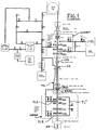
- the present invention gives instructions for an arrangement comprising a surface blowout preventer or BOP-stack which will form the main pressure control barrier, a high pressure riser pipe which is adapted for housing the drilling string, as well as a subsea blowout preventer adapted to disconnect the riser pipe system and secure the well at the sea bed, especially in connection with slim hole drilling.
- subsea blowout preventer stack should allow for pressure control through a separate high pressure circulation and test hose included in the control umbilical.
- connection must be designed, analyzed and tested by a third party other than wellhead equipment manufacturer.
- the accepted hub profile, gasket seal area and connector interface could then be given to the industry for standardization of the CTWH interface.
- the standard interface would be provided to wellhead suppliers, allowing standard interfaces to subsea connectors for the BOP stack.
- the CTBOP is lowered against the 9" wellhead until the bottom of the CTBOP is 5m above the wellhead.
- the weight of the submerged equipment is held in tension by the Snubbing Unit.
- Tube materials with a yield strength in the 85000 - 90000 psi minimum should be available. Special testing to ensure resistance to H2S cracking per NACE MR-0175 may be required.
- a stress joint also provides a transition from a rigid EQDP and Subsea CTBOP unit and the more flexible riser system. This serves to reduce the stress in the lower riser section and produce a stable bottom for the tensioned riser system.
- the riser connection shall be designed to be made up and torqued to an amount needed to ensure a preloaded connection. Interresting proven threaded connections such as API Spec. 7, Rotary Drilling Equipment, type threads are preferred.
- a swivel connection shall be used below the surface BOP's and above the upper riser termination. This will allow rotation of the CT vessel and CT surface equipment relative to the riser.
- the swivel shall rotate under all operational cases of the CT drilling system.
- Tubing injector head assembly The tubing injector head is designed to provide the thrust required, through a friction drive system, to snub the tubing into the well against pressure. It can also control the rate of lowering the tubing into the well if no well pressure exists, and pulling it out of the hole, to lift the full tubing weight and accelerate it to operating speed.
- the tubing reel assembly is a fabricated steel spool capable of handling up to 8.000 meter of coiled tubing.
- the inboard end of the tubing is connected through the hollow end of the reel shaft to a rotating joint, which is mounted to the reel shaft.
- the rotating joint stationary section is connected to the fluid or gas circulation pump system, thus circulation can be maintained continuously as the tubing is reeled on and retrieved from the well.
- a shutoff valve is provided between the tubing and the reel shaft for emergency use.
- a blowout preventor assembly is a device where the design provides positive protection against blowouts when operating coil tubing in well service work. BOPs can close around the tubing, close off an open hole, shear the tubing, grip and suspend the tubing, controlling the well pressure during all coiled tubing operations.
- the coiled tubing BOP assembly is a single bore Blowout Preventer Stack which will be attached directly to the high pressure riser and circulation line connections.
- the BOP assembly consists of three BOPs stacked in a single block.
- the BOPs are hydraulically operated with manual locking screw attachments.
- the rams can be positioned in any order from top to bottom.
- the Surface CTBOP must also allow for field replacement of the Seal/Grip Rams. Variable Seal Grip Rams to allow for both 3 1/2" DP and 2" CT is yet to be developed. The System must then be designed with two sets of ram blocks i.e. 2" CT and 3 1/2" DP
- the surface BOP to be used in conjunction with the subsea CTBOP will be: (from top to bottom)
- the surface BOPs will provide the normal well control during subsea coiled tubing drilling operations.
- control system for drilling with coiled tubing or small drill pipe
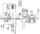
- the control system shall control both the surface BOP stack and assosiated equipment as well as the Subsea Coiled Tubing BOP with associated equipment. Since the most strignent requirement from rules and regulations conserns the subsea part of the system, this part will be the main guiding part of the study to choose type of control system. Bearing in mind that this control system shall be operated in 1500 meter of water, an electro hydraulic control system will be required. To cater for this it is recommended that a MULTIPLEXED control system is used.
- an electro hydraulic control system will be required to enable a common control system.
- the surface control system will also be manual operated.
- the control of the system will be through a Multiplex Surface Control Unit controlling the the Subsea Coiled Tubing BOP stack through a subsea multiplexed electrohydraulic system and the Surface Coiled Tubing BOP stack through an electrohydraulic control system.
- the surface BOP is manually controlled as well as controlled through the multiplexed control unit.
- the Control System shall contain the following main components:
- the two external control panels Connected to the main control panel are the two external control panels, one located on the rig flor, and one in the toolpushers office. These panels may operate all functions in the Well Pressure Control System and associated equipment controlled through the multiplex control system.
- the Electric supply skid consists of power supply for the Multiplex Surface Control unit and the surface control unit.
- a battery back-up with power supply is part of the skid.
- the Accumulator Skid cover the hydraulic accumulator capacity required for the well pressure control system explained by rules and regulations.
- the accumulator capacity cater for the complete well pressure control system, both subsea and surface.
- the accumulated volume shall be designed for 3.000 psi or 210 bar.
- the power unit consists of hydraulic pumps and associated equipment for the pumps such as starters, start and stop switches, gauges etc.
- the unit produces the hydraulic control fluid of 3.000 psi or 210 bar, and supplies both the subsea and surface systems via the accumulator skid.
- the unit utilizes water based control fluid which will be mixed by a mixing system on the unit.
- the mixing system should also allow for anti freeze mixture.
- the unit is based on hydraulically operated valves combined with manual operation for all functions.
- the functions can therefore be operated through the multiplexed system via solenoid valves which is electrically operated.
- the signal from the multiplex control system engages a solenoide which allows hydraulic pressure to switch the operating valve.
- the hydraulic pressure from the solenoide is kept as long as the push button on the control panel is pressed. When the button is released the pressure vents off.
- the correct working pressure for each function is controlled by hydraulic regulators which regulats the pressure down from 3.000 psi or 210 bar which is the maximum working pressure for the system. As several functions cater for the same working pressure it is estimated use of maximum 4 regulators.
- hydraulic fluid and electrical connection between the Multiplex Surface Control Unit and Subsea Control Module is required.
- the hydraulic control fluid is run through a hose from the hydraulic power unit to the Subsea Control Module. Normally both these functions are catered for in one hose with electric conduits enclosed in the hose.
- the Subsea Control Module only requires hydraulic fluid for the control POD and does not require any individual control lines.
- a special high pressure hose is required. This hose runs in parallel with the hydraulic control hose and the possibility to combine both in one common umbilical should be evaluated.
- One subsea electro-hydraulic control module shall be provided.
- the module shall contain all solenoids and operating valves, pressure transmitters, flowmeter etc as required for the operation of the Subsea CTBOP Assembly.
- the main operating principles shall be :
- Accumulators located on the CTBOP stack shall have sufficient capacity to enable:
- accumulators shall comply with NPD rules as a minimum.
- the same requirements for connections and hydraulic routing shall apply for the EQDP.
- the control valve for the EQDP Connector may be located on the EQDP or in the POD. This shall also apply to all control valves for the Riser Environmental Shut-off valve.
- the hydraulic control system operate and function on maximum working pressure of 3000 psi or 207 bar. All functions controlled from the control system and all components in the system shall comply with 207 bar as maximum working pressure.
- the surface control system controls following functions and components:
- the well head connector shall feature primary latch and unlatch.
- a secondary unlatch function shall be available in case of primary circuit failure.
- the secondary unlatch may be operational through the control system or operated by ROV only.
- an "open-to-sea" accumulator with corrosion inhibitor to prevent corrosion of the cylinders shall be present.
- the rams shall fail to closed position if pilot pressure is lost.
- the rams require return of exhaust fluid direct to sea without any common return line that can effect other rams or components.
- the rams shall have automatic locking device in closed position, in open position the rams are controlled by hydraulic opening pressure.
- the operating pressure for the rams is minimum 1500 psi (100 bar).
- the rams only require one pilot line for opening. This is part of the "Fail to close position" philosophy.
- valves have chambers or rooms that can be affected by the hydrostatic head, these shall be ventilated to special accumulators with corrosion inhibitors.
- the EQDC shall have the same configuration and be controlled similar to the well head connector.
- For emergency quick disconnects accumulators shall be installed to allow for a fast unlatch operation of the connector.
- the connector shall be fail as is and requires a positive pilot pressure for both opening and closing operation of the connector.
- the RESV has the same operational requirements as an annular preventer. It requires a separate easy adjustable hydraulic pressure for operations. This is achieved by a separate regulator for this function in the control POD.
- the control system shall cater for two modes,
- variable drill pipe rams are closed onto coiled tubing, no damage will occur.
- the SCDPSR will shear the coiled tubing, but this is allowed for and controlled by the control system.
- the SSCTSSR is only capable of shearing coiled tubing and component with smaller diameter. Accordingly a shear ram to allow for bigger sizes must be established which is the SCDPSR.
- Drill Pipe Mode will accordingly cater for following operation:
- an Emergency Quick Disconnect function is required.
- the function shall be sequence controlled by the control system and only involve the subsea CT BOP stack and EQDP. Due to the two modes, two different EQD commands are required.
- the SCDPSR will close after disconnect by itself. This is done in order to prevent a double cut of the coiled tubing, which may cause problems in a re-entry operation
- Step 1 SVDPR, Close All valves on the CTBOP stack, Close Riser Environm. Shut-off Valve, Close Well Head Connector: Vent.
- Step 2 SCDPSR, Close Step 3: Emergency Quick Disconnect Connector, Open
- the EQD function shall be available on the same locations as for the mode selection. To execute the EQD function only one button at each location shall be activated. The control system itself shall decide which sequence to be executed pending on which mode selected. One EQD button for each mode is not acceptable.
Landscapes
- Life Sciences & Earth Sciences (AREA)
- Engineering & Computer Science (AREA)
- Geology (AREA)
- Mining & Mineral Resources (AREA)
- Physics & Mathematics (AREA)
- Environmental & Geological Engineering (AREA)
- Fluid Mechanics (AREA)
- General Life Sciences & Earth Sciences (AREA)
- Geochemistry & Mineralogy (AREA)
- Earth Drilling (AREA)
Applications Claiming Priority (2)
| Application Number | Priority Date | Filing Date | Title |
|---|---|---|---|
| NO944136 | 1994-10-31 | ||
| NO19944136A NO305138B1 (no) | 1994-10-31 | 1994-10-31 | Anordning til bruk ved boring av olje/gass-bronner |
Publications (3)
| Publication Number | Publication Date |
|---|---|
| EP0709545A2 true EP0709545A2 (de) | 1996-05-01 |
| EP0709545A3 EP0709545A3 (de) | 1997-08-13 |
| EP0709545B1 EP0709545B1 (de) | 2003-01-15 |
Family
ID=19897576
Family Applications (1)
| Application Number | Title | Priority Date | Filing Date |
|---|---|---|---|
| EP95850188A Expired - Lifetime EP0709545B1 (de) | 1994-10-31 | 1995-10-31 | Dünnlochbohrsystem für tiefes Wasser |
Country Status (4)
| Country | Link |
|---|---|
| US (1) | US5727640A (de) |
| EP (1) | EP0709545B1 (de) |
| BR (1) | BR9505016A (de) |
| NO (1) | NO305138B1 (de) |
Cited By (12)
| Publication number | Priority date | Publication date | Assignee | Title |
|---|---|---|---|---|
| WO1999020872A1 (en) * | 1997-10-17 | 1999-04-29 | Timothy Mark Overfield | Novel control system |
| WO2002055836A1 (en) * | 2001-01-10 | 2002-07-18 | 2H Offshore Engineering Ltd. | Method of drilling and operating a subsea well |
| WO2002088516A1 (en) * | 2001-04-30 | 2002-11-07 | Shell Internationale Research Maatschappij B.V. | Subsea drilling riser disconnect system and method |
| WO2005005770A1 (en) * | 2003-06-20 | 2005-01-20 | Shell Oil Company | Systems and methods for constructing subsea production wells |
| WO2006010906A1 (en) * | 2004-07-24 | 2006-02-02 | Bamford Anthony S | Improvements in or relating to subsea drilling |
| SG134999A1 (en) * | 2002-11-26 | 2007-09-28 | Cooper Cameron Corp | Subsea connection apparatus for a surface blowout preventer stack |
| US8590634B2 (en) | 2004-07-24 | 2013-11-26 | Geoprober Drilling Limited | Subsea drilling |
| CN104832091A (zh) * | 2015-02-24 | 2015-08-12 | 侯绪田 | 一种深水sbop钻井系统 |
| EP2281103A4 (de) * | 2008-04-04 | 2015-09-02 | Ocean Riser Systems As | System und verfahren für unterwasserbohrungen |
| WO2016203248A1 (en) * | 2015-06-17 | 2016-12-22 | Enovate Systems Limited | Improved pressure barrier system |
| US9970255B2 (en) | 2016-02-02 | 2018-05-15 | Trendsetter Engineering, Inc. | Relief well injection spool apparatus and method for killing a blowing well |
| US20210180418A1 (en) * | 2019-12-12 | 2021-06-17 | Halliburton Energy Services, Inc. | Prospective kick loss detection for off-shore drilling |
Families Citing this family (29)
| Publication number | Priority date | Publication date | Assignee | Title |
|---|---|---|---|---|
| US6273193B1 (en) | 1997-12-16 | 2001-08-14 | Transocean Sedco Forex, Inc. | Dynamically positioned, concentric riser, drilling method and apparatus |
| WO2000008295A1 (en) * | 1998-08-03 | 2000-02-17 | Deep Vision Llc | An apparatus and method for killing a subsea well |
| EP1103459A1 (de) | 1999-11-24 | 2001-05-30 | Mercur Slimhole Drilling and Intervention AS | Anordnung zum Ausgleich von Tauch- und Tidebewegungen |
| US6343893B1 (en) | 1999-11-29 | 2002-02-05 | Mercur Slimhole Drilling And Intervention As | Arrangement for controlling floating drilling and intervention vessels |
| GB9930450D0 (en) * | 1999-12-23 | 2000-02-16 | Eboroil Sa | Subsea well intervention vessel |
| USRE43199E1 (en) * | 2001-09-10 | 2012-02-21 | Ocean Rider Systems AS | Arrangement and method for regulating bottom hole pressures when drilling deepwater offshore wells |
| CA2461639C (en) | 2001-09-10 | 2013-08-06 | Ocean Riser Systems As | Arrangement and method for regulating bottom hole pressures when drilling deepwater offshore wells |
| US6834721B2 (en) * | 2002-01-14 | 2004-12-28 | Halliburton Energy Services, Inc. | System for disconnecting coiled tubing |
| NO316183B1 (no) * | 2002-03-08 | 2003-12-22 | Sigbjoern Sangesland | Fremgangsmåte og anordning ved fôringsrör |
| US7395866B2 (en) * | 2002-09-13 | 2008-07-08 | Dril-Quip, Inc. | Method and apparatus for blow-out prevention in subsea drilling/completion systems |
| US7434624B2 (en) * | 2002-10-03 | 2008-10-14 | Exxonmobil Upstream Research Company | Hybrid tension-leg riser |
| US7950463B2 (en) | 2003-03-13 | 2011-05-31 | Ocean Riser Systems As | Method and arrangement for removing soils, particles or fluids from the seabed or from great sea depths |
| NO318220B1 (no) | 2003-03-13 | 2005-02-21 | Ocean Riser Systems As | Fremgangsmåte og anordning for utførelse av boreoperasjoner |
| US7032691B2 (en) * | 2003-10-30 | 2006-04-25 | Stena Drilling Ltd. | Underbalanced well drilling and production |
| US7021402B2 (en) * | 2003-12-15 | 2006-04-04 | Itrec B.V. | Method for using a multipurpose unit with multipurpose tower and a surface blow out preventer |
| US20060162933A1 (en) * | 2004-09-01 | 2006-07-27 | Millheim Keith K | System and method of installing and maintaining an offshore exploration and production system having an adjustable buoyancy chamber |
| US7458425B2 (en) * | 2004-09-01 | 2008-12-02 | Anadarko Petroleum Corporation | System and method of installing and maintaining an offshore exploration and production system having an adjustable buoyancy chamber |
| US7296628B2 (en) | 2004-11-30 | 2007-11-20 | Mako Rentals, Inc. | Downhole swivel apparatus and method |
| US8579033B1 (en) | 2006-05-08 | 2013-11-12 | Mako Rentals, Inc. | Rotating and reciprocating swivel apparatus and method with threaded end caps |
| DK2016254T3 (en) | 2006-05-08 | 2017-07-10 | Mako Rentals Inc | APPARATUS AND PROCEDURE FOR BIRTHLINE TO DRILL |
| CN101730782B (zh) * | 2007-06-01 | 2014-10-22 | Agr深水发展系统股份有限公司 | 双密度泥浆返回系统 |
| DK2176503T3 (en) | 2007-08-06 | 2018-01-22 | Mako Rentals Inc | Rotating and reciprocating rotary joint device and method |
| US7938190B2 (en) * | 2007-11-02 | 2011-05-10 | Agr Subsea, Inc. | Anchored riserless mud return systems |
| US8746345B2 (en) * | 2010-12-09 | 2014-06-10 | Cameron International Corporation | BOP stack with a universal intervention interface |
| US10060207B2 (en) * | 2011-10-05 | 2018-08-28 | Helix Energy Solutions Group, Inc. | Riser system and method of use |
| US9260931B2 (en) | 2013-03-11 | 2016-02-16 | Bp Corporation North America Inc. | Riser breakaway connection and intervention coupling device |
| US9951577B2 (en) * | 2014-12-15 | 2018-04-24 | Barry McMiles | Emergency wellbore intervention system |
| US11319769B2 (en) * | 2020-04-30 | 2022-05-03 | Saudi Arabian Oil Company | Multi-intervention blowout preventer and methods of use thereof |
| US12163396B2 (en) * | 2022-10-21 | 2024-12-10 | Chevron U.S.A. Inc. | Systems and methods for independent control and operations of tubing and annulus at the wellhead |
Citations (2)
| Publication number | Priority date | Publication date | Assignee | Title |
|---|---|---|---|---|
| US3424253A (en) | 1956-12-03 | 1969-01-28 | Chevron Res | Method for drilling and working in offshore wells |
| US4046191A (en) | 1975-07-07 | 1977-09-06 | Exxon Production Research Company | Subsea hydraulic choke |
Family Cites Families (10)
| Publication number | Priority date | Publication date | Assignee | Title |
|---|---|---|---|---|
| US3179179A (en) * | 1961-10-16 | 1965-04-20 | Richfield Oil Corp | Off-shore drilling apparatus |
| US3603409A (en) * | 1969-03-27 | 1971-09-07 | Regan Forge & Eng Co | Method and apparatus for balancing subsea internal and external well pressures |
| US3825065A (en) * | 1972-12-05 | 1974-07-23 | Exxon Production Research Co | Method and apparatus for drilling in deep water |
| US3913668A (en) * | 1973-08-22 | 1975-10-21 | Exxon Production Research Co | Marine riser assembly |
| US4193455A (en) * | 1978-04-14 | 1980-03-18 | Chevron Research Company | Split stack blowout prevention system |
| US4291772A (en) * | 1980-03-25 | 1981-09-29 | Standard Oil Company (Indiana) | Drilling fluid bypass for marine riser |
| US4557332A (en) * | 1984-04-09 | 1985-12-10 | Shell Offshore Inc. | Drilling riser locking apparatus and method |
| US4632188A (en) * | 1985-09-04 | 1986-12-30 | Atlantic Richfield Company | Subsea wellhead apparatus |
| US5199683A (en) * | 1992-06-09 | 1993-04-06 | Baroid Technology, Inc. | Blowout preventer opening mechanism |
| WO1995017576A1 (en) * | 1993-12-20 | 1995-06-29 | Shell Internationale Research Maatschappij B.V. | Dual concentric string high pressure riser |
-
1994
- 1994-10-31 NO NO19944136A patent/NO305138B1/no not_active IP Right Cessation
-
1995
- 1995-10-30 US US08/550,495 patent/US5727640A/en not_active Expired - Lifetime
- 1995-10-30 BR BR9505016A patent/BR9505016A/pt not_active IP Right Cessation
- 1995-10-31 EP EP95850188A patent/EP0709545B1/de not_active Expired - Lifetime
Patent Citations (2)
| Publication number | Priority date | Publication date | Assignee | Title |
|---|---|---|---|---|
| US3424253A (en) | 1956-12-03 | 1969-01-28 | Chevron Res | Method for drilling and working in offshore wells |
| US4046191A (en) | 1975-07-07 | 1977-09-06 | Exxon Production Research Company | Subsea hydraulic choke |
Cited By (20)
| Publication number | Priority date | Publication date | Assignee | Title |
|---|---|---|---|---|
| WO1999020872A1 (en) * | 1997-10-17 | 1999-04-29 | Timothy Mark Overfield | Novel control system |
| WO2002055836A1 (en) * | 2001-01-10 | 2002-07-18 | 2H Offshore Engineering Ltd. | Method of drilling and operating a subsea well |
| US7073593B2 (en) | 2001-01-10 | 2006-07-11 | 2H Offshore Engineering Ltd | Method of drilling and operating a subsea well |
| WO2002088516A1 (en) * | 2001-04-30 | 2002-11-07 | Shell Internationale Research Maatschappij B.V. | Subsea drilling riser disconnect system and method |
| GB2391889A (en) * | 2001-04-30 | 2004-02-18 | Shell Int Research | Subsea drilling riser disconnect system and method |
| US9085951B2 (en) | 2002-11-26 | 2015-07-21 | Cameron International Corporation | Subsea connection apparatus for a surface blowout preventer stack |
| SG134999A1 (en) * | 2002-11-26 | 2007-09-28 | Cooper Cameron Corp | Subsea connection apparatus for a surface blowout preventer stack |
| US8695691B2 (en) | 2002-11-26 | 2014-04-15 | Cameron International Corporation | Subsea connection apparatus for a surface blowout preventer stack |
| US8136598B2 (en) | 2002-11-26 | 2012-03-20 | Cameron International Corporation | Subsea connection apparatus for a surface blowout preventer stack |
| WO2005005770A1 (en) * | 2003-06-20 | 2005-01-20 | Shell Oil Company | Systems and methods for constructing subsea production wells |
| US8590634B2 (en) | 2004-07-24 | 2013-11-26 | Geoprober Drilling Limited | Subsea drilling |
| US7819204B2 (en) | 2004-07-24 | 2010-10-26 | Geoprober Drilling Limited | Subsea drilling |
| WO2006010906A1 (en) * | 2004-07-24 | 2006-02-02 | Bamford Anthony S | Improvements in or relating to subsea drilling |
| EP2281103A4 (de) * | 2008-04-04 | 2015-09-02 | Ocean Riser Systems As | System und verfahren für unterwasserbohrungen |
| US9222311B2 (en) | 2008-04-04 | 2015-12-29 | Ocean Riser Systems AS Lilleakerveien 2B | Systems and methods for subsea drilling |
| CN104832091A (zh) * | 2015-02-24 | 2015-08-12 | 侯绪田 | 一种深水sbop钻井系统 |
| WO2016203248A1 (en) * | 2015-06-17 | 2016-12-22 | Enovate Systems Limited | Improved pressure barrier system |
| US9970255B2 (en) | 2016-02-02 | 2018-05-15 | Trendsetter Engineering, Inc. | Relief well injection spool apparatus and method for killing a blowing well |
| US10280716B2 (en) | 2016-02-02 | 2019-05-07 | Trendsetter Engineering, Inc. | Process and system for killing a well through the use of relief well injection spools |
| US20210180418A1 (en) * | 2019-12-12 | 2021-06-17 | Halliburton Energy Services, Inc. | Prospective kick loss detection for off-shore drilling |
Also Published As
| Publication number | Publication date |
|---|---|
| NO944136L (no) | 1996-05-02 |
| NO944136D0 (no) | 1994-10-31 |
| EP0709545B1 (de) | 2003-01-15 |
| EP0709545A3 (de) | 1997-08-13 |
| NO305138B1 (no) | 1999-04-06 |
| BR9505016A (pt) | 1997-10-14 |
| US5727640A (en) | 1998-03-17 |
Similar Documents
| Publication | Publication Date | Title |
|---|---|---|
| EP0709545B1 (de) | Dünnlochbohrsystem für tiefes Wasser | |
| US7318480B2 (en) | Tubing running equipment for offshore rig with surface blowout preventer | |
| US9297214B2 (en) | Marine subsea free-standing riser systems and methods | |
| US8297359B2 (en) | Subsea well intervention systems and methods | |
| RU2579062C2 (ru) | Способ и система локализации неуправляемого потока текучих сред коллектора в окружающую среду | |
| US8695691B2 (en) | Subsea connection apparatus for a surface blowout preventer stack | |
| EP1350003B1 (de) | Verfahren zum bohren und zum betrieb eines unterwasserbohrlochs | |
| US6173781B1 (en) | Slip joint intervention riser with pressure seals and method of using the same | |
| US4630680A (en) | Well control method and apparatus | |
| US20120111572A1 (en) | Emergency control system for subsea blowout preventer | |
| US9574426B2 (en) | Offshore well system with a subsea pressure control system movable with a remotely operated vehicle | |
| US9353602B2 (en) | Riser weak link | |
| US8826989B2 (en) | Method for capping a well in the event of subsea blowout preventer failure | |
| NO20140567A1 (no) | BOP sammenstilling for nødavstengning | |
| US9038728B1 (en) | System and method for diverting fluids from a wellhead by using a modified horizontal christmas tree | |
| US11414949B2 (en) | Deepwater riser intervention system | |
| EP3414421A1 (de) | Vorrichtung und verfahren zur ermöglichung der entfernung oder aufstellung eines horizontalen weihnachtsbaums | |
| KR20150003191U (ko) | Bop 백업 제어 시스템 및 이를 포함하는 bop 시스템 | |
| GB1590387A (en) | Apparatus and method for conducting deep water well operations | |
| Harris | Floating Drilling Experience in Santa Barbara Channel, California | |
| Harris | Design for Reliability in Floating Drilling Operations | |
| Gillette et al. | Subsea Trees and Controls for Australian Bass Strait Development | |
| Parks et al. | Deepwater completion/workover riser and control system |
Legal Events
| Date | Code | Title | Description |
|---|---|---|---|
| PUAI | Public reference made under article 153(3) epc to a published international application that has entered the european phase |
Free format text: ORIGINAL CODE: 0009012 |
|
| AK | Designated contracting states |
Kind code of ref document: A2 Designated state(s): DK ES FR GB GR IT NL |
|
| PUAL | Search report despatched |
Free format text: ORIGINAL CODE: 0009013 |
|
| AK | Designated contracting states |
Kind code of ref document: A3 Designated state(s): DK ES FR GB GR IT NL |
|
| 17P | Request for examination filed |
Effective date: 19971103 |
|
| RAP1 | Party data changed (applicant data changed or rights of an application transferred) |
Owner name: MERCUR SLIMHOLE DRILLING AND INTERVENTION AS |
|
| 17Q | First examination report despatched |
Effective date: 20010129 |
|
| GRAG | Despatch of communication of intention to grant |
Free format text: ORIGINAL CODE: EPIDOS AGRA |
|
| GRAG | Despatch of communication of intention to grant |
Free format text: ORIGINAL CODE: EPIDOS AGRA |
|
| GRAH | Despatch of communication of intention to grant a patent |
Free format text: ORIGINAL CODE: EPIDOS IGRA |
|
| GRAH | Despatch of communication of intention to grant a patent |
Free format text: ORIGINAL CODE: EPIDOS IGRA |
|
| GRAA | (expected) grant |
Free format text: ORIGINAL CODE: 0009210 |
|
| AK | Designated contracting states |
Kind code of ref document: B1 Designated state(s): DK ES FR GB GR IT NL |
|
| PG25 | Lapsed in a contracting state [announced via postgrant information from national office to epo] |
Ref country code: NL Free format text: LAPSE BECAUSE OF FAILURE TO SUBMIT A TRANSLATION OF THE DESCRIPTION OR TO PAY THE FEE WITHIN THE PRESCRIBED TIME-LIMIT Effective date: 20030115 Ref country code: IT Free format text: LAPSE BECAUSE OF FAILURE TO SUBMIT A TRANSLATION OF THE DESCRIPTION OR TO PAY THE FEE WITHIN THE PRE;WARNING: LAPSES OF ITALIAN PATENTS WITH EFFECTIVE DATE BEFORE 2007 MAY HAVE OCCURRED AT ANY TIME BEFORE 2007. THE CORRECT EFFECTIVE DATE MAY BE DIFFERENT FROM THE ONE RECORDED.SCRIBED TIME-LIMIT Effective date: 20030115 Ref country code: GR Free format text: LAPSE BECAUSE OF FAILURE TO SUBMIT A TRANSLATION OF THE DESCRIPTION OR TO PAY THE FEE WITHIN THE PRESCRIBED TIME-LIMIT Effective date: 20030115 Ref country code: FR Free format text: LAPSE BECAUSE OF NON-PAYMENT OF DUE FEES Effective date: 20030115 |
|
| REG | Reference to a national code |
Ref country code: GB Ref legal event code: FG4D |
|
| PG25 | Lapsed in a contracting state [announced via postgrant information from national office to epo] |
Ref country code: DK Free format text: LAPSE BECAUSE OF FAILURE TO SUBMIT A TRANSLATION OF THE DESCRIPTION OR TO PAY THE FEE WITHIN THE PRESCRIBED TIME-LIMIT Effective date: 20030415 |
|
| NLV1 | Nl: lapsed or annulled due to failure to fulfill the requirements of art. 29p and 29m of the patents act | ||
| PG25 | Lapsed in a contracting state [announced via postgrant information from national office to epo] |
Ref country code: ES Free format text: LAPSE BECAUSE OF FAILURE TO SUBMIT A TRANSLATION OF THE DESCRIPTION OR TO PAY THE FEE WITHIN THE PRESCRIBED TIME-LIMIT Effective date: 20030730 |
|
| PLBE | No opposition filed within time limit |
Free format text: ORIGINAL CODE: 0009261 |
|
| STAA | Information on the status of an ep patent application or granted ep patent |
Free format text: STATUS: NO OPPOSITION FILED WITHIN TIME LIMIT |
|
| EN | Fr: translation not filed | ||
| 26N | No opposition filed |
Effective date: 20031016 |
|
| PGFP | Annual fee paid to national office [announced via postgrant information from national office to epo] |
Ref country code: GB Payment date: 20141027 Year of fee payment: 20 |
|
| REG | Reference to a national code |
Ref country code: GB Ref legal event code: PE20 Expiry date: 20151030 |
|
| PG25 | Lapsed in a contracting state [announced via postgrant information from national office to epo] |
Ref country code: GB Free format text: LAPSE BECAUSE OF EXPIRATION OF PROTECTION Effective date: 20151030 |