EP0709577B1 - Ventil mit vier Verbindungsöffnungen und zwei Stellungen - Google Patents
Ventil mit vier Verbindungsöffnungen und zwei Stellungen Download PDFInfo
- Publication number
- EP0709577B1 EP0709577B1 EP19950440070 EP95440070A EP0709577B1 EP 0709577 B1 EP0709577 B1 EP 0709577B1 EP 19950440070 EP19950440070 EP 19950440070 EP 95440070 A EP95440070 A EP 95440070A EP 0709577 B1 EP0709577 B1 EP 0709577B1
- Authority
- EP
- European Patent Office
- Prior art keywords
- port
- orifice
- valve
- connection
- return valve
- Prior art date
- Legal status (The legal status is an assumption and is not a legal conclusion. Google has not performed a legal analysis and makes no representation as to the accuracy of the status listed.)
- Expired - Lifetime
Links
- 239000012530 fluid Substances 0.000 claims description 26
- 210000000056 organ Anatomy 0.000 description 6
- 238000006073 displacement reaction Methods 0.000 description 3
- 238000006386 neutralization reaction Methods 0.000 description 1
Images

Classifications
-
- F—MECHANICAL ENGINEERING; LIGHTING; HEATING; WEAPONS; BLASTING
- F15—FLUID-PRESSURE ACTUATORS; HYDRAULICS OR PNEUMATICS IN GENERAL
- F15B—SYSTEMS ACTING BY MEANS OF FLUIDS IN GENERAL; FLUID-PRESSURE ACTUATORS, e.g. SERVOMOTORS; DETAILS OF FLUID-PRESSURE SYSTEMS, NOT OTHERWISE PROVIDED FOR
- F15B11/00—Servomotor systems without provision for follow-up action; Circuits therefor
- F15B11/02—Systems essentially incorporating special features for controlling the speed or actuating force of an output member
- F15B11/024—Systems essentially incorporating special features for controlling the speed or actuating force of an output member by means of differential connection of the servomotor lines, e.g. regenerative circuits
-
- F—MECHANICAL ENGINEERING; LIGHTING; HEATING; WEAPONS; BLASTING
- F15—FLUID-PRESSURE ACTUATORS; HYDRAULICS OR PNEUMATICS IN GENERAL
- F15B—SYSTEMS ACTING BY MEANS OF FLUIDS IN GENERAL; FLUID-PRESSURE ACTUATORS, e.g. SERVOMOTORS; DETAILS OF FLUID-PRESSURE SYSTEMS, NOT OTHERWISE PROVIDED FOR
- F15B2211/00—Circuits for servomotor systems
- F15B2211/30—Directional control
- F15B2211/305—Directional control characterised by the type of valves
- F15B2211/30505—Non-return valves, i.e. check valves
-
- F—MECHANICAL ENGINEERING; LIGHTING; HEATING; WEAPONS; BLASTING
- F15—FLUID-PRESSURE ACTUATORS; HYDRAULICS OR PNEUMATICS IN GENERAL
- F15B—SYSTEMS ACTING BY MEANS OF FLUIDS IN GENERAL; FLUID-PRESSURE ACTUATORS, e.g. SERVOMOTORS; DETAILS OF FLUID-PRESSURE SYSTEMS, NOT OTHERWISE PROVIDED FOR
- F15B2211/00—Circuits for servomotor systems
- F15B2211/30—Directional control
- F15B2211/305—Directional control characterised by the type of valves
- F15B2211/30525—Directional control valves, e.g. 4/3-directional control valve
-
- F—MECHANICAL ENGINEERING; LIGHTING; HEATING; WEAPONS; BLASTING
- F15—FLUID-PRESSURE ACTUATORS; HYDRAULICS OR PNEUMATICS IN GENERAL
- F15B—SYSTEMS ACTING BY MEANS OF FLUIDS IN GENERAL; FLUID-PRESSURE ACTUATORS, e.g. SERVOMOTORS; DETAILS OF FLUID-PRESSURE SYSTEMS, NOT OTHERWISE PROVIDED FOR
- F15B2211/00—Circuits for servomotor systems
- F15B2211/30—Directional control
- F15B2211/31—Directional control characterised by the positions of the valve element
- F15B2211/3122—Special positions other than the pump port being connected to working ports or the working ports being connected to the return line
- F15B2211/3127—Floating position connecting the working ports and the return line
-
- F—MECHANICAL ENGINEERING; LIGHTING; HEATING; WEAPONS; BLASTING
- F15—FLUID-PRESSURE ACTUATORS; HYDRAULICS OR PNEUMATICS IN GENERAL
- F15B—SYSTEMS ACTING BY MEANS OF FLUIDS IN GENERAL; FLUID-PRESSURE ACTUATORS, e.g. SERVOMOTORS; DETAILS OF FLUID-PRESSURE SYSTEMS, NOT OTHERWISE PROVIDED FOR
- F15B2211/00—Circuits for servomotor systems
- F15B2211/30—Directional control
- F15B2211/315—Directional control characterised by the connections of the valve or valves in the circuit
- F15B2211/3157—Directional control characterised by the connections of the valve or valves in the circuit being connected to a pressure source, an output member and a return line
- F15B2211/31576—Directional control characterised by the connections of the valve or valves in the circuit being connected to a pressure source, an output member and a return line having a single pressure source and a single output member
-
- F—MECHANICAL ENGINEERING; LIGHTING; HEATING; WEAPONS; BLASTING
- F15—FLUID-PRESSURE ACTUATORS; HYDRAULICS OR PNEUMATICS IN GENERAL
- F15B—SYSTEMS ACTING BY MEANS OF FLUIDS IN GENERAL; FLUID-PRESSURE ACTUATORS, e.g. SERVOMOTORS; DETAILS OF FLUID-PRESSURE SYSTEMS, NOT OTHERWISE PROVIDED FOR
- F15B2211/00—Circuits for servomotor systems
- F15B2211/30—Directional control
- F15B2211/32—Directional control characterised by the type of actuation
- F15B2211/329—Directional control characterised by the type of actuation actuated by fluid pressure
-
- F—MECHANICAL ENGINEERING; LIGHTING; HEATING; WEAPONS; BLASTING
- F15—FLUID-PRESSURE ACTUATORS; HYDRAULICS OR PNEUMATICS IN GENERAL
- F15B—SYSTEMS ACTING BY MEANS OF FLUIDS IN GENERAL; FLUID-PRESSURE ACTUATORS, e.g. SERVOMOTORS; DETAILS OF FLUID-PRESSURE SYSTEMS, NOT OTHERWISE PROVIDED FOR
- F15B2211/00—Circuits for servomotor systems
- F15B2211/70—Output members, e.g. hydraulic motors or cylinders or control therefor
- F15B2211/705—Output members, e.g. hydraulic motors or cylinders or control therefor characterised by the type of output members or actuators
- F15B2211/7051—Linear output members
- F15B2211/7053—Double-acting output members
- F15B2211/7054—Having equal piston areas
-
- Y—GENERAL TAGGING OF NEW TECHNOLOGICAL DEVELOPMENTS; GENERAL TAGGING OF CROSS-SECTIONAL TECHNOLOGIES SPANNING OVER SEVERAL SECTIONS OF THE IPC; TECHNICAL SUBJECTS COVERED BY FORMER USPC CROSS-REFERENCE ART COLLECTIONS [XRACs] AND DIGESTS
- Y10—TECHNICAL SUBJECTS COVERED BY FORMER USPC
- Y10T—TECHNICAL SUBJECTS COVERED BY FORMER US CLASSIFICATION
- Y10T137/00—Fluid handling
- Y10T137/2496—Self-proportioning or correlating systems
- Y10T137/2544—Supply and exhaust type
- Y10T137/2554—Reversing or 4-way valve systems
Definitions
- the present invention relates to a valve with four connection orifices and two positions intended, in one of its positions, to supply at least one organ to animate and, in the other position, to put in communication at least two chambers of said organ (s), the pressure therein being low or even almost zero, regardless of the main circuit operating pressure or the pressure directly supplied by the fluid supply source.
- valve according to the invention When the valve according to the invention is in the first position, it is therefore possible to supply the organ (s) with a certain pressure, then to maintain this pressure thanks to the first non-return valve.
- a third non-return valve allowing only the circulation of the fluid of the second port to the second connection port.
- This third valve of non-return thus isolates the organ (s) from any pressure build-up which may appear at the second connection orifice when the valve (or more exactly the distributor of this one) is in the first position.
- At least one non-return valves may be of the "spring loaded” type.
- Preferably to minus the second non-return valve will be of the "spring loaded” type.
- the two the dispenser positions may advantageously be lockable by means of a locking device.
- this locking device will be a mechanical locking device.
- provision may be made for the locking of the two positions is done automatically. It may also be provided that the unlocking of said positions is done automatically.
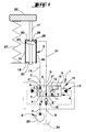
- the valve (1) according to the invention shown schematically in Figures 1 and 2, has four connection holes (A, B, C, D).
- the first opening of connection (A) and the second connection orifice (B) are connected to a fluid supply source (2).
- the third port (C) and the fourth port (D), for their part, are connected to a member (3) to be animated.
- the valve (1) also comprises a distributor (4) with four orifices (A ', B ', C', D ') and two positions (5, 6).
- the first opening (A ') is directly in communication with the first connection orifice (A).
- the third opening (C ') is directly in communication with the third connection orifice (VS).
- the fourth opening (D ') is in direct communication with the fourth connection orifice (D).
- the distributor (4) has two channels (7, 8).
- the first channel (7) which allows the first port to be put into communication (A ') and the third orifice (C'), includes a non-return valve (9) allowing only the circulation of the fluid from the first port (A ') to the third port (VS').
- This first non-return valve (9) is a non-return valve of the type "with spring ".
- the second channel (8) for its part, allows the free circulation of the fluid between the second orifice (B ') and the fourth orifice (D').
- the distributor (4) has two other channels: a third channel (10) which puts the third orifice (C ') directly in communication with the fourth orifice (D ') so that the fluid can circulate freely between these two orifices (C 'and D'), and a fourth channel (11) allowing to put the first port (A ') and the third channel (10) into communication.
- This fourth channel (11) has a second non-return valve (12) allowing only the circulation of the fluid from the third channel (10) to the first orifice (AT').
- This second non-return valve (12) is also a non-return valve. of the "with spring" type.
- the second opening (B ') is closed in the second position (6).
- the valve (1) also includes a third non-return valve (15) implanted between the second connection orifice (B) and the second orifice (B ').
- This valve non-return (15) only allows the circulation of the fluid of the second orifice (B ') to the second connection orifice (B).
- This third valve of non-return valve (15) is also a non-return valve of the "with spring" type.
- this valve (1) will appear clearly in the following description of an example of use with a double rod cylinder (16) (17).
- the first chamber (18) of this jack (16) is connected to the third connection orifice (C) by a first pipe (19), while the second chamber (20) of said cylinder (16) is connected to the fourth connection orifice (D) by a second line (21).
- the pressure supplied by the pump (23) at the first connection orifice (A) automatically deactivates the locking device (14), then the control by the control device (13) of the placing of the distributor (4) in its first position (5).
- the locking device (14) again automatically locks the dispenser (4) in this new position.
- the fluid delivered by the pump (23) opens the first non-return valve (9), circulates in the first pipe (19) and enters in the first chamber (18) of the jack (16). In doing so, this fluid repels the rod (17)-piston (25) assembly in the cylinder (26) to lift the mass (22).
- the piston (25) expels the fluid contained in the second chamber (20) of the jack (16), which fluid circulates in the second pipe (21) and the second way (8), opens the third non-return valve (15) and flows into the reservoir (24) of the fluid supply source (2).
- the pressure prevailing in the first chamber (18) of the jack (16) is held by the first non-return valve (9).
- the third non-return valve (15) isolates the second chamber (20) of the jack (16) of any pressure build-up which can appear at the second connection orifice (B).
- valve (1) which has just been described, may be devoid of the third non-return valve (15) when, in the first position (5), it it is not necessary to isolate the second chamber (20) of the jack (16) from any pressure build-up which may appear at the second connection orifice (B).
- valve of the invention can be used in other applications than the one just described (hydraulic or pneumatic).
- the calibration value of the non-return valves (9, 12 and 15) depends on the use of the valve. A whole range of valves can thus be created with different taring values.
- the second non-return valve (12) will be a valve. non-return with spring.
- first connection orifice (A) and / or the third connection port (C) and / or the fourth connection orifice (D) will be (will) be confused with the first port (A ') and / or the third port (C') and / or the fourth port (D ').
- the control device (13) can be of any configuration since it allows the distributor (4) to be put in its first position (5) and in its second position (6).
- the locking device (14) may also be of a configuration any where it allows the distributor (4) to be locked in each of its two positions (5 and 6).
Landscapes
- Engineering & Computer Science (AREA)
- Physics & Mathematics (AREA)
- Fluid Mechanics (AREA)
- Mechanical Engineering (AREA)
- General Engineering & Computer Science (AREA)
- Multiple-Way Valves (AREA)
- Lift Valve (AREA)
- Fluid-Pressure Circuits (AREA)
- Servomotors (AREA)
Claims (6)
- Ventil (1) mit:a) vier Verbindungsöffnungen (A, B, C, D), von denen eine erste Verbindungsöffnung (A) und eine zweite Verbindungsöffnung (B) zur direkten oder indirekten Verbindung mit einer Fluidversorgungsquelle (2) bestimmt sind und von denen eine dritte Verbindungsöffnung (C) und eine vierte Verbindungsöffnung (D) zur direkten oder indirekten Verbindung mit einem oder mehreren zu betätigenden Elementen (3) bestimmt sind;b) einem Verteiler (4):mit vier Öffnungen (A', B', C', D'), von denen eine erste Öffnung (A'), eine dritte Öffnung (C') und eine vierte Öffnung (D') mit der ersten Verbindungsöffnung (A), der dritten Verbindungsöffnung (C) bzw. der vierten Verbindungsöffnung (D) direkt in Verbindung stehen oder damit zusammenfallen; undmit zwei Stellungen (5, 6) die mittels einer Steuervorrichtung (13) in Betriebsbereitschaft gesetzt werden können:einer ersten Stellung (5), in der eine erste Rückschlagklappe (9) nur den Umlauf des Fluids von der ersten Öffnung (A') zur dritten Öffnung (C') gestattet, während eine zweite Öffnung (B') und die vierte Öffnung (D') direkt miteinander in Verbindung stehen,einer zweiten Stellung (6), in der die dritte Öffnung (C') und die vierte Öffnung (D') direkt miteinander in Verbindung stehen, während eine zweite Rückschlagklappe (12) nur den Umlauf von Fluid von der in Verbindung stehenden dritten (C') und vierten Öffnungen (D') zur ersten Öffnung (A') gestattet.
- Ventil nach Anspruch 1, dadurch gekennzeichnet, daß es eine dritte Rückschlagklappe (15) enthält, die nur den Umlauf des Fluids von der zweiten Öffnung (B') zur zweiten Verbindungsöffnung (B) gestattet.
- Ventil nach Anspruch 1 oder 2, dadurch gekennzeichnet, daß mindestens eine der Rückschlagklappen (9, 12, 15) eine federbelastete Rückschlagklappe ist.
- Ventil nach Anspruch 3, dadurch gekennzeichnet, daß zumindest die zweite Rückschlagklappe (12) eine federbelastete Rückschlagklappe ist.
- Ventil nach irgend einem der Ansprüche 1 bis 4, dadurch gekennzeichnet, daß die beiden Stellungen (5, 6) des Verteilers (4) mittels einer Verriegelungsvorrichtung (14) verriegelbar sind.
- Ventil nach irgend einem der Ansprüche 1 bis 5, dadurch gekennzeichnet, daß die Steuervorrichtung (13) das Positionieren des Verteilers (4)steuert.in die erste Stellung (5) von dem an der ersten Verbindungsöffnung (A) herrschenden Druck undin die zweite Stellung (6) von dem an der zweiten Verbindungsöffnung (B) herrschenden Druck
Applications Claiming Priority (2)
| Application Number | Priority Date | Filing Date | Title |
|---|---|---|---|
| FR9413107A FR2726343B1 (fr) | 1994-10-28 | 1994-10-28 | Valve a quatre orifices de raccordement et deux positions |
| FR9413107 | 1994-10-28 |
Publications (2)
| Publication Number | Publication Date |
|---|---|
| EP0709577A1 EP0709577A1 (de) | 1996-05-01 |
| EP0709577B1 true EP0709577B1 (de) | 2000-06-07 |
Family
ID=9468447
Family Applications (1)
| Application Number | Title | Priority Date | Filing Date |
|---|---|---|---|
| EP19950440070 Expired - Lifetime EP0709577B1 (de) | 1994-10-28 | 1995-10-26 | Ventil mit vier Verbindungsöffnungen und zwei Stellungen |
Country Status (5)
| Country | Link |
|---|---|
| US (1) | US5749390A (de) |
| EP (1) | EP0709577B1 (de) |
| JP (1) | JPH08210308A (de) |
| DE (1) | DE69517386T2 (de) |
| FR (1) | FR2726343B1 (de) |
Families Citing this family (17)
| Publication number | Priority date | Publication date | Assignee | Title |
|---|---|---|---|---|
| FR2784003B1 (fr) | 1998-10-02 | 2000-12-29 | Kuhn Sa | Machine agricole comportant un timon pivotable et des organes de transmission comprenant un accouplement a joints universels |
| FR2786977B1 (fr) | 1998-12-14 | 2001-02-16 | Kuhn Sa | Faucheuse comportant un dispositif centralise de reglage de la force d'allegement exercee sur le mecanisme de recolte |
| FR2774853B1 (fr) | 1999-02-15 | 2001-02-16 | Kuhn Sa | Organe de coupe pour une machine de coupe notamment une faucheuse |
| FR2791224B1 (fr) | 1999-03-24 | 2001-05-25 | Kuhn Sa | Dispositif de coupe d'une machine de coupe, par exemple faucheuse comportant un dispositif d'entrainement du produit coupe |
| FR2792164B1 (fr) | 1999-04-16 | 2001-05-25 | Kuhn Sa | Dispositif de traitement de fourrage coupe et faucheuse utilisant un tel dispositif de traitement |
| FR2792161B1 (fr) | 1999-04-16 | 2001-05-25 | Kuhn Sa | Machine de coupe comportant un dispositif de coupe lie a un chassis au moyen d'un dispositif de liaison ameliore |
| FR2793379B1 (fr) | 1999-05-11 | 2001-07-06 | Kuhn Sa | Dispositif d'adaptation pour barre d'attelage de tracteur |
| FR2794206B1 (fr) | 1999-05-26 | 2001-07-06 | Kuhn Sa | Procede de montage/demontage et de reglage automatique de la tension d'un organe de transmission sans fin - machine agricole utilisant un tel procede |
| FR2823061B1 (fr) | 2001-04-06 | 2003-09-26 | Kuhn Sa | Machine de recolte avec un dispositif d'entrainement perfectionne |
| FR2823637A1 (fr) | 2001-04-18 | 2002-10-25 | Kuhn Sa | Faucheuse agricole comportant un mecanisme de regroupement d'andains |
| FR2823636A1 (fr) | 2001-04-18 | 2002-10-25 | Kuhn Sa | Machine de fenaison, notamment une faucheuse avec un dispositif groupeur d'andains |
| FR2885483B1 (fr) | 2005-05-10 | 2007-06-15 | Kuhn Sa Sa | Faucheuse avec des ensembles de fauche repliables |
| FR2899430B1 (fr) * | 2006-04-11 | 2010-03-19 | Kuhn Sa | Rouleau conditionneur de faucheuse-conditionneuse, procede de fabrication d'un tel rouleau et faucheuse-conditionneuse equipee d'un tel rouleau |
| FR2930866B1 (fr) | 2008-05-06 | 2010-06-04 | Kuhn Sa | Machine de fenaison avec un protecteur central perfectionne |
| US10550863B1 (en) | 2016-05-19 | 2020-02-04 | Steven H. Marquardt | Direct link circuit |
| US10914322B1 (en) | 2016-05-19 | 2021-02-09 | Steven H. Marquardt | Energy saving accumulator circuit |
| US11015624B2 (en) | 2016-05-19 | 2021-05-25 | Steven H. Marquardt | Methods and devices for conserving energy in fluid power production |
Family Cites Families (8)
| Publication number | Priority date | Publication date | Assignee | Title |
|---|---|---|---|---|
| US3568707A (en) * | 1968-12-16 | 1971-03-09 | Int Harvester Co | Quick drop valve |
| US4008731A (en) * | 1971-03-08 | 1977-02-22 | I-T-E Imperial Corporation | Counterbalance valve |
| JPS5563003A (en) * | 1978-11-01 | 1980-05-12 | Caterpillar Tractor Co | Hydraulic control circuit with quick drop valve |
| US4397221A (en) * | 1981-06-01 | 1983-08-09 | Deere & Company | Regenerative valve |
| DE3245288A1 (de) * | 1982-12-03 | 1984-06-14 | O & K Orenstein & Koppel Ag, 1000 Berlin | Verfahren zur einsparung von energie beim stellen eines ausruestungszylinders an einem hydraulikbagger durch eine hydraulikschaltung |
| DE3601643A1 (de) * | 1986-01-21 | 1987-07-23 | Schrupp Gmbh | Hydraulische steuervorrichtung fuer den schnellgang von verbrauchern |
| GB2227295B (en) * | 1989-01-03 | 1993-01-13 | Michael David Baxter | Hydraulic directional control valve with regenerative flow check valve |
| US5452643A (en) * | 1992-01-30 | 1995-09-26 | The Boeing Company | Hydraulic power drive unit |
-
1994
- 1994-10-28 FR FR9413107A patent/FR2726343B1/fr not_active Expired - Fee Related
-
1995
- 1995-10-26 EP EP19950440070 patent/EP0709577B1/de not_active Expired - Lifetime
- 1995-10-26 DE DE69517386T patent/DE69517386T2/de not_active Expired - Fee Related
- 1995-10-30 US US08/550,208 patent/US5749390A/en not_active Expired - Fee Related
- 1995-10-30 JP JP30503995A patent/JPH08210308A/ja not_active Withdrawn
Also Published As
| Publication number | Publication date |
|---|---|
| DE69517386T2 (de) | 2000-12-28 |
| EP0709577A1 (de) | 1996-05-01 |
| DE69517386D1 (de) | 2000-07-13 |
| JPH08210308A (ja) | 1996-08-20 |
| FR2726343B1 (fr) | 1997-01-24 |
| US5749390A (en) | 1998-05-12 |
| FR2726343A1 (fr) | 1996-05-03 |
Similar Documents
| Publication | Publication Date | Title |
|---|---|---|
| EP0709577B1 (de) | Ventil mit vier Verbindungsöffnungen und zwei Stellungen | |
| EP0566449A1 (de) | Kombiniertes hydraulisches Höchstlastdrück- und Drückkompensationsventil | |
| FR2480368A1 (fr) | Ensemble de valves de commande a sections multiples | |
| EP0021977A1 (de) | Hydraulischer Verteiler, insbesondere für Servosteuerungen in Flugzeugen und Helikoptern | |
| CA2750861C (fr) | Pompe a membrane elastique a commande hydraulique | |
| EP0009749A1 (de) | Druckregelventil mit 3 oder 4 Druckwerten | |
| EP0459840B1 (de) | Steuereinrichtung für einen doppelt wirkenden Arbeitszylinder | |
| FR2570521A1 (fr) | Dispositif de regulation a deux domaines de pression | |
| FR2509829A1 (fr) | Regulateur de pression a commande par solenoide | |
| FR2638782A1 (fr) | Circuit de lubrification des paliers d'un turboreacteur | |
| FR2483560A1 (fr) | Clapet a retard pour pression differentielle | |
| FR2630813A1 (fr) | Systeme d'admission d'huile equipant une buse de bruleur munie d'un dispositif anti-suintement, et valve d'isolement de pompe associee a un tel systeme | |
| FR2873175A1 (fr) | Circuit hydraulique comprenant un selecteur multifonction | |
| WO2019211566A1 (fr) | Système de prélèvement d'air equipé d'une vanne de surpression | |
| FR2524580A1 (fr) | Perfectionnements aux installations pneumatiques et dispositif economiseur d'air comprime destine a etre monte sur de telles installations | |
| EP0216675B1 (de) | Gleichachsiges einsetzbares Patronenventil mit Mehrfachfunktion und Anwendung bei einem doppelwirkenden Stellantrieb | |
| FR2489897A1 (fr) | Ensemble hydraulique autonome | |
| FR2621083A1 (fr) | Pompe immergee de prelevement de liquide dans une conduite, notamment une conduite de rejet en eau profonde d'eaux de refroidissement de centrale nucleaire | |
| EP2872784A1 (de) | Vorrichtung zur steuerung der bewegung eines hydraulikzylinders, insbesondere für hydraulikmaschinen | |
| FR2819023A1 (fr) | Circuit de prelevement comprenant une valve de prelevement pour echange et/ou balayage du carter d'un moteur hydraulique | |
| EP0465279B1 (de) | Steuereinrichtung für einen Arbeitszylinder | |
| EP0507371A1 (de) | Kompensiertes Ventil und Kraftstoffabgabeeinrichtung mit einem solchen Ventil | |
| FR2500563A1 (fr) | Valve a debit et pression compenses et circuit a valve et pompe hydraulique | |
| FR2738047A1 (fr) | Vanne en ligne autoverrouillable | |
| EP0438936A1 (de) | Einrichtung zum automatischen Rückstellen eines hydraulischen Differentialzylinders |
Legal Events
| Date | Code | Title | Description |
|---|---|---|---|
| PUAI | Public reference made under article 153(3) epc to a published international application that has entered the european phase |
Free format text: ORIGINAL CODE: 0009012 |
|
| AK | Designated contracting states |
Kind code of ref document: A1 Designated state(s): CH DE DK FR GB IT LI |
|
| 17P | Request for examination filed |
Effective date: 19961021 |
|
| GRAG | Despatch of communication of intention to grant |
Free format text: ORIGINAL CODE: EPIDOS AGRA |
|
| 17Q | First examination report despatched |
Effective date: 19990804 |
|
| GRAG | Despatch of communication of intention to grant |
Free format text: ORIGINAL CODE: EPIDOS AGRA |
|
| GRAH | Despatch of communication of intention to grant a patent |
Free format text: ORIGINAL CODE: EPIDOS IGRA |
|
| GRAH | Despatch of communication of intention to grant a patent |
Free format text: ORIGINAL CODE: EPIDOS IGRA |
|
| GRAA | (expected) grant |
Free format text: ORIGINAL CODE: 0009210 |
|
| AK | Designated contracting states |
Kind code of ref document: B1 Designated state(s): CH DE DK FR GB IT LI |
|
| PG25 | Lapsed in a contracting state [announced via postgrant information from national office to epo] |
Ref country code: GB Free format text: LAPSE BECAUSE OF FAILURE TO SUBMIT A TRANSLATION OF THE DESCRIPTION OR TO PAY THE FEE WITHIN THE PRESCRIBED TIME-LIMIT Effective date: 20000607 |
|
| REG | Reference to a national code |
Ref country code: CH Ref legal event code: EP |
|
| REF | Corresponds to: |
Ref document number: 69517386 Country of ref document: DE Date of ref document: 20000713 |
|
| ITF | It: translation for a ep patent filed | ||
| PG25 | Lapsed in a contracting state [announced via postgrant information from national office to epo] |
Ref country code: DK Free format text: LAPSE BECAUSE OF FAILURE TO SUBMIT A TRANSLATION OF THE DESCRIPTION OR TO PAY THE FEE WITHIN THE PRESCRIBED TIME-LIMIT Effective date: 20000907 |
|
| PG25 | Lapsed in a contracting state [announced via postgrant information from national office to epo] |
Ref country code: LI Free format text: LAPSE BECAUSE OF NON-PAYMENT OF DUE FEES Effective date: 20001031 Ref country code: CH Free format text: LAPSE BECAUSE OF NON-PAYMENT OF DUE FEES Effective date: 20001031 |
|
| GBV | Gb: ep patent (uk) treated as always having been void in accordance with gb section 77(7)/1977 [no translation filed] |
Effective date: 20000607 |
|
| PLBE | No opposition filed within time limit |
Free format text: ORIGINAL CODE: 0009261 |
|
| STAA | Information on the status of an ep patent application or granted ep patent |
Free format text: STATUS: NO OPPOSITION FILED WITHIN TIME LIMIT |
|
| 26N | No opposition filed | ||
| REG | Reference to a national code |
Ref country code: CH Ref legal event code: PL |
|
| PGFP | Annual fee paid to national office [announced via postgrant information from national office to epo] |
Ref country code: DE Payment date: 20081030 Year of fee payment: 14 |
|
| PGFP | Annual fee paid to national office [announced via postgrant information from national office to epo] |
Ref country code: IT Payment date: 20081016 Year of fee payment: 14 |
|
| PGFP | Annual fee paid to national office [announced via postgrant information from national office to epo] |
Ref country code: FR Payment date: 20081028 Year of fee payment: 14 |
|
| REG | Reference to a national code |
Ref country code: FR Ref legal event code: ST Effective date: 20100630 |
|
| PG25 | Lapsed in a contracting state [announced via postgrant information from national office to epo] |
Ref country code: FR Free format text: LAPSE BECAUSE OF NON-PAYMENT OF DUE FEES Effective date: 20091102 Ref country code: DE Free format text: LAPSE BECAUSE OF NON-PAYMENT OF DUE FEES Effective date: 20100501 |
|
| PG25 | Lapsed in a contracting state [announced via postgrant information from national office to epo] |
Ref country code: IT Free format text: LAPSE BECAUSE OF NON-PAYMENT OF DUE FEES Effective date: 20091026 |