EP0709593A1 - Perfectionnements aux supports antivibratoires hydrauliques - Google Patents
Perfectionnements aux supports antivibratoires hydrauliques Download PDFInfo
- Publication number
- EP0709593A1 EP0709593A1 EP95402372A EP95402372A EP0709593A1 EP 0709593 A1 EP0709593 A1 EP 0709593A1 EP 95402372 A EP95402372 A EP 95402372A EP 95402372 A EP95402372 A EP 95402372A EP 0709593 A1 EP0709593 A1 EP 0709593A1
- Authority
- EP
- European Patent Office
- Prior art keywords
- base plate
- vibration
- base
- elastomer body
- main direction
- Prior art date
- Legal status (The legal status is an assumption and is not a legal conclusion. Google has not performed a legal analysis and makes no representation as to the accuracy of the status listed.)
- Granted
Links
- 229920001971 elastomer Polymers 0.000 claims abstract description 30
- 239000000806 elastomer Substances 0.000 claims abstract description 30
- 229910052782 aluminium Inorganic materials 0.000 claims abstract description 5
- XAGFODPZIPBFFR-UHFFFAOYSA-N aluminium Chemical compound [Al] XAGFODPZIPBFFR-UHFFFAOYSA-N 0.000 claims abstract description 5
- 239000004033 plastic Substances 0.000 claims abstract description 3
- 241000446313 Lamella Species 0.000 claims description 11
- 239000007788 liquid Substances 0.000 claims description 8
- 230000002093 peripheral effect Effects 0.000 claims description 5
- 230000002787 reinforcement Effects 0.000 claims description 5
- 238000006073 displacement reaction Methods 0.000 claims description 2
- 238000005192 partition Methods 0.000 claims description 2
- 239000007787 solid Substances 0.000 claims description 2
- 239000004411 aluminium Substances 0.000 abstract description 2
- 238000013016 damping Methods 0.000 description 3
- 229910052751 metal Inorganic materials 0.000 description 3
- 239000002184 metal Substances 0.000 description 3
- 238000002788 crimping Methods 0.000 description 2
- 208000031968 Cadaver Diseases 0.000 description 1
- 230000000295 complement effect Effects 0.000 description 1
- 230000000694 effects Effects 0.000 description 1
- 238000001914 filtration Methods 0.000 description 1
- 239000002991 molded plastic Substances 0.000 description 1
- 238000000465 moulding Methods 0.000 description 1
- 238000007789 sealing Methods 0.000 description 1
- 238000004073 vulcanization Methods 0.000 description 1
Images
Classifications
-
- F—MECHANICAL ENGINEERING; LIGHTING; HEATING; WEAPONS; BLASTING
- F16—ENGINEERING ELEMENTS AND UNITS; GENERAL MEASURES FOR PRODUCING AND MAINTAINING EFFECTIVE FUNCTIONING OF MACHINES OR INSTALLATIONS; THERMAL INSULATION IN GENERAL
- F16F—SPRINGS; SHOCK-ABSORBERS; MEANS FOR DAMPING VIBRATION
- F16F13/00—Units comprising springs of the non-fluid type as well as vibration-dampers, shock-absorbers, or fluid springs
- F16F13/04—Units comprising springs of the non-fluid type as well as vibration-dampers, shock-absorbers, or fluid springs comprising both a plastics spring and a damper, e.g. a friction damper
- F16F13/06—Units comprising springs of the non-fluid type as well as vibration-dampers, shock-absorbers, or fluid springs comprising both a plastics spring and a damper, e.g. a friction damper the damper being a fluid damper, e.g. the plastics spring not forming a part of the wall of the fluid chamber of the damper
- F16F13/08—Units comprising springs of the non-fluid type as well as vibration-dampers, shock-absorbers, or fluid springs comprising both a plastics spring and a damper, e.g. a friction damper the damper being a fluid damper, e.g. the plastics spring not forming a part of the wall of the fluid chamber of the damper the plastics spring forming at least a part of the wall of the fluid chamber of the damper
- F16F13/14—Units of the bushing type, i.e. loaded predominantly radially
- F16F13/1427—Units of the bushing type, i.e. loaded predominantly radially characterised by features of flexible walls of equilibration chambers; decoupling or self-tuning means
-
- F—MECHANICAL ENGINEERING; LIGHTING; HEATING; WEAPONS; BLASTING
- F16—ENGINEERING ELEMENTS AND UNITS; GENERAL MEASURES FOR PRODUCING AND MAINTAINING EFFECTIVE FUNCTIONING OF MACHINES OR INSTALLATIONS; THERMAL INSULATION IN GENERAL
- F16F—SPRINGS; SHOCK-ABSORBERS; MEANS FOR DAMPING VIBRATION
- F16F1/00—Springs
- F16F1/36—Springs made of rubber or other material having high internal friction, e.g. thermoplastic elastomers
- F16F1/38—Springs made of rubber or other material having high internal friction, e.g. thermoplastic elastomers with a sleeve of elastic material between a rigid outer sleeve and a rigid inner sleeve or pin, i.e. bushing-type
- F16F1/387—Springs made of rubber or other material having high internal friction, e.g. thermoplastic elastomers with a sleeve of elastic material between a rigid outer sleeve and a rigid inner sleeve or pin, i.e. bushing-type comprising means for modifying the rigidity in particular directions
-
- F—MECHANICAL ENGINEERING; LIGHTING; HEATING; WEAPONS; BLASTING
- F16—ENGINEERING ELEMENTS AND UNITS; GENERAL MEASURES FOR PRODUCING AND MAINTAINING EFFECTIVE FUNCTIONING OF MACHINES OR INSTALLATIONS; THERMAL INSULATION IN GENERAL
- F16F—SPRINGS; SHOCK-ABSORBERS; MEANS FOR DAMPING VIBRATION
- F16F13/00—Units comprising springs of the non-fluid type as well as vibration-dampers, shock-absorbers, or fluid springs
- F16F13/04—Units comprising springs of the non-fluid type as well as vibration-dampers, shock-absorbers, or fluid springs comprising both a plastics spring and a damper, e.g. a friction damper
- F16F13/06—Units comprising springs of the non-fluid type as well as vibration-dampers, shock-absorbers, or fluid springs comprising both a plastics spring and a damper, e.g. a friction damper the damper being a fluid damper, e.g. the plastics spring not forming a part of the wall of the fluid chamber of the damper
- F16F13/08—Units comprising springs of the non-fluid type as well as vibration-dampers, shock-absorbers, or fluid springs comprising both a plastics spring and a damper, e.g. a friction damper the damper being a fluid damper, e.g. the plastics spring not forming a part of the wall of the fluid chamber of the damper the plastics spring forming at least a part of the wall of the fluid chamber of the damper
-
- F—MECHANICAL ENGINEERING; LIGHTING; HEATING; WEAPONS; BLASTING
- F16—ENGINEERING ELEMENTS AND UNITS; GENERAL MEASURES FOR PRODUCING AND MAINTAINING EFFECTIVE FUNCTIONING OF MACHINES OR INSTALLATIONS; THERMAL INSULATION IN GENERAL
- F16F—SPRINGS; SHOCK-ABSORBERS; MEANS FOR DAMPING VIBRATION
- F16F13/00—Units comprising springs of the non-fluid type as well as vibration-dampers, shock-absorbers, or fluid springs
- F16F13/04—Units comprising springs of the non-fluid type as well as vibration-dampers, shock-absorbers, or fluid springs comprising both a plastics spring and a damper, e.g. a friction damper
- F16F13/06—Units comprising springs of the non-fluid type as well as vibration-dampers, shock-absorbers, or fluid springs comprising both a plastics spring and a damper, e.g. a friction damper the damper being a fluid damper, e.g. the plastics spring not forming a part of the wall of the fluid chamber of the damper
- F16F13/08—Units comprising springs of the non-fluid type as well as vibration-dampers, shock-absorbers, or fluid springs comprising both a plastics spring and a damper, e.g. a friction damper the damper being a fluid damper, e.g. the plastics spring not forming a part of the wall of the fluid chamber of the damper the plastics spring forming at least a part of the wall of the fluid chamber of the damper
- F16F13/10—Units comprising springs of the non-fluid type as well as vibration-dampers, shock-absorbers, or fluid springs comprising both a plastics spring and a damper, e.g. a friction damper the damper being a fluid damper, e.g. the plastics spring not forming a part of the wall of the fluid chamber of the damper the plastics spring forming at least a part of the wall of the fluid chamber of the damper the wall being at least in part formed by a flexible membrane or the like
- F16F13/105—Units comprising springs of the non-fluid type as well as vibration-dampers, shock-absorbers, or fluid springs comprising both a plastics spring and a damper, e.g. a friction damper the damper being a fluid damper, e.g. the plastics spring not forming a part of the wall of the fluid chamber of the damper the plastics spring forming at least a part of the wall of the fluid chamber of the damper the wall being at least in part formed by a flexible membrane or the like characterised by features of partitions between two working chambers
-
- F—MECHANICAL ENGINEERING; LIGHTING; HEATING; WEAPONS; BLASTING
- F16—ENGINEERING ELEMENTS AND UNITS; GENERAL MEASURES FOR PRODUCING AND MAINTAINING EFFECTIVE FUNCTIONING OF MACHINES OR INSTALLATIONS; THERMAL INSULATION IN GENERAL
- F16F—SPRINGS; SHOCK-ABSORBERS; MEANS FOR DAMPING VIBRATION
- F16F13/00—Units comprising springs of the non-fluid type as well as vibration-dampers, shock-absorbers, or fluid springs
- F16F13/04—Units comprising springs of the non-fluid type as well as vibration-dampers, shock-absorbers, or fluid springs comprising both a plastics spring and a damper, e.g. a friction damper
- F16F13/06—Units comprising springs of the non-fluid type as well as vibration-dampers, shock-absorbers, or fluid springs comprising both a plastics spring and a damper, e.g. a friction damper the damper being a fluid damper, e.g. the plastics spring not forming a part of the wall of the fluid chamber of the damper
- F16F13/08—Units comprising springs of the non-fluid type as well as vibration-dampers, shock-absorbers, or fluid springs comprising both a plastics spring and a damper, e.g. a friction damper the damper being a fluid damper, e.g. the plastics spring not forming a part of the wall of the fluid chamber of the damper the plastics spring forming at least a part of the wall of the fluid chamber of the damper
- F16F13/14—Units of the bushing type, i.e. loaded predominantly radially
- F16F13/1409—Units of the bushing type, i.e. loaded predominantly radially characterised by buffering features or stoppers
Definitions
- the invention relates to anti-vibration supports intended to be interposed, for damping and connection purposes, between two rigid elements such as a chassis and a vehicle engine, for damping vibratory movements between these two rigid elements, essentially according to a main direction of vibration.
- the subject of the invention is an antivibration support of this type, comprising first and second rigid armatures which can be joined together respectively with the two rigid elements to be joined, and an elastomer body which has a thick wall connecting the two armatures to one another.
- this thick wall having substantially the shape of a bell which extends in the main direction of vibration between on the one hand a peripheral base secured to the second frame and on the other hand a summit secured to the first frame, this elastomer body further comprising a freely deformable thin wall which is formed in one piece with the thick wall mentioned above and which partially delimits a compensation chamber communicating with the working chamber by a narrow channel, both chambers and the narrow channel being filled with a liquid, the second reinforcement being a base plate which extends along a general plane substantially perpendicular to the main direction of vibration and which has a so-called support face, secured in leaktight manner with the elastomer body to delimit therewith the two chambers and the narrow channel.
- the device described in this document does not include a decoupling valve, making it possible to filter vibrations of low amplitude and of relatively high frequency between the two rigid reinforcements.
- the object of the present invention is in particular to propose a hydraulic anti-vibration support of the type in question which has a decoupling valve and which nevertheless remains simple and relatively inexpensive.
- a hydraulic antivibration support of the kind in question is essentially characterized in that the base of the elastomer body is formed in one piece with a flexible elastomer strip which extends from this base parallel to the main direction of vibration towards the base plate, said base plate comprising a slot-shaped housing which receives the lamella, this housing having a thickness slightly greater than the lamella and comprising first and second faces internal disposed parallel to and facing the lamella, the first internal face having at least one orifice which communicates with the working chamber and the second internal face comprising at least one orifice which communicates with the compensation chamber, and the lamella being adapted to close one or the other of these orifices as a function of the movements of liquid between the work and the compensation chamber, the lamella and the housing thus forming a decoupling valve.
- the anti-vibration support shown in the drawings comprises two rigid metal frames 1 and 2 which are connected together by an elastomer body 3.
- the first frame 1 is tubular in the example shown, and has a longitudinal axis X. More generally, the first frame 1 may have the shape of an elongated solid or hollow member, of circular section or not.
- the second frame 2 for its part, is a plate hereinafter called base plate, which has a generally planar shape at least in pieces, and which extends parallel to the axis X of the first frame.
- the elastomer body 3 is secured to the first reinforcement 1 by vulcanization. It has a thick wall 4 substantially in the shape of a bell, which extends from a top secured to the first frame 1 to a peripheral base 41 secured to the base plate 2, in a direction Z in which it is desired to dampen vibratory movements between the two frames.
- the direction Z is perpendicular to the axis X and to the general plane of the base plate 2, and it may for example be vertical.
- the thick wall 4 has sufficient compressive strength to support a load applied to the first frame 1 parallel to the axis Z and directed towards the base plate.
- This load can for example be greater than 15 kg, in general much greater.
- the peripheral base 41 of the thick wall is tightly secured to the base plate 2, thus delimiting a working chamber A.
- the chamber A has a rectangular horizontal section, but it could have other shapes, especially with circular or oval horizontal section.
- the elastomer body 3 also comprises a thin, flexible wall 5 which is juxtaposed with the thick wall 4 and formed in one piece with the latter.
- the thin wall 5 has a bell shape, with a peripheral base 51 which is tightly secured to the base plate 2, thereby delimiting a compensation chamber B.
- This chamber B has a rectangular horizontal section in the example shown, but it could have a different shape.
- the walls 4 and 5 do not have a common part between the chambers A and B, apart from the connection between their bases 41 and 51.
- the two chambers A and B communicate via a narrow channel C, which has the shape of a groove dug in the face of the elastomer body 3 which is applied against the base plate 2, the edges of the groove being in sealed contact against the base plate 2.
- the elastomer body 3 is molded onto an openwork metal plate 6, disposed on the face of the elastomer body which is in contact with the base plate 2.
- the base plate 2 can be secured to the elastomer body by crimping tabs 6a of the perforated plate 6 on the base plate 2, or possibly by crimping said base plate 2 on said perforated plate 6.
- the perforated plate 6 has a groove or gutter 7 which determines the shape of the narrow channel C, with great precision.
- the anti-vibration support further comprises a metal hoop 8 which is rigidly fixed to the base plate 2.
- the hoop 8 surrounds the first frame 1 and the elastomer body 3, and it extends parallel to the 'X axis.
- the arch 8 is a folded plate, which covers the entire body of elastomer, so as to protect it against impacts from external bodies. This is advantageous insofar as the thin wall 5 is fragile and exposed next to the thick wall 4.
- the hoop 8 has two lateral extensions 81, respectively on each side of the elastomer body 3. These lateral extensions each cover part of the perforated plate 6, which itself covers the second frame. In addition, these three elements are crossed by a bore 16 at each 81 extension.
- the elastomer body 3 comprises a first boss 9, which extends parallel to the direction Z from the first frame 1, in the direction opposite to the base plate 2. This boss 9 is adapted to abut against the upper part of the arch 8 , thereby limiting the displacement of the first armature away from the base plate 2.
- the elastomer body further comprises lateral bosses 11, 12 substantially diametrically opposite with respect to the first frame 1, which are adapted to abut against the arch 8 when the first frame is moved substantially perpendicular to the axis X and to the direction Z.
- Chambers A and B, as well as the narrow channel C, are filled with liquid.
- the thick wall 4 of the elastomer body deforms, which causes variations in the volume of the working chamber A.
- These variations in volume cause transfers of liquid between the chambers A and B, via the narrow channel C, the variations in volume of the working chamber A being compensated for by complementary variations in the compensation chamber B, the thin wall of which is easily deformable.
- the anti-vibration support includes a decoupling valve, intended to filter vibrations of small amplitude, for example less than 0.5 mm, and of relatively high frequency, for example greater than 20 hertz.
- This decoupling valve consists of a flexible strip 20 which is formed in one piece with the base 41 of the elastomer body 3, this strip 20 being inserted in a housing 22 with a projecting part 21 of the base plate 2 .
- the projecting part 21 extends parallel to the main direction of vibration Z from the base plate 2, in the direction of the first frame 1, and it is secured to the base 41 of the thick wall 4, with sealing.
- the projecting part 21 is preferably formed in one piece with the base plate, which base plate can then advantageously be made of molded aluminum, or possibly of molded plastic.
- the housing 22 extends parallel to the main direction of vibration Z and it opens at the end 21a of the projecting part 21 closest to the first frame 1. This end 21a is covered by the part of the base 41 which comprises the strip 20, said end 21a and said part of the base 41 being integral and in sealed contact with each other.
- the housing 22 has a slot shape with two main internal faces 23, 24 arranged parallel to the lamella 20 and in the vicinity thereof, that is to say with a clearance of the lamella 20 in the housing 22 which can for example be of the order of 0.5 mm perpendicular to the plane of the strip 20.
- the projecting part 21 comprises two main lateral faces 27, 28 which are parallel to the lamella 20 and which are in contact with the working chamber A and with the compensation chamber B respectively, and two narrow lateral faces 29 which are in sealed contact with the base 41 of the thick wall of the elastomer body and integral with this base 41.
- the faces 27, 28 are pierced with holes, respectively 25, 26, which communicate the face respectively internal 23 of the housing 22 with the working chamber A and the internal face 24 of the housing 22 with the compensation chamber B.
- the strip 20 is itself driven in vibration, and this phenomenon is sufficient to ensure a filtering effect preventing the transfer of vibrations from one armature to another.
- the strip 20 When the amplitude of the vibrations imposed on one of the reinforcements is strong enough for the strip 20 to come into abutment against one or the other of the internal faces 23, 24 of the housing 22, the strip 20 in turn blocks the orifices 25 and 26, so that the liquid is forced to circulate in the narrow channel C between the working chamber A and the compensation chamber B.
- the narrow channel can optionally be produced by providing a groove in the base plate 2 during its molding, replacing the groove described above formed in the elastomer body.
Landscapes
- Engineering & Computer Science (AREA)
- General Engineering & Computer Science (AREA)
- Mechanical Engineering (AREA)
- Combined Devices Of Dampers And Springs (AREA)
- Arrangement Or Mounting Of Propulsion Units For Vehicles (AREA)
Abstract
Description
- L'invention concerne les supports antivibratoires destinés à être interposés, aux fins d'amortissement et de liaison, entre deux éléments rigides tels qu'un châssis et un moteur de véhicule, pour amortir des mouvements vibratoires entre ces deux éléments rigides, essentiellement selon une direction principale de vibration.
- Plus particulièrement, l'invention a pour objet un support antivibratoire de ce type, comportant une première et une deuxième armatures rigides solidarisables respectivement avec les deux éléments rigides à réunir, et un corps en élastomère qui présente une paroi épaisse reliant entre elles les deux armatures rigides et délimitant partiellement une chambre de travail, cette paroi épaisse présentant sensiblement une forme de cloche qui s'étend selon la direction principale de vibration entre d'une part une base périphérique solidaire de la deuxième armature et d'autre part un sommet solidaire de la première armature, ce corps en élastomère comportant en outre une paroi mince librement déformable qui est formée d'une seule pièce avec la paroi épaisse susmentionnée et qui délimite partiellement une chambre de compensation communiquant avec la chambre de travail par un canal étroit, les deux chambres et le canal étroit étant remplis d'un liquide, la deuxième armature étant une plaque de base qui s'étend selon un plan général sensiblement perpendiculaire à la direction principale de vibration et qui présente une face dite de support, solidarisée de façon étanche avec le corps en élastomère pour délimiter avec celui-ci les deux chambres et le canal étroit.
- Un tel dispositif est décrit par exemple dans le document EP-A-0 236 199.
- Toutefois, le dispositif décrit dans ce document ne comporte pas de clapet de découplage, permettant de filtrer les vibrations de faible amplitude et de relativement haute fréquence entre les deux armatures rigides.
- La présente invention a notamment pour but de proposer un support antivibratoire hydraulique du genre en question qui présente un clapet de découplage et qui néanmoins reste simple et relativement peu coûteux.
- A cet effet, selon l'invention, un support antivibratoire hydraulique du genre en question est essentiellement caractérisé en ce que la base du corps en élastomère est formée d'une seule pièce avec une lamelle souple en élastomère qui s'étend à partir de cette base parallèlement à la direction principale de vibration en direction de la plaque de base, ladite plaque de base comportant un logement en forme de fente qui reçoit la lamelle, ce logement présentant une épaisseur légèrement supérieure à la lamelle et comportant une première et une deuxième faces internes disposées parallèlement à la lamelle et en regard de celle-ci, la première face interne présentant au moins un orifice qui communique avec la chambre de travail et la deuxième face interne comportant au moins un orifice qui communique avec la chambre de compensation, et la lamelle étant adaptée pour obturer l'un ou l'autre de ces orifices en fonction des déplacements de liquide entre la chambre de travail et la chambre de compensation, la lamelle et le logement formant ainsi un clapet de découplage.
- Dans des modes de réalisation préférés de l'invention, on a recours en outre à l'une et/ou à l'autre des dispositions suivantes :
- la plaque de base comporte une partie saillante qui s'étend en direction de la première armature parallèlement à la direction principale de vibration, le logement en forme de fente étant formé dans cette partie saillante, et ladite partie saillante formant une cloison entre la chambre de travail et la chambre de compensation ;
- la plaque de base est une pièce moulée ;
- la plaque de base est réalisée en aluminium ;
- la plaque de base est réalisée en matière plastique ;
- le canal étroit est constitué par une rainure formée dans la face de support de la plaque de base ;
- la paroi mince du corps en élastomère présente une forme de cloche, les chambres de travail et de compensation étant juxtaposées de façon non concentrique sur la face de support de la plaque de base.
- D'autres caractéristiques et avantages de la l'invention apparaîtront au cours de la description détaillée suivante d'une de ses formes de réalisation, donnée à titre d'exemple non limitatif, en regard des dessins joints.
- Sur les dessins :
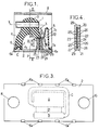
- la figure 1 est une vue en coupe d'une forme de réalisation de l'invention, la coupe étant prise selon la ligne I-I de la figure 2,
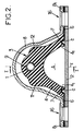
- la figure 2 est une vue en coupe selon la ligne II-II de la figure 1,
- la figure 3 est une vue de dessous du dispositif des figures 1 et 2,
- et la figure 4 est une vue de détail en coupe du dispositif de la figure 1, la coupe étant prise selon la ligne IV-IV de la figure 1.
- Sur les différentes figures, les mêmes références désignent des éléments identiques ou similaires.
- Le support antivibratoire représenté sur les dessins comporte deux armatures métalliques rigides 1 et 2 qui sont reliées entre elles par un corps en élastomère 3.
- La première armature 1 est tubulaire dans l'exemple représenté, et présente un axe longitudinal X. De façon plus générale, la première armature 1 peut avoir la forme d'un organe allongé plein ou creux, de section circulaire ou non.
- La deuxième armature 2, quant à elle, est une plaque appelée ci-après plaque de base, qui présente une forme générale plane au moins par morceaux, et qui s'étend parallèlement à l'axe X de la première armature.
- Le corps en élastomère 3 est solidarisé avec la première armature 1 par vulcanisation. Il comporte une paroi épaisse 4 sensiblement en forme de cloche, qui s'étend depuis un sommet solidaire de la première armature 1 jusqu'à une base périphérique 4₁ solidaire de la plaque de base 2, selon une direction Z dans laquelle on souhaite amortir des mouvements vibratoires entre les deux armatures. La direction Z est perpendiculaire à l'axe X et au plan général de la plaque de base 2, et elle peut être par exemple verticale.
- La paroi épaisse 4 présente une résistance à la compression suffisante pour supporter une charge appliquée à la première armature 1 parallèlement à l'axe Z et dirigée vers la plaque de base. Cette charge peut être par exemple supérieure à 15 kg, en général très supérieure.
- La base périphérique 4₁ de la paroi épaisse est solidarisée de façon étanche avec la plaque de base 2, en délimitant ainsi une chambre de travail A. Dans l'exemple représenté, la chambre A présente une section horizontale rectangulaire, mais elle pourrait avoir d'autres formes, notamment à section horizontale circulaire ou ovale.
- Par ailleurs, le corps en élastomère 3 comporte en outre une paroi mince 5, souple, qui est juxtaposée à la paroi épaisse 4 et formée d'une seule pièce avec celle-ci.
- La paroi mince 5 présente une forme de cloche, avec une base périphérique 5₁ qui est solidarisée de façon étanche avec la plaque de base 2, en délimitant ainsi une chambre de compensation B.
- Cette chambre B présente une section horizontale rectangulaire dans l'exemple représenté, mais elle pourrait présenter une forme différente.
- De préférence, les parois 4 et 5 ne présentent pas de partie commune entre les chambres A et B, en dehors de la liaison entre leurs bases 4₁ et 5₁.
- Les deux chambres A et B communiquent par l'intermédiaire d'un canal étroit C, qui a la forme d'une gorge creusée dans la face du corps en élastomère 3 qui est appliquée contre la plaque de base 2, les bords de la gorge étant en contact étanche contre la plaque de base 2.
- De plus, dans l'exemple représenté, le corps en élastomère 3 est surmoulé sur une plaque métallique ajourée 6, disposée sur la face du corps en élastomère qui est en contact avec la plaque de base 2. Ainsi, la plaque de base 2 peut être solidarisée avec le corps en élastomère par sertissage de pattes 6a de la plaque ajourée 6 sur la plaque de base 2, ou éventuellement par sertissage de ladite plaque de base 2 sur ladite plaque ajourée 6.
- En outre, la plaque ajourée 6 comporte une gorge ou gouttière 7 qui détermine la forme du canal étroit C, avec une grande précision.
- Par ailleurs, le support antivibratoire comporte en outre un arceau 8 métallique qui est fixé de façon rigide à la plaque de base 2. L'arceau 8 entoure la première armature 1 et le corps en élastomère 3, et il s'étend parallèlement à l'axe X.
- Dans l'exemple représenté, l'arceau 8 est une plaque pliée, qui recouvre la totalité du corps en élastomère, de façon à le protéger contre les chocs de corps extérieurs. Ceci est avantageux dans la mesure où la paroi mince 5 est fragile et exposée à côté de la paroi épaisse 4.
- L'arceau 8 comporte deux prolongements latéraux 8₁, respectivement de chaque côté du corps en élastomère 3. Ces prolongements latéraux recouvrent chacun une partie de la plaque ajourée 6, qui elle-même recouvre la deuxième armature. De plus, ces trois éléments sont traversés par un perçage 16 au niveau de chaque prolongement 8₁.
- Ces perçages 16 permettent de fixer le support antivibratoire sur une pièce rigide, au moyen de vis ou de boulons (non représentés), en complétant en outre la solidarisation des différentes parties du support antivibratoire par serrage des prolongements 8₁ sur la plaque 6 et la deuxième armature 2.
- Pour coopérer avec l'arceau 8, le corps en élastomère 3 comporte un premier bossage 9, qui s'étend parallèlement à la direction Z à partir de la première armature 1, en direction opposée à la plaque de base 2. Ce bossage 9 est adapté à buter contre la partie supérieure de l'arceau 8, en limitant ainsi le déplacement de la première armature en éloignement par rapport à la plaque de base 2.
- Le corps en élastomère comporte en outre des bossages latéraux 11, 12 sensiblement diamétralement opposés par rapport à la première armature 1, qui sont adaptés à buter contre l'arceau 8 lorsque la première armature est déplacée sensiblement perpendiculairement à l'axe X et à la direction Z.
- Les chambres A et B, ainsi que le canal étroit C, sont remplis de liquide. Lorsque les deux armatures 1 et 2 subissent des mouvements relatifs de vibration, la paroi épaisse 4 du corps en élastomère se déforme, ce qui provoque des variations de volume de la chambre de travail A. Ces variations de volume entraînent des transferts de liquide entre les chambres A et B, par l'intermédiaire du canal étroit C, les variations de volume de la chambre de travail A étant compensées par des variations complémentaires de la chambre de compensation B, dont la paroi mince 5 est facilement déformable.
- Au voisinage d'une certaine fréquence, qui est généralement inférieure à 20 hertz et qui dépend essentiellement des dimensions du canal étroit C et de la masse volumique du liquide en mouvement dans ledit canal étroit, il se produit dans le canal étroit C un phénomène de résonance qui, en liaison avec les pertes de charge dans ledit canal étroit, provoque un fort amortissement des vibrations entre les deux armatures 1 et 2.
- Par ailleurs, le support antivibratoire comporte un clapet de découplage, destiné à filtrer les vibrations de faible amplitude, par exemple inférieure à 0,5 mm, et de fréquence relativement élevée, par exemple supérieure à 20 hertz.
- Ce clapet de découplage est constitué par une lamelle souple 20 qui est formée d'une seule pièce avec la base 4₁ du corps en élastomère 3, cette lamelle 20 étant insérée dans un logement 22 d'une partie saillante 21 de la plaque de base 2.
- La partie saillante 21 s'étend parallèlement à la direction principale de vibration Z à partir de la plaque de base 2, en direction de la première armature 1, et elle est solidarisée à la base 4₁ de la paroi épaisse 4, avec étanchéité.
- La partie saillante 21 est de préférence formée d'une seule pièce avec la plaque de base, laquelle plaque de base peut alors avantageusement être réalisée en aluminium moulé, ou éventuellement en matière plastique moulée.
- Le logement 22 s'étend parallèlement à la direction principale de vibration Z et il débouche à l'extrémité 21a de la partie saillante 21 la plus proche de la première armature 1. Cette extrémité 21a est recouverte par la partie de la base 4₁ qui comporte la lamelle 20, ladite extrémité 21a et ladite partie de la base 4₁ étant solidaires et en contact étanche l'une avec l'autre.
- Le logement 22 présente une forme de fente avec deux faces principales internes 23, 24 disposées parallèlement à la lamelle 20 et au voisinage de celle-ci, c'est-à-dire avec un jeu de la lamelle 20 dans le logement 22 qui peut être par exemple de l'ordre de 0,5 mm perpendiculairement au plan de la lamelle 20.
- La partie saillante 21 comporte deux faces latérales principales 27, 28 qui sont parallèles à la lamelle 20 et qui sont au contact respectivement de la chambre de travail A et de la chambre de compensation B, et deux faces latérales étroites 29 qui sont en contact étanche avec la base 4₁ de la paroi épaisse du corps en élastomère et solidaires de cette base 4₁.
- Les faces 27, 28 sont percées d'orifices, respectivement 25, 26, qui font communiquer respectivement la face interne 23 du logement 22 avec la chambre de travail A et la face interne 24 du logement 22 avec la chambre de compensation B.
- Lorsque la première armature 1 ou la plaque de base 2 est soumise à des vibrations de faible amplitude et de relativement haute fréquence, la lamelle 20 est elle-même entraînée en vibration, et ce phénomène suffit pour assurer un effet de filtrage empêchant le transfert des vibrations d'une armature à l'autre.
- Lorsque l'amplitude des vibrations imposées à l'une des armatures est suffisamment forte pour que la lamelle 20 vienne en butée contre l'une ou l'autre des faces internes 23, 24 du logement 22, la lamelle 20 obture tour à tour les orifices 25 et 26, de sorte que le liquide est forcé de circuler dans le canal étroit C entre la chambre de travail A et la chambre de compensation B.
- On notera que le canal étroit peut éventuellement être réalisé en ménageant une rainure dans la plaque de base 2 lors de son moulage, en remplacement de la gorge décrite ci-dessus formée dans le corps en élastomère.
Claims (7)
- Support antivibratoire hydraulique, destiné à être interposé entre deux éléments rigides pour amortir des vibrations entre ces deux éléments, essentiellement selon une direction principale de vibration (Z), ce support comportant une première (1) et une deuxième (2) armatures rigides, solidarisables respectivement avec les deux éléments rigides à réunir, et un corps en élastomère (3) qui présente une paroi épaisse (4) reliant entre elles les deux armatures rigides (1, 2) et délimitant partiellement une chambre de travail (A), cette paroi épaisse (4) présentant sensiblement une forme de cloche qui s'étend selon la direction principale de vibration (Z) entre d'une part une base périphérique (4₁) solidaire de la deuxième armature (2) et d'autre part un sommet solidaire de la première armature (1), ce corps en élastomère (3) comportant en outre une paroi mince (5) librement déformable qui est formée d'une seule pièce avec la paroi épaisse (4) susmentionnée et qui délimite partiellement une chambre de compensation (B) communiquant avec la chambre de travail (A) par un canal étroit (C), les deux chambres (A, B) et le canal étroit (C) étant remplis d'un liquide, la deuxième armature (2) étant une plaque de base qui s'étend selon un plan général sensiblement perpendiculaire à la direction principale de vibration (Z) et qui présente une face dite de support, solidarisée de façon étanche avec le corps en élastomère pour délimiter avec celui-ci les deux chambres (A, B) et le canal étroit (C),
caractérisé en ce que la base (4₁) du corps en élastomère (3) est formée d'une seule pièce avec une lamelle (20) souple en élastomère qui s'étend à partir de cette base parallèlement à la direction principale de vibration (Z) en direction de la plaque de base (2), ladite plaque de base comportant un logement (22) en forme de fente qui reçoit la lamelle (20), ce logement (22) présentant une épaisseur légèrement supérieure à la lamelle (20) et comportant une première et une deuxième faces internes (23, 24) disposées parallèlement à la lamelle (20) et en regard de celle-ci, la première face interne présentant au moins un orifice (25) qui communique avec la chambre de travail (A) et la deuxième face interne comportant au moins un orifice (26) qui communique avec la chambre de compensation (B), et la lamelle (20) étant adaptée pour obturer l'un ou l'autre de ces orifices en fonction des déplacements de liquide entre la chambre de travail et la chambre de compensation, la lamelle (20) et le logement (22) formant ainsi un clapet de découplage. - Support antivibratoire hydraulique selon la revendication 1, dans lequel la plaque de base (2) comporte une partie saillante (21) qui s'étend en direction de la première armature (1) parallèlement à la direction principale de vibration (Z), le logement (22) en forme de fente étant formé dans cette partie saillante (21), et ladite partie saillante formant une cloison entre la chambre de travail (A) et la chambre de compensation (B).
- Support antivibratoire hydraulique selon l'une quelconque des revendication 1 et 2, dans lequel la plaque de base est une pièce moulée.
- Support antivibratoire hydraulique selon la revendication 3, dans lequel la plaque de base (2) est réalisée en aluminium.
- Support antivibratoire hydraulique selon la revendication 3, dans lequel la plaque de base (2) est réalisée en matière plastique.
- Support antivibratoire hydraulique selon l'une quelconque des revendications 3 à 5, dans lequel le canal étroit est constitué par une rainure formée dans la face de support de la plaque de base.
- Support antivibratoire hydraulique selon l'une quelconque des revendications précédentes, dans lequel la paroi mince (5) du corps en élastomère présente une forme de cloche, les chambres de travail (A) et de compensation (B) étant juxtaposées de façon non concentrique sur la face de support de la plaque de base (2).
Applications Claiming Priority (2)
| Application Number | Priority Date | Filing Date | Title |
|---|---|---|---|
| FR9412889A FR2726339B1 (fr) | 1994-10-27 | 1994-10-27 | Perfectionnements aux supports antivibratoires hydrauliques |
| FR9412889 | 1994-10-27 |
Publications (2)
| Publication Number | Publication Date |
|---|---|
| EP0709593A1 true EP0709593A1 (fr) | 1996-05-01 |
| EP0709593B1 EP0709593B1 (fr) | 1998-05-27 |
Family
ID=9468287
Family Applications (3)
| Application Number | Title | Priority Date | Filing Date |
|---|---|---|---|
| EP95402372A Expired - Lifetime EP0709593B1 (fr) | 1994-10-27 | 1995-10-24 | Perfectionnements aux supports antivibratoires hydrauliques |
| EP95402373A Expired - Lifetime EP0709594B1 (fr) | 1994-10-27 | 1995-10-24 | Perfectionnements aux supports antivibratoires hydrauliques |
| EP95936619A Expired - Lifetime EP0787266B1 (fr) | 1994-10-27 | 1995-10-27 | Support antivibratoire hydraulique |
Family Applications After (2)
| Application Number | Title | Priority Date | Filing Date |
|---|---|---|---|
| EP95402373A Expired - Lifetime EP0709594B1 (fr) | 1994-10-27 | 1995-10-24 | Perfectionnements aux supports antivibratoires hydrauliques |
| EP95936619A Expired - Lifetime EP0787266B1 (fr) | 1994-10-27 | 1995-10-27 | Support antivibratoire hydraulique |
Country Status (7)
| Country | Link |
|---|---|
| US (3) | US5549283A (fr) |
| EP (3) | EP0709593B1 (fr) |
| JP (2) | JP3568652B2 (fr) |
| DE (3) | DE69503737T2 (fr) |
| ES (2) | ES2116052T3 (fr) |
| FR (1) | FR2726339B1 (fr) |
| WO (1) | WO1996013675A1 (fr) |
Cited By (1)
| Publication number | Priority date | Publication date | Assignee | Title |
|---|---|---|---|---|
| EP0931956A1 (fr) * | 1998-01-22 | 1999-07-28 | Draftex Industries Limited | Appareil pour l'amortissement des vibrations |
Families Citing this family (21)
| Publication number | Priority date | Publication date | Assignee | Title |
|---|---|---|---|---|
| FR2726339B1 (fr) * | 1994-10-27 | 1996-12-27 | Hutchinson | Perfectionnements aux supports antivibratoires hydrauliques |
| DE19632771C1 (de) * | 1996-08-14 | 1998-02-12 | Basf Ag | Elastisches Lager, insbesondere zur Lagerung eines Motors in einem Kraftfahrzeug |
| DE19640204A1 (de) * | 1996-09-30 | 1998-04-02 | Zeiss Carl Fa | Hydraulische Lagerzelle |
| FR2756342B1 (fr) | 1996-11-28 | 1999-01-29 | Hutchinson | Support antivibratoire et vehicule automobile comportant un tel support |
| FR2757237B1 (fr) * | 1996-12-16 | 1999-02-19 | Hutchinson | Support antivibratoire hydraulique |
| FR2762654B1 (fr) * | 1997-04-28 | 1999-07-09 | Hutchinson | Dispositif antivibratoire |
| FR2766890B1 (fr) * | 1997-08-01 | 1999-10-08 | Hutchinson | Support antivibratoire hydraulique |
| FR2766892B1 (fr) * | 1997-08-01 | 1999-10-01 | Hutchinson | Support antivibratoire hydraulique |
| FR2766893B1 (fr) * | 1997-08-01 | 1999-10-08 | Hutchinson | Support antivibratoire hydraulique |
| FR2766891B1 (fr) * | 1997-08-01 | 1999-10-08 | Hutchinson | Support antivibratoire hydraulique |
| FR2778716B1 (fr) * | 1998-05-13 | 2000-08-04 | Peugeot | Support hydroelastique interpose entre un groupe motopropulseur et une caisse d'un vehicule automobile |
| FR2779198B1 (fr) * | 1998-05-28 | 2000-08-04 | Hutchinson | Support antivibratoire |
| FR2796114B1 (fr) * | 1999-07-08 | 2002-05-17 | Peugeot Citroen Automobiles Sa | Support hydroelastique pour la suspension d'un groupe motopropulseur dans un vehicule automobile |
| FR2823817B1 (fr) * | 2001-04-20 | 2003-10-31 | C F Gomma Barre Thomas | Support anti-vibratoire hydroelastique |
| DE10146154B4 (de) * | 2001-09-19 | 2007-04-26 | Trelleborg Automotive Technical Centre Gmbh | Hydraulisch dämpfende Buchse |
| ITTO20020128A1 (it) * | 2002-02-15 | 2003-08-18 | Gomma C F Spa | Supporto idroelastico, particolarmente per un motore a combustione interna. |
| DE10232393B4 (de) * | 2002-07-17 | 2008-06-19 | Trelleborg Automotive Technical Centre Gmbh | Hydraulisch dämpfende Buchse |
| US7306104B2 (en) * | 2003-02-12 | 2007-12-11 | Z Screen Llc | Method and apparatus for separating fine particulate matter from other materials |
| DE102007032957C5 (de) * | 2007-07-14 | 2023-08-17 | Contitech Vibration Control Gmbh | Elastisches Lager |
| FR2930614B1 (fr) * | 2008-04-29 | 2010-05-14 | Hutchinson | Dispositif antivibratoire, systeme antivibratoire comprenant un tel dispositif et procede de fabrication |
| JP6347226B2 (ja) * | 2015-04-16 | 2018-06-27 | トヨタ自動車株式会社 | スタビライザバー取付装置、スタビライザバー取付用ブラケット |
Citations (9)
| Publication number | Priority date | Publication date | Assignee | Title |
|---|---|---|---|---|
| EP0012638A1 (fr) * | 1978-12-07 | 1980-06-25 | Automobiles Peugeot | Cale élastique, notamment pour la suspension d'un moteur de véhicule |
| EP0172700A1 (fr) * | 1984-08-07 | 1986-02-26 | Avon Industrial Polymers Limited | Dispositif de montage à amortissement hydraulique |
| EP0236199A1 (fr) | 1986-02-25 | 1987-09-09 | Automobiles Peugeot | Support hydroélastique, notamment pour moteur de véhicule |
| GB2200190A (en) * | 1986-12-23 | 1988-07-27 | Nissan Motor | Fluid filled power unit mount |
| GB2207214A (en) * | 1987-06-19 | 1989-01-25 | Nissan Motor | Vibration insulating device |
| FR2622269A1 (fr) * | 1987-10-26 | 1989-04-28 | Freudenberg Carl | Ressort a douille en caoutchouc |
| DE3935499A1 (de) * | 1989-10-25 | 1991-05-02 | Gmt Gummi Metall Technik Gmbh | Kombinierte gummi-gasfeder |
| EP0556076A1 (fr) * | 1992-02-10 | 1993-08-18 | Automobiles Peugeot | Support hydroélastique |
| EP0646735A1 (fr) * | 1993-10-05 | 1995-04-05 | Hutchinson | Perfectionnements aux supports antivibratoires hydrauliques |
Family Cites Families (14)
| Publication number | Priority date | Publication date | Assignee | Title |
|---|---|---|---|---|
| US3698703A (en) * | 1970-11-23 | 1972-10-17 | Gen Tire & Rubber Co | Dual rate fluid damped elastomeric bushing |
| CA1194045A (fr) * | 1981-09-30 | 1985-09-24 | Isao Ozawa | Amortisseur elastique pour suspension de moteur |
| JPS5937348A (ja) * | 1982-08-23 | 1984-02-29 | Tokai Rubber Ind Ltd | 防振ゴムマウント |
| DE3443618A1 (de) * | 1984-11-29 | 1986-06-05 | Metzeler Kautschuk GmbH, 8000 München | Motorlager mit hydraulischer daempfung |
| JPS63172036A (ja) * | 1987-01-07 | 1988-07-15 | Nissan Motor Co Ltd | 内外筒型流体封入式パワ−ユニツトマウント |
| DE3730582A1 (de) * | 1987-09-11 | 1989-03-23 | Opel Adam Ag | Lager zur elastischen, schwingungsdaempfenden lagerung von bauteilen |
| JPH0629639B2 (ja) * | 1988-02-25 | 1994-04-20 | 丸五ゴム工業株式会社 | 液封型弾性のブッシュのストッパー装置 |
| JPH01220737A (ja) * | 1988-02-25 | 1989-09-04 | Toyo Tire & Rubber Co Ltd | 組合わせ形液封入防振マウント |
| JPH01229130A (ja) * | 1988-03-07 | 1989-09-12 | Bridgestone Corp | 防振装置 |
| JPH01168036U (fr) * | 1988-05-18 | 1989-11-27 | ||
| DE3841193A1 (de) * | 1988-12-07 | 1990-06-21 | Boge Ag | Hydraulisch daempfendes gummilager |
| JP2972289B2 (ja) * | 1990-06-29 | 1999-11-08 | 日産自動車株式会社 | 防振装置 |
| JPH06264965A (ja) * | 1993-03-13 | 1994-09-20 | Toyoda Gosei Co Ltd | 車両用エンジンマウント |
| FR2726339B1 (fr) * | 1994-10-27 | 1996-12-27 | Hutchinson | Perfectionnements aux supports antivibratoires hydrauliques |
-
1994
- 1994-10-27 FR FR9412889A patent/FR2726339B1/fr not_active Expired - Fee Related
-
1995
- 1995-10-24 EP EP95402372A patent/EP0709593B1/fr not_active Expired - Lifetime
- 1995-10-24 ES ES95402372T patent/ES2116052T3/es not_active Expired - Lifetime
- 1995-10-24 DE DE69503737T patent/DE69503737T2/de not_active Expired - Fee Related
- 1995-10-24 EP EP95402373A patent/EP0709594B1/fr not_active Expired - Lifetime
- 1995-10-24 ES ES95402373T patent/ES2119336T3/es not_active Expired - Lifetime
- 1995-10-24 DE DE69502682T patent/DE69502682T2/de not_active Expired - Fee Related
- 1995-10-26 US US08/548,857 patent/US5549283A/en not_active Expired - Fee Related
- 1995-10-26 US US08/548,547 patent/US5741001A/en not_active Expired - Fee Related
- 1995-10-27 DE DE69502027T patent/DE69502027T2/de not_active Expired - Fee Related
- 1995-10-27 WO PCT/FR1995/001425 patent/WO1996013675A1/fr not_active Ceased
- 1995-10-27 JP JP28022795A patent/JP3568652B2/ja not_active Expired - Fee Related
- 1995-10-27 EP EP95936619A patent/EP0787266B1/fr not_active Expired - Lifetime
- 1995-10-27 US US08/817,622 patent/US5855352A/en not_active Expired - Fee Related
- 1995-10-27 JP JP28012595A patent/JP3604213B2/ja not_active Expired - Fee Related
Patent Citations (9)
| Publication number | Priority date | Publication date | Assignee | Title |
|---|---|---|---|---|
| EP0012638A1 (fr) * | 1978-12-07 | 1980-06-25 | Automobiles Peugeot | Cale élastique, notamment pour la suspension d'un moteur de véhicule |
| EP0172700A1 (fr) * | 1984-08-07 | 1986-02-26 | Avon Industrial Polymers Limited | Dispositif de montage à amortissement hydraulique |
| EP0236199A1 (fr) | 1986-02-25 | 1987-09-09 | Automobiles Peugeot | Support hydroélastique, notamment pour moteur de véhicule |
| GB2200190A (en) * | 1986-12-23 | 1988-07-27 | Nissan Motor | Fluid filled power unit mount |
| GB2207214A (en) * | 1987-06-19 | 1989-01-25 | Nissan Motor | Vibration insulating device |
| FR2622269A1 (fr) * | 1987-10-26 | 1989-04-28 | Freudenberg Carl | Ressort a douille en caoutchouc |
| DE3935499A1 (de) * | 1989-10-25 | 1991-05-02 | Gmt Gummi Metall Technik Gmbh | Kombinierte gummi-gasfeder |
| EP0556076A1 (fr) * | 1992-02-10 | 1993-08-18 | Automobiles Peugeot | Support hydroélastique |
| EP0646735A1 (fr) * | 1993-10-05 | 1995-04-05 | Hutchinson | Perfectionnements aux supports antivibratoires hydrauliques |
Non-Patent Citations (1)
| Title |
|---|
| PATENT ABSTRACTS OF JAPAN vol. 8, no. 140 (M - 305)<1577> 29 June 1984 (1984-06-29) * |
Cited By (1)
| Publication number | Priority date | Publication date | Assignee | Title |
|---|---|---|---|---|
| EP0931956A1 (fr) * | 1998-01-22 | 1999-07-28 | Draftex Industries Limited | Appareil pour l'amortissement des vibrations |
Also Published As
| Publication number | Publication date |
|---|---|
| JP3568652B2 (ja) | 2004-09-22 |
| DE69503737T2 (de) | 1999-03-25 |
| JP3604213B2 (ja) | 2004-12-22 |
| US5855352A (en) | 1999-01-05 |
| ES2119336T3 (es) | 1998-10-01 |
| US5549283A (en) | 1996-08-27 |
| EP0787266B1 (fr) | 1998-04-08 |
| EP0709593B1 (fr) | 1998-05-27 |
| EP0787266A1 (fr) | 1997-08-06 |
| DE69503737D1 (de) | 1998-09-03 |
| FR2726339B1 (fr) | 1996-12-27 |
| JPH08210426A (ja) | 1996-08-20 |
| JPH08210427A (ja) | 1996-08-20 |
| FR2726339A1 (fr) | 1996-05-03 |
| DE69502682D1 (de) | 1998-07-02 |
| ES2116052T3 (es) | 1998-07-01 |
| DE69502027D1 (de) | 1998-05-14 |
| DE69502682T2 (de) | 1999-01-21 |
| WO1996013675A1 (fr) | 1996-05-09 |
| DE69502027T2 (de) | 1998-08-13 |
| US5741001A (en) | 1998-04-21 |
| EP0709594A1 (fr) | 1996-05-01 |
| EP0709594B1 (fr) | 1998-07-29 |
Similar Documents
| Publication | Publication Date | Title |
|---|---|---|
| EP0709593B1 (fr) | Perfectionnements aux supports antivibratoires hydrauliques | |
| EP0072262B1 (fr) | Cale élastique, notamment pour la suspension d'un moteur de véhicule | |
| EP0646735B1 (fr) | Perfectionnements aux supports antivibratoires hydrauliques | |
| EP1176335B1 (fr) | Procédé de fabrication d'un support anti-vibratoire hydraulique | |
| EP0236199B1 (fr) | Support hydroélastique, notamment pour moteur de véhicule | |
| FR2812363A1 (fr) | Manchon antivibratoire hydraulique | |
| EP0818639A1 (fr) | Dispositif antivibratoire hydraulique | |
| EP1304498A1 (fr) | Support antivibratoire hydraulique | |
| EP0097091A1 (fr) | Amortisseur de vibrations et notamment adaptateur de fréquence pour pale d'hélicoptère | |
| EP1489335B1 (fr) | Support antivibratoire hydraulique | |
| FR2973463A1 (fr) | Dispositif d'amortissement de vibration rempli de fluide du type a amortissement de vibration multidirectionnel | |
| EP0957286B1 (fr) | Support hydroélastique interposé entre un groupe motopropulseur et une caisse d'un véhicule automobile | |
| FR2702021A1 (fr) | Support hydroélastique modulaire. | |
| FR2832477A1 (fr) | Cale hydroelastique | |
| FR2714947A1 (fr) | Perfectionnements aux dispositifs antivibratoires hydrauliques. | |
| EP1067309B1 (fr) | Support hydroélastique pour un groupe motopropulseur d'un véhicule automobile. | |
| EP0894996B1 (fr) | Support antivibratoire hydraulique | |
| EP3742018B1 (fr) | Support antivibratoire hydraulique | |
| EP1074761B1 (fr) | Support hydroélastique, notamment pour la suspension d'un groupe motopropulseur dans la caisse d'un véhicule automobile | |
| EP0957285B1 (fr) | Support hydroélastique, notamment pour la suspension d'un groupe motopropulseur dans la caisse d'un véhicule automobiles | |
| FR2756342A1 (fr) | Support antivibratoire et vehicule automobile comportant un tel support | |
| FR2796114A1 (fr) | Support hydroelastique pour la suspension d'un groupe motopropulseur dans un vehicule automobile | |
| FR2739669A1 (fr) | Support antivibratoire hydraulique | |
| EP0848184A1 (fr) | Support antivibratoire hydraulique | |
| FR2831631A1 (fr) | Support antivibratoire hydraulique |
Legal Events
| Date | Code | Title | Description |
|---|---|---|---|
| PUAI | Public reference made under article 153(3) epc to a published international application that has entered the european phase |
Free format text: ORIGINAL CODE: 0009012 |
|
| AK | Designated contracting states |
Kind code of ref document: A1 Designated state(s): BE DE ES FR GB IT NL PT SE |
|
| 17P | Request for examination filed |
Effective date: 19960524 |
|
| 17Q | First examination report despatched |
Effective date: 19970630 |
|
| GRAG | Despatch of communication of intention to grant |
Free format text: ORIGINAL CODE: EPIDOS AGRA |
|
| GRAG | Despatch of communication of intention to grant |
Free format text: ORIGINAL CODE: EPIDOS AGRA |
|
| GRAH | Despatch of communication of intention to grant a patent |
Free format text: ORIGINAL CODE: EPIDOS IGRA |
|
| GRAH | Despatch of communication of intention to grant a patent |
Free format text: ORIGINAL CODE: EPIDOS IGRA |
|
| GRAA | (expected) grant |
Free format text: ORIGINAL CODE: 0009210 |
|
| ITF | It: translation for a ep patent filed | ||
| AK | Designated contracting states |
Kind code of ref document: B1 Designated state(s): BE DE ES FR GB IT NL PT SE |
|
| PG25 | Lapsed in a contracting state [announced via postgrant information from national office to epo] |
Ref country code: NL Free format text: LAPSE BECAUSE OF FAILURE TO SUBMIT A TRANSLATION OF THE DESCRIPTION OR TO PAY THE FEE WITHIN THE PRESCRIBED TIME-LIMIT Effective date: 19980527 |
|
| GBT | Gb: translation of ep patent filed (gb section 77(6)(a)/1977) |
Effective date: 19980528 |
|
| REG | Reference to a national code |
Ref country code: ES Ref legal event code: FG2A Ref document number: 2116052 Country of ref document: ES Kind code of ref document: T3 |
|
| REF | Corresponds to: |
Ref document number: 69502682 Country of ref document: DE Date of ref document: 19980702 |
|
| PG25 | Lapsed in a contracting state [announced via postgrant information from national office to epo] |
Ref country code: SE Free format text: LAPSE BECAUSE OF FAILURE TO SUBMIT A TRANSLATION OF THE DESCRIPTION OR TO PAY THE FEE WITHIN THE PRESCRIBED TIME-LIMIT Effective date: 19980827 Ref country code: PT Free format text: LAPSE BECAUSE OF FAILURE TO SUBMIT A TRANSLATION OF THE DESCRIPTION OR TO PAY THE FEE WITHIN THE PRESCRIBED TIME-LIMIT Effective date: 19980827 |
|
| PG25 | Lapsed in a contracting state [announced via postgrant information from national office to epo] |
Ref country code: BE Free format text: LAPSE BECAUSE OF NON-PAYMENT OF DUE FEES Effective date: 19981031 |
|
| NLV1 | Nl: lapsed or annulled due to failure to fulfill the requirements of art. 29p and 29m of the patents act | ||
| PLBE | No opposition filed within time limit |
Free format text: ORIGINAL CODE: 0009261 |
|
| STAA | Information on the status of an ep patent application or granted ep patent |
Free format text: STATUS: NO OPPOSITION FILED WITHIN TIME LIMIT |
|
| BERE | Be: lapsed |
Owner name: HUTCHINSON Effective date: 19981031 |
|
| 26N | No opposition filed | ||
| REG | Reference to a national code |
Ref country code: GB Ref legal event code: IF02 |
|
| PGFP | Annual fee paid to national office [announced via postgrant information from national office to epo] |
Ref country code: DE Payment date: 20061009 Year of fee payment: 12 |
|
| PGFP | Annual fee paid to national office [announced via postgrant information from national office to epo] |
Ref country code: GB Payment date: 20061010 Year of fee payment: 12 |
|
| PGFP | Annual fee paid to national office [announced via postgrant information from national office to epo] |
Ref country code: ES Payment date: 20061016 Year of fee payment: 12 |
|
| PGFP | Annual fee paid to national office [announced via postgrant information from national office to epo] |
Ref country code: IT Payment date: 20061031 Year of fee payment: 12 |
|
| PGFP | Annual fee paid to national office [announced via postgrant information from national office to epo] |
Ref country code: FR Payment date: 20071029 Year of fee payment: 13 |
|
| GBPC | Gb: european patent ceased through non-payment of renewal fee |
Effective date: 20071024 |
|
| PG25 | Lapsed in a contracting state [announced via postgrant information from national office to epo] |
Ref country code: DE Free format text: LAPSE BECAUSE OF NON-PAYMENT OF DUE FEES Effective date: 20080501 |
|
| PG25 | Lapsed in a contracting state [announced via postgrant information from national office to epo] |
Ref country code: GB Free format text: LAPSE BECAUSE OF NON-PAYMENT OF DUE FEES Effective date: 20071024 |
|
| REG | Reference to a national code |
Ref country code: ES Ref legal event code: FD2A Effective date: 20071025 |
|
| PG25 | Lapsed in a contracting state [announced via postgrant information from national office to epo] |
Ref country code: ES Free format text: LAPSE BECAUSE OF NON-PAYMENT OF DUE FEES Effective date: 20071025 |
|
| REG | Reference to a national code |
Ref country code: FR Ref legal event code: ST Effective date: 20090630 |
|
| PG25 | Lapsed in a contracting state [announced via postgrant information from national office to epo] |
Ref country code: IT Free format text: LAPSE BECAUSE OF NON-PAYMENT OF DUE FEES Effective date: 20071024 |
|
| PG25 | Lapsed in a contracting state [announced via postgrant information from national office to epo] |
Ref country code: FR Free format text: LAPSE BECAUSE OF NON-PAYMENT OF DUE FEES Effective date: 20081031 |