EP0709623B1 - Equipment for the combustion of fluids with high particle content - Google Patents
Equipment for the combustion of fluids with high particle content Download PDFInfo
- Publication number
- EP0709623B1 EP0709623B1 EP95115763A EP95115763A EP0709623B1 EP 0709623 B1 EP0709623 B1 EP 0709623B1 EP 95115763 A EP95115763 A EP 95115763A EP 95115763 A EP95115763 A EP 95115763A EP 0709623 B1 EP0709623 B1 EP 0709623B1
- Authority
- EP
- European Patent Office
- Prior art keywords
- tank
- pump
- combustion
- suspension
- equipment
- Prior art date
- Legal status (The legal status is an assumption and is not a legal conclusion. Google has not performed a legal analysis and makes no representation as to the accuracy of the status listed.)
- Expired - Lifetime
Links
- 239000002245 particle Substances 0.000 title claims description 13
- 238000002485 combustion reaction Methods 0.000 title claims description 6
- 239000012530 fluid Substances 0.000 title description 3
- OKTJSMMVPCPJKN-UHFFFAOYSA-N Carbon Chemical compound [C] OKTJSMMVPCPJKN-UHFFFAOYSA-N 0.000 claims description 12
- 229910052799 carbon Inorganic materials 0.000 claims description 12
- 239000000725 suspension Substances 0.000 claims description 11
- 239000007788 liquid Substances 0.000 claims description 9
- 239000007787 solid Substances 0.000 claims description 3
- 238000003756 stirring Methods 0.000 claims description 2
- 239000000428 dust Substances 0.000 description 9
- 230000005540 biological transmission Effects 0.000 description 2
- 238000005086 pumping Methods 0.000 description 2
- 239000002699 waste material Substances 0.000 description 2
- XAGFODPZIPBFFR-UHFFFAOYSA-N aluminium Chemical compound [Al] XAGFODPZIPBFFR-UHFFFAOYSA-N 0.000 description 1
- 229910052782 aluminium Inorganic materials 0.000 description 1
- 239000004411 aluminium Substances 0.000 description 1
- 239000000571 coke Substances 0.000 description 1
- 230000001419 dependent effect Effects 0.000 description 1
- 238000000151 deposition Methods 0.000 description 1
- 238000006073 displacement reaction Methods 0.000 description 1
- 230000007613 environmental effect Effects 0.000 description 1
- 239000000835 fiber Substances 0.000 description 1
- 238000010438 heat treatment Methods 0.000 description 1
- 238000012423 maintenance Methods 0.000 description 1
- 239000000463 material Substances 0.000 description 1
- 238000000034 method Methods 0.000 description 1
- 238000002156 mixing Methods 0.000 description 1
- 239000002244 precipitate Substances 0.000 description 1
- 238000001556 precipitation Methods 0.000 description 1
- 230000001105 regulatory effect Effects 0.000 description 1
- 238000007789 sealing Methods 0.000 description 1
Images

Classifications
-
- F—MECHANICAL ENGINEERING; LIGHTING; HEATING; WEAPONS; BLASTING
- F23—COMBUSTION APPARATUS; COMBUSTION PROCESSES
- F23K—FEEDING FUEL TO COMBUSTION APPARATUS
- F23K5/00—Feeding or distributing other fuel to combustion apparatus
- F23K5/02—Liquid fuel
- F23K5/14—Details thereof
- F23K5/142—Fuel pumps
-
- F—MECHANICAL ENGINEERING; LIGHTING; HEATING; WEAPONS; BLASTING
- F23—COMBUSTION APPARATUS; COMBUSTION PROCESSES
- F23G—CREMATION FURNACES; CONSUMING WASTE PRODUCTS BY COMBUSTION
- F23G7/00—Incinerators or other apparatus for consuming industrial waste, e.g. chemicals
- F23G7/001—Incinerators or other apparatus for consuming industrial waste, e.g. chemicals for sludges or waste products from water treatment installations
-
- F—MECHANICAL ENGINEERING; LIGHTING; HEATING; WEAPONS; BLASTING
- F23—COMBUSTION APPARATUS; COMBUSTION PROCESSES
- F23G—CREMATION FURNACES; CONSUMING WASTE PRODUCTS BY COMBUSTION
- F23G7/00—Incinerators or other apparatus for consuming industrial waste, e.g. chemicals
- F23G7/008—Incinerators or other apparatus for consuming industrial waste, e.g. chemicals for liquid waste
-
- F—MECHANICAL ENGINEERING; LIGHTING; HEATING; WEAPONS; BLASTING
- F23—COMBUSTION APPARATUS; COMBUSTION PROCESSES
- F23K—FEEDING FUEL TO COMBUSTION APPARATUS
- F23K5/00—Feeding or distributing other fuel to combustion apparatus
- F23K5/02—Liquid fuel
- F23K5/04—Feeding or distributing systems using pumps
Definitions
- the present invention relates to equipment for the combustion of a suspension of a combustible liquid that contains a large amount of combustible material as solids in particle shape, for instance carbon particles.
- the equipment comprises a tank, a burner unit and a pipe for fluid transport, said pipe being arranged between the burner and an injection- or a feed pump located inside the tank.
- the invention represents a solution where the problems related to particle precipitation are avoided, and further the problem with excessive pump wear is substantially reduced.
- EP-A-0 466 167 discloses an apparatus for pumping fibre suspensions of the pulp and paper industry.
- the pump comprises at least two outlets, at least one of the outlets being preferably provided with a means for regulating the flow through the outlet.
- the outlets may have different diameters, where the ducts connected with the outletsreceive pulp from the pump at different pressures.
- the pump is arranged outside a vessel, where one outlet duct may return pulp back to the vessel for keeping the bottom level in said vessel moving to prevent the solids of the pulp from accumulating at the bottom of the vessel.
- the pump of the present invention differs from the pump in this reference as the present pump is arranged inside the tank and has a vertical rotation axis.
- the carbon dust may be combusted when mixing it with for instance waste oil.
- Tests have shown that it is possible to mix up to 50% (weight) coke dust in the oil, and having a quantity of energy corresponding to 36000 kJ/kg (10kWh/kg), the use of carbon dust for combustion purposes represents a substantial saving in energy costs per year.
- the use of carbon dust for combustion purposes will, in addition, lead to a reduction in the amount of dust to be deposited and correspondingly a reduced demand for waste depositing areas, thus having good environmental effects.
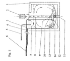
- Fig. 1 shows an insulated tank 1 that is adapted to contain a suspension of a combustible liquid mixed with carbon particles.
- an eddy current pump 9 driven by a shaft 8 that is connected to a motor 2 placed at the top of the tank.
- the pump 9, that is further shown in Fig. 2 has a branched outlet where one of the branches 13 is connected with a burner 6 via a pipe 3, while an other branch, or possibly two or more branches 14, is formed as a jet or a nozzle that is open towards its surroundings inside the tank.
- the pump is partly arranged to supply the burner 6 with suspension from the tank and partly arranged to circulate the suspension in the tank via the nozzle or the nozzles 14 to maintain the suspension of liquid and particles in the tank.
- the liquid level in the tank is monitored by a level monitor 7, that is not further shown in the Fig. 1.
- the tank is provided with one or more heating elements 10 to, if necessary, warm up the contents of the tank, if in case the tank contains a viscous, temperature dependent liquid.
- a suction pipe 5 is arranged in connection with the tank for evacuating possible vaporised components out of the tank.
- the eddy current pump 9 with fastening means and motor 2 is shown on an enlarged scale in Fig. 2.
- the pump comprises a pump housing 15 with an internal driven eddy current rotor 16, driven by a shaft 8.
- the rotor used in the pump may preferably be of the brand EGGER.
- the pump housing and thereby the pump is connected to an axle housing 17 with a flange connection 19.
- the purpose of the axle housing besides serving as an connection for the pump, is to provide a sealing of the shaft 8 and its bearings 20, 21, and in addition the pump bearing 22, against the surrounding liquid (suspension) in the tank.
- the bearings 21,22 is pressure lubricated by means of pressurised oil pipes 23 supplying oil from an oil reservoir or a pump 24 driven by a transmission belt 26 connected to the shaft 8.
- the axle housing 17 is at its top end attached to a removable hatch or cover 25 providing easy removal of the pump including its axle housing and driving motor, when performing maintenance or replacement operations.
- the axle is driven by the motor via direct connecting means 27.
- other connecting means such as transmission belts or gears, may alternatively be used within the scope of the invention.
Landscapes
- Engineering & Computer Science (AREA)
- Mechanical Engineering (AREA)
- General Engineering & Computer Science (AREA)
- Environmental & Geological Engineering (AREA)
- Chemical & Material Sciences (AREA)
- Combustion & Propulsion (AREA)
- Water Supply & Treatment (AREA)
- Feeding And Controlling Fuel (AREA)
- Structures Of Non-Positive Displacement Pumps (AREA)
- Physical Or Chemical Processes And Apparatus (AREA)
Description
- The present invention relates to equipment for the combustion of a suspension of a combustible liquid that contains a large amount of combustible material as solids in particle shape, for instance carbon particles. The equipment comprises a tank, a burner unit and a pipe for fluid transport, said pipe being arranged between the burner and an injection- or a feed pump located inside the tank.
- In Norwegian patent No. 171127, that is owned by the applicant, it is described an equipment of the type as mentioned above, comprising a pump of the displacement type, i.e. a ordinary gear pump. When using this type of pump, it is experienced that it operate in a satisfactory manner when combusting viscous liquids as tar from filters with small amounts of particles. However, when pumping suspensions with a larger content of carbon particles, pumps of this type are rapidly worn out, and have to be replaced. Another problem related to this known technique is that particles contained in the liquid precipitate and settle at the bottom of the tank, that may cause clogging at the pump inlet.
- It is an object of the present invention to provide a technical solution where the above mentioned problems are eliminated or substantially avoided. Thus, the invention represents a solution where the problems related to particle precipitation are avoided, and further the problem with excessive pump wear is substantially reduced.
- EP-A-0 466 167 discloses an apparatus for pumping fibre suspensions of the pulp and paper industry. The pump comprises at least two outlets, at least one of the outlets being preferably provided with a means for regulating the flow through the outlet. The outlets may have different diameters, where the ducts connected with the outletsreceive pulp from the pump at different pressures. The pump is arranged outside a vessel, where one outlet duct may return pulp back to the vessel for keeping the bottom level in said vessel moving to prevent the solids of the pulp from accumulating at the bottom of the vessel.
- The pump of the present invention differs from the pump in this reference as the present pump is arranged inside the tank and has a vertical rotation axis. These features, among others, will contribute to proper stirring and even particle distribution in the fluid pumped to the burner.
- In carbon plants around the world, for instance plants that produce carbon bodies for the aluminium industry, there is a large excess of carbon dust. This is generally carbon dust with a particle size less than 100 µm. Carbon dust of this type is today deposited, and represents in this manner a loss for the companies that "produce" the dust.
- When using the combustion equipment according to the present invention, the carbon dust may be combusted when mixing it with for instance waste oil. Tests have shown that it is possible to mix up to 50% (weight) coke dust in the oil, and having a quantity of energy corresponding to 36000 kJ/kg (10kWh/kg), the use of carbon dust for combustion purposes represents a substantial saving in energy costs per year. Besides, the use of carbon dust for combustion purposes will, in addition, lead to a reduction in the amount of dust to be deposited and correspondingly a reduced demand for waste depositing areas, thus having good environmental effects.
- The invention will now be further described by means of examples and with reference to the drawings where:
- Fig. 1
- shows a principal sketch of the equipment according to the invention, and
- Fig. 2
- shows on an enlarged scale an eddy current pump as shown in Fig. 1
- More precisely, Fig. 1 shows an
insulated tank 1 that is adapted to contain a suspension of a combustible liquid mixed with carbon particles. At the interior of the tank there is arranged an eddycurrent pump 9 driven by ashaft 8 that is connected to amotor 2 placed at the top of the tank. Thepump 9, that is further shown in Fig. 2, has a branched outlet where one of thebranches 13 is connected with aburner 6 via apipe 3, while an other branch, or possibly two ormore branches 14, is formed as a jet or a nozzle that is open towards its surroundings inside the tank. In this manner the pump is partly arranged to supply theburner 6 with suspension from the tank and partly arranged to circulate the suspension in the tank via the nozzle or thenozzles 14 to maintain the suspension of liquid and particles in the tank. The liquid level in the tank is monitored by alevel monitor 7, that is not further shown in the Fig. 1.
Moreover, the tank is provided with one ormore heating elements 10 to, if necessary, warm up the contents of the tank, if in case the tank contains a viscous, temperature dependent liquid. In addition, asuction pipe 5 is arranged in connection with the tank for evacuating possible vaporised components out of the tank. - The eddy
current pump 9 with fastening means andmotor 2 is shown on an enlarged scale in Fig. 2.
The pump comprises apump housing 15 with an internal driven eddycurrent rotor 16, driven by ashaft 8. The rotor used in the pump may preferably be of the brand EGGER. - The pump housing and thereby the pump is connected to an
axle housing 17 with aflange connection 19. The purpose of the axle housing, besides serving as an connection for the pump, is to provide a sealing of theshaft 8 and itsbearings bearings oil pipes 23 supplying oil from an oil reservoir or apump 24 driven by atransmission belt 26 connected to theshaft 8. - The
axle housing 17 is at its top end attached to a removable hatch or cover 25 providing easy removal of the pump including its axle housing and driving motor, when performing maintenance or replacement operations. - In the illustrated embodiment, the axle is driven by the motor via direct connecting means 27. Thus, it should be understood that other connecting means, such as transmission belts or gears, may alternatively be used within the scope of the invention.
Claims (1)
- Equipment for the combustion of a suspension of a combustible liquid and combustible solids in particle shape, for instance carbon particles, comprising a tank (1), a burner unit (6) and a pipe (3) for transporting the suspension, said pipe having one end connected to the burner unit (6), and having its other end protruding into the tank where it is connected to a pump (9) arranged inside the tank,
characterized in that
the pump (9) is an eddy current pump with its axis of rotation arranged vertically and further being provided with a branched outlet (12), where one of the outlet branches (13) is connected to the pipe (3), while the other branch or branches (14) is formed as a nozzle or a jet with its outlet directed into the tank, thus serving to stir the suspension in the tank.
Applications Claiming Priority (2)
| Application Number | Priority Date | Filing Date | Title |
|---|---|---|---|
| NO944107A NO300436B1 (en) | 1994-10-28 | 1994-10-28 | Device for equipment for combustion of liquids with high particle content |
| NO944107 | 1994-10-28 |
Publications (3)
| Publication Number | Publication Date |
|---|---|
| EP0709623A2 EP0709623A2 (en) | 1996-05-01 |
| EP0709623A3 EP0709623A3 (en) | 1997-11-12 |
| EP0709623B1 true EP0709623B1 (en) | 2001-06-13 |
Family
ID=19897569
Family Applications (1)
| Application Number | Title | Priority Date | Filing Date |
|---|---|---|---|
| EP95115763A Expired - Lifetime EP0709623B1 (en) | 1994-10-28 | 1995-10-06 | Equipment for the combustion of fluids with high particle content |
Country Status (11)
| Country | Link |
|---|---|
| US (1) | US5709160A (en) |
| EP (1) | EP0709623B1 (en) |
| AU (1) | AU695228B2 (en) |
| BR (1) | BR9504597A (en) |
| CA (1) | CA2160446A1 (en) |
| DE (1) | DE69521265T2 (en) |
| EG (1) | EG21381A (en) |
| NO (1) | NO300436B1 (en) |
| NZ (1) | NZ280174A (en) |
| RU (1) | RU2142600C1 (en) |
| ZA (1) | ZA958796B (en) |
Families Citing this family (1)
| Publication number | Priority date | Publication date | Assignee | Title |
|---|---|---|---|---|
| US9453519B2 (en) * | 2013-07-05 | 2016-09-27 | Kanzaki Kokyukoki Mfg. Co., Ltd. | Transaxle |
Family Cites Families (9)
| Publication number | Priority date | Publication date | Assignee | Title |
|---|---|---|---|---|
| US2890659A (en) * | 1955-05-27 | 1959-06-16 | Haentjens Otto | Slurry pump |
| US3357375A (en) * | 1965-08-17 | 1967-12-12 | Prenco Mfg Company | Incineration of industrial waste, and apparatus |
| FR2093106A5 (en) * | 1970-06-02 | 1972-01-28 | Elf Union | |
| US4534654A (en) * | 1983-07-27 | 1985-08-13 | A. J. Sackett & Sons Co. | High-speed fluid blender |
| IT1177231B (en) * | 1984-11-16 | 1987-08-26 | Alberto Cipelletti | AGITATION AND HOMOGENIZATION DEVICE FOR FOOD MIXTURES |
| US4599954A (en) * | 1985-02-22 | 1986-07-15 | Williams Patent Crusher And Pulverizer Company | Sewage sludge disposal process and apparatus therefor |
| FR2600755B1 (en) * | 1986-06-26 | 1990-12-21 | Pivernat Thierry | FUEL-WATER EMULSION BURNER SUPPLY SYSTEM |
| US5228829A (en) * | 1986-08-20 | 1993-07-20 | A. Ahlstrom Corporation | Method and apparatus for dividing flow of high-consistency fiber suspension |
| NO171127C (en) * | 1990-08-31 | 1993-01-27 | Norsk Hydro As | DEVICE FOR EQUIPMENT FOR COMBUSTION OF VISIBLE LIQUIDS |
-
1994
- 1994-10-28 NO NO944107A patent/NO300436B1/en not_active IP Right Cessation
-
1995
- 1995-10-05 NZ NZ280174A patent/NZ280174A/en unknown
- 1995-10-06 EP EP95115763A patent/EP0709623B1/en not_active Expired - Lifetime
- 1995-10-06 DE DE69521265T patent/DE69521265T2/en not_active Expired - Fee Related
- 1995-10-09 AU AU33097/95A patent/AU695228B2/en not_active Ceased
- 1995-10-12 CA CA002160446A patent/CA2160446A1/en not_active Abandoned
- 1995-10-18 ZA ZA958796A patent/ZA958796B/en unknown
- 1995-10-25 EG EG89495A patent/EG21381A/en active
- 1995-10-26 RU RU95118408/06A patent/RU2142600C1/en not_active IP Right Cessation
- 1995-10-27 BR BR9504597A patent/BR9504597A/en not_active IP Right Cessation
- 1995-10-30 US US08/550,293 patent/US5709160A/en not_active Expired - Fee Related
Also Published As
| Publication number | Publication date |
|---|---|
| AU3309795A (en) | 1996-05-09 |
| EG21381A (en) | 2001-09-30 |
| NO300436B1 (en) | 1997-05-26 |
| DE69521265T2 (en) | 2002-05-16 |
| EP0709623A3 (en) | 1997-11-12 |
| AU695228B2 (en) | 1998-08-06 |
| BR9504597A (en) | 1997-05-27 |
| CA2160446A1 (en) | 1996-04-29 |
| NZ280174A (en) | 1998-02-26 |
| US5709160A (en) | 1998-01-20 |
| NO944107D0 (en) | 1994-10-28 |
| RU2142600C1 (en) | 1999-12-10 |
| EP0709623A2 (en) | 1996-05-01 |
| DE69521265D1 (en) | 2001-07-19 |
| NO944107L (en) | 1996-04-29 |
| ZA958796B (en) | 1996-05-09 |
Similar Documents
| Publication | Publication Date | Title |
|---|---|---|
| US6213929B1 (en) | Motor driven centrifugal filter | |
| KR100243889B1 (en) | Lubricator for tandem axle | |
| US5843284A (en) | Two-stage oil bypass filter device | |
| US5353760A (en) | Multiple engine oil and fuel system | |
| AU668061B1 (en) | Method for preventing accumulation of sludge in a coal water mixture storage tank | |
| CA1081132A (en) | Waste oil recovery unit | |
| US5476073A (en) | Diesel engine waste oil recycling system | |
| EP0709623B1 (en) | Equipment for the combustion of fluids with high particle content | |
| MXPA04010540A (en) | Agitator drive. | |
| US4683985A (en) | Lubrication system for a vertical gear unit | |
| US10082149B2 (en) | Pump, separation device for a pump, and rotor shaft for a pump | |
| US5507307A (en) | Method and apparatus for recycling waste lubrication oil for reuse as fuel oil | |
| US5538462A (en) | Lapping compound supply system for a gear finishing machine | |
| DE2254082C3 (en) | Process for lubricating the gearbox of a gas turbine and gas turbine for carrying out the process | |
| US5715912A (en) | Integrated lubrication system using solid oil and oil mist with a demister | |
| US20100193295A1 (en) | Bearing lubrication | |
| CA2985133A1 (en) | A drive module and its uses, a flotation plant and a method of changing of the drive module | |
| US5044895A (en) | Oil supply device for a rotary machine | |
| CA1302783C (en) | Pump | |
| CN2861561Y (en) | Submersible oil pump | |
| CN208686594U (en) | Electric lime-ash liquid pump under New | |
| RU2773931C1 (en) | Three-coordinate screw mixing device | |
| CN211118667U (en) | Efficient independent lubricating equipment | |
| CN207342976U (en) | A kind of high filler bi-component resin slurry grinding is dispersed with stirring spraying integrated apparatus | |
| NZ239624A (en) | Equipment for burning tar including a displacement pump. (51) f23g7/00; |
Legal Events
| Date | Code | Title | Description |
|---|---|---|---|
| PUAI | Public reference made under article 153(3) epc to a published international application that has entered the european phase |
Free format text: ORIGINAL CODE: 0009012 |
|
| AK | Designated contracting states |
Kind code of ref document: A2 Designated state(s): DE FR GB IT NL |
|
| RAP1 | Party data changed (applicant data changed or rights of an application transferred) |
Owner name: NORSK HYDRO ASA |
|
| PUAL | Search report despatched |
Free format text: ORIGINAL CODE: 0009013 |
|
| AK | Designated contracting states |
Kind code of ref document: A3 Designated state(s): DE FR GB IT NL |
|
| 17P | Request for examination filed |
Effective date: 19980126 |
|
| 17Q | First examination report despatched |
Effective date: 19991118 |
|
| GRAG | Despatch of communication of intention to grant |
Free format text: ORIGINAL CODE: EPIDOS AGRA |
|
| GRAG | Despatch of communication of intention to grant |
Free format text: ORIGINAL CODE: EPIDOS AGRA |
|
| GRAH | Despatch of communication of intention to grant a patent |
Free format text: ORIGINAL CODE: EPIDOS IGRA |
|
| GRAH | Despatch of communication of intention to grant a patent |
Free format text: ORIGINAL CODE: EPIDOS IGRA |
|
| GRAA | (expected) grant |
Free format text: ORIGINAL CODE: 0009210 |
|
| AK | Designated contracting states |
Kind code of ref document: B1 Designated state(s): DE FR GB IT NL |
|
| REF | Corresponds to: |
Ref document number: 69521265 Country of ref document: DE Date of ref document: 20010719 |
|
| ITF | It: translation for a ep patent filed | ||
| ET | Fr: translation filed | ||
| REG | Reference to a national code |
Ref country code: GB Ref legal event code: IF02 |
|
| PLBE | No opposition filed within time limit |
Free format text: ORIGINAL CODE: 0009261 |
|
| STAA | Information on the status of an ep patent application or granted ep patent |
Free format text: STATUS: NO OPPOSITION FILED WITHIN TIME LIMIT |
|
| 26N | No opposition filed | ||
| PGFP | Annual fee paid to national office [announced via postgrant information from national office to epo] |
Ref country code: GB Payment date: 20031001 Year of fee payment: 9 |
|
| PGFP | Annual fee paid to national office [announced via postgrant information from national office to epo] |
Ref country code: FR Payment date: 20031003 Year of fee payment: 9 |
|
| PGFP | Annual fee paid to national office [announced via postgrant information from national office to epo] |
Ref country code: NL Payment date: 20031008 Year of fee payment: 9 |
|
| PGFP | Annual fee paid to national office [announced via postgrant information from national office to epo] |
Ref country code: DE Payment date: 20031016 Year of fee payment: 9 |
|
| PG25 | Lapsed in a contracting state [announced via postgrant information from national office to epo] |
Ref country code: GB Free format text: LAPSE BECAUSE OF NON-PAYMENT OF DUE FEES Effective date: 20041006 |
|
| PG25 | Lapsed in a contracting state [announced via postgrant information from national office to epo] |
Ref country code: NL Free format text: LAPSE BECAUSE OF NON-PAYMENT OF DUE FEES Effective date: 20050501 |
|
| PG25 | Lapsed in a contracting state [announced via postgrant information from national office to epo] |
Ref country code: DE Free format text: LAPSE BECAUSE OF NON-PAYMENT OF DUE FEES Effective date: 20050503 |
|
| GBPC | Gb: european patent ceased through non-payment of renewal fee |
Effective date: 20041006 |
|
| PG25 | Lapsed in a contracting state [announced via postgrant information from national office to epo] |
Ref country code: FR Free format text: LAPSE BECAUSE OF NON-PAYMENT OF DUE FEES Effective date: 20050630 |
|
| NLV4 | Nl: lapsed or anulled due to non-payment of the annual fee |
Effective date: 20050501 |
|
| REG | Reference to a national code |
Ref country code: FR Ref legal event code: ST |
|
| PG25 | Lapsed in a contracting state [announced via postgrant information from national office to epo] |
Ref country code: IT Free format text: LAPSE BECAUSE OF NON-PAYMENT OF DUE FEES;WARNING: LAPSES OF ITALIAN PATENTS WITH EFFECTIVE DATE BEFORE 2007 MAY HAVE OCCURRED AT ANY TIME BEFORE 2007. THE CORRECT EFFECTIVE DATE MAY BE DIFFERENT FROM THE ONE RECORDED. Effective date: 20051006 |