EP0709628B1 - Système thermochimique et son utilisation - Google Patents
Système thermochimique et son utilisation Download PDFInfo
- Publication number
- EP0709628B1 EP0709628B1 EP95402392A EP95402392A EP0709628B1 EP 0709628 B1 EP0709628 B1 EP 0709628B1 EP 95402392 A EP95402392 A EP 95402392A EP 95402392 A EP95402392 A EP 95402392A EP 0709628 B1 EP0709628 B1 EP 0709628B1
- Authority
- EP
- European Patent Office
- Prior art keywords
- reactor
- gas
- heat
- salt
- temperature
- Prior art date
- Legal status (The legal status is an assumption and is not a legal conclusion. Google has not performed a legal analysis and makes no representation as to the accuracy of the status listed.)
- Expired - Lifetime
Links
Images


Classifications
-
- C—CHEMISTRY; METALLURGY
- C09—DYES; PAINTS; POLISHES; NATURAL RESINS; ADHESIVES; COMPOSITIONS NOT OTHERWISE PROVIDED FOR; APPLICATIONS OF MATERIALS NOT OTHERWISE PROVIDED FOR
- C09K—MATERIALS FOR MISCELLANEOUS APPLICATIONS, NOT PROVIDED FOR ELSEWHERE
- C09K5/00—Heat-transfer, heat-exchange or heat-storage materials, e.g. refrigerants; Materials for the production of heat or cold by chemical reactions other than by combustion
- C09K5/16—Materials undergoing chemical reactions when used
-
- F—MECHANICAL ENGINEERING; LIGHTING; HEATING; WEAPONS; BLASTING
- F25—REFRIGERATION OR COOLING; COMBINED HEATING AND REFRIGERATION SYSTEMS; HEAT PUMP SYSTEMS; MANUFACTURE OR STORAGE OF ICE; LIQUEFACTION SOLIDIFICATION OF GASES
- F25B—REFRIGERATION MACHINES, PLANTS OR SYSTEMS; COMBINED HEATING AND REFRIGERATION SYSTEMS; HEAT PUMP SYSTEMS
- F25B17/00—Sorption machines, plants or systems, operating intermittently, e.g. absorption or adsorption type
- F25B17/08—Sorption machines, plants or systems, operating intermittently, e.g. absorption or adsorption type the absorbent or adsorbent being a solid, e.g. salt
- F25B17/083—Sorption machines, plants or systems, operating intermittently, e.g. absorption or adsorption type the absorbent or adsorbent being a solid, e.g. salt with two or more boiler-sorbers operating alternately
-
- F—MECHANICAL ENGINEERING; LIGHTING; HEATING; WEAPONS; BLASTING
- F28—HEAT EXCHANGE IN GENERAL
- F28D—HEAT-EXCHANGE APPARATUS, NOT PROVIDED FOR IN ANOTHER SUBCLASS, IN WHICH THE HEAT-EXCHANGE MEDIA DO NOT COME INTO DIRECT CONTACT
- F28D20/00—Heat storage plants or apparatus in general; Regenerative heat-exchange apparatus not covered by groups F28D17/00 or F28D19/00
- F28D20/003—Heat storage plants or apparatus in general; Regenerative heat-exchange apparatus not covered by groups F28D17/00 or F28D19/00 using thermochemical reactions
-
- F—MECHANICAL ENGINEERING; LIGHTING; HEATING; WEAPONS; BLASTING
- F28—HEAT EXCHANGE IN GENERAL
- F28F—DETAILS OF HEAT-EXCHANGE AND HEAT-TRANSFER APPARATUS, OF GENERAL APPLICATION
- F28F21/00—Constructions of heat-exchange apparatus characterised by the selection of particular materials
- F28F21/02—Constructions of heat-exchange apparatus characterised by the selection of particular materials of carbon, e.g. graphite
-
- Y—GENERAL TAGGING OF NEW TECHNOLOGICAL DEVELOPMENTS; GENERAL TAGGING OF CROSS-SECTIONAL TECHNOLOGIES SPANNING OVER SEVERAL SECTIONS OF THE IPC; TECHNICAL SUBJECTS COVERED BY FORMER USPC CROSS-REFERENCE ART COLLECTIONS [XRACs] AND DIGESTS
- Y02—TECHNOLOGIES OR APPLICATIONS FOR MITIGATION OR ADAPTATION AGAINST CLIMATE CHANGE
- Y02E—REDUCTION OF GREENHOUSE GAS [GHG] EMISSIONS, RELATED TO ENERGY GENERATION, TRANSMISSION OR DISTRIBUTION
- Y02E60/00—Enabling technologies; Technologies with a potential or indirect contribution to GHG emissions mitigation
- Y02E60/14—Thermal energy storage
Definitions
- the present invention relates to a system thermochemical as well as the use of such a system thermochemical.
- reaction is exothermic in direction 1, which means that in this sense it produces heat, and endothermic in direction 2, i.e. in this direction it produces cold.
- Such a system allows energy storage under chemical form and has areas of application varied.
- the system is called "heat pump chemical”.
- Such a system also allows the production, from a heat source at temperature T's, of heat at temperature T'u such that: You> You
- thermo chemical transformer the system is called "thermo chemical transformer"
- the use of heat or cold produced is simultaneous with energy consumption at high temperature (Ts, T's, T "s) or delayed over time (storage effect).
- thermochemicals include an active agent, typically a salt, mixed with an inert binder which allows good transfer of mass and heat.
- an active agent typically a salt
- inert binder which allows good transfer of mass and heat.
- binder expanded graphite possibly recompressed.
- EP-A-0 129 473 and EP-A 0 477 343 describe reagents consisting of a single active agent and of expanded graphite. These reagents are used to put using reversible reactions with a gas, for example example, ammonia.
- EP-A-0 129 473 describes in particular the possibility of using a mixture of these active agents for form a reagent.
- Thermochemical systems using this type of reaction include reaction chambers, connected either together in pairs or to an evaporator and a condenser, each reaction chamber containing a mixture of a single salt and expanded graphite.
- This kind of system is described in document EP-A 0 250 368.
- the document FR-A- 2 687 462 describes a thermochemical device which includes reaction chambers which are provided each of reagent blocks arranged one next to the other, each block being impregnated with a different salt. Use of this arrangement of blocks considerably improves the performance of the device, more commonly called "COP".
- reaction characteristics of a block of reactive, formed from expanded graphite, recompressed and impregnated of a salt are a function of the density of the block, of the salt used and its concentration.
- the use of a single salt to impregnate graphite results in a range of characteristics which is necessarily limited.
- the present invention relates to a system thermochemical.
- thermochemical system intended to produce cold and / or heat by solid-gas chemical reaction
- a thermochemical system intended to produce cold and / or heat by solid-gas chemical reaction
- a first reactor containing a reagent formed by a support tablet and an active agent vis-à-vis a gas, the active agent comprising at least two salts distributed throughout the compressed support, the reactor being in communication, in a first operating phase with a condenser for the gas, the system further comprising two evaporators, the reactor being intended to be put in communication selectively, in a second operational phase, with one either of the evaporators to produce cold for two temperature levels.
- the present invention also relates to the use of a thermochemical system in order to be able produce at least two cold and / or heat temperature levels, or at least two levels of power.
- thermochemical system comprising a reactor consisting of a compressed support and an active agent vis-à-vis a gas, the reactor being in communication, in a first operating phase with an enclosure intended for retain the gas, and in a second operating phase with an enclosure intended to release the gas, the active agent comprising at least two salts distributed throughout the compressed support, to produce cold and / or heat at least two temperature levels, or at least two power levels.
- reaction characteristics of a block of reactive, formed from recompressed and impregnated expanded graphite of a salt are a function of the density of the block, of the salt used and its concentration as well as the difference term to the balance imposed on it.
- the term difference to the equilibrium can be represented by the value of DTeq, difference between the equilibrium temperature of salt and the stress temperature imposed on the reagent via a exchanger by a heat transfer fluid.
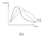
- Figure 1 are represented time-dependent power curves for reagent blocks operating under conditions thermodynamics given: pressure levels and identical stress temperature.
- the solid line is the reaction curve of a expanded density recompressed graphite block given, impregnated with salt A.
- the hatched line is the curve reaction of the same type of block but impregnated with a salt B.
- the dotted line is the reaction curve of the same type of block impregnated with salts A and B in a fixed proportion.
- the curve A + B is essentially the result of curves A and B.
- thermochemical system Choosing an active agent to use in a reagent of thermochemical system depends on the application for which the system is intended for. The realization of a block of reagent containing two or more different salts allows to realize many applications which were not previously possible with reagents containing only one salt.
- active agent in the present context is meant a compound chosen from halides, pseudohalides, carbonates, sulfates, nitrates, oxides or metal hydrides.
- the gas capable of reacting with such reactive agents can be water, ammonia, CO 2 , SO 2 , SO 3 or H 2 .
- a block of recompressed expanded graphite having a density of between 0.02 and 0.8 is impregnated with a solution of six different salts, the thermodynamic characteristics of which are given below: Salt Balanced Enthalpy (Jmole -1) Entropy (Jmole -1 K -1 ) S1: CaCl2 (8/4) 41,000 230 S2: ZnCl2 (6/4) 45,000 230 S3: MnCl2 (6/2) 48,000 228 S4: FeCl2 (6/2) 52,000 228 S5: MgCl2 (6/2) 56,000 230 S6: NiCl2 (6/2) 59,000 228
- Figure 2 is a Clapeyron diagram including the equilibrium curves of the six salts used to impregnate the block in this example.
- the equilibrium curve between the gas and liquid phases of the gas used, which in example, is ammonia is also shown.
- thermochemical system intended to allow the use of this reagent is shown in the figures 4A, 4B, 4C and 4D.
- This system includes two speakers intended each contain a reagent block, the chambers will be hereinafter called reactors R1 and R2.
- the system includes, in addition, a condenser C and an evaporator E, a source of heat (not shown) intended to provide the high temperature Th.
- This heat source can include, for for example, a gas burner or an electrical resistance.
- the system is supplemented by a heat exchanger with air ambient which allows to cool, to a temperature Tm, a heat transfer fluid used in the system, and by a pump circulation of this fluid.
- FIG 4a is shown the system during the start of the operating cycle where the reactor R1 is at temperature level Th 'at the pressure of the evaporator P evap ; the reactor R2 is at Tm 'at the pressure of the condenser P cond.
- the circulation pump is running, the heat transfer fluid is heated by the source at Th and begins to heat the right of the reactor R2.
- the heat transfer fluid is cooled to Tm '. It then passes through the heat exchanger which allows it to be cooled from Tm 'to Tm.
- the heat transfer fluid enters the reactor R1 and begins to cool the left of the reactor R1.
- the heat transfer fluid is heated to the initial temperature of the reactor Th '.
- the fluid is then heated by the source at Th before being sent to R2.
- phase change test can be done on an output temperature level of R1, a level progress of the reactor or over a period.
- the next phase is engaged by reversing the direction of circulation of the heat transfer fluid.
- the reactors are isolated from the condenser and the evaporator.
- the heat transfer fluid heated to Th by the heat source Now begins to heat the reactor R1 from the right.
- the heat transfer fluid is cooled when passing through R1 up to a temperature close to Tm; the supplement of calories to be removed (if necessary) is obtained by the heat exchanger which sets the temperature Tm to the inlet of reactor R2.
- the heat transfer fluid then enters in reactor R2 from the left. It is warmed up during its crossing to a temperature close to Th.
- R1 is at pressure P evap
- R2 is at pressure P cond .
- the heat input to the reactor R1 causes the start of the desorption in the right part of the reactor (looking at the drawings). With the reactor isolated, the pressure increases throughout the reactor. The cooling of reactor R2 from the left causes the start of absorption. With the reactor isolated, the pressure drops throughout the reactor. The transition from Tm to Tm 'at the outlet of reactor R1, or from Th to Th' at the outlet of reactor R2 takes place quickly because it involves only sensible heat terms; the mixture is outside the reaction range for all of the salts.
- reactors are in the conditions shown in figure 4d.
- Figure 5A is a Clapeyron diagram comprising the equilibrium lines of the salts used, as well that the equilibrium line between the gas phases and liquid of the gas used which, in the example, is ammonia.
- FIGs 5B to 5F a system thermochemical comprising two reactors R and R ', each containing a reagent block containing the 6 illustrated salts on the Clapeyron diagram of Figure 5A.
- Each reactor has a heat transfer fluid circuit to provide or extract heat.
- the R and R 'reactors can be selectively linked to a evaporator E or to a condenser C by conduits appropriate.
- the initial state of the system is shown on the FIG. 5B, the operating conditions of the reactors R and R ' corresponding to points A and C respectively in the figure 5A.
- the heat transfer circuit provides the reactor R 'with heat at temperature Tn.
- the R reactor is cooled by its heat transfer circuit.
- the reactor R passes from point A at point B 'by being connected to condenser C from point B. At the same time, the reactor R 'passes from point C to the point By being connected to the evaporator E from point D.
- the two heat transfer circuits are connected during this step, the heat transfer fluid being circulated in order to transfer heat between reactors.
- Reactor R goes from point B 'to point C, heat being provided by the heat transfer circuit.
- the R 'reactor goes from point D to point A, heat being extracted via the heat transfer system exchanger associated.
- Reactor R goes from point C to point D 'by being connected to the evaporator E from point D, while the reactor R 'passes from point A to point B' in being connected, from point B, to condenser C. Both heat transfer circuits are connected during this stage, the heat transfer fluid being circulated in order to transfer heat between reactors.
- a single reactor R provided with a reagent containing two salts S 1 and S 2 , and adapted to be selectively connected to a condenser C or to one or the other of two evaporators E 1 , E 2 .
- the reactor R is first put in communication with the evaporator E 1 .
- the salts S1 and S2 have both decomposed at Th.
- the greater equilibrium difference between Tamb and the equilibrium line salt S2 has the effect that this salt reacts preferentially with the gas and imposes the level of temperature and pressure on the reactive mixture.
- the reactor When the pressure in the reactor reaches Pevap2, the reactor is placed in communication with the evaporator E2 and allows the production of cold at the temperature Tevap2.
- the valve V2 When the reaction between the salt S2 and the gas is complete, the valve V2 is closed and the valve V1 is open. This causes the pressure rise from Pévap2 to Pévapl.
- the salt S1 is then in synthesis condition and allows the production of cold by evaporation at a temperature Tévap1 higher than Tévap2. It is conceivable to use a reagent block impregnated with three or more salts, the system of use comprises an evaporator per salt used. Such a system would allow cold at several temperature levels.
Landscapes
- Engineering & Computer Science (AREA)
- Physics & Mathematics (AREA)
- Thermal Sciences (AREA)
- Chemical & Material Sciences (AREA)
- Mechanical Engineering (AREA)
- General Engineering & Computer Science (AREA)
- Chemical Kinetics & Catalysis (AREA)
- General Chemical & Material Sciences (AREA)
- Materials Engineering (AREA)
- Organic Chemistry (AREA)
- Combustion & Propulsion (AREA)
- Sorption Type Refrigeration Machines (AREA)
- Physical Or Chemical Processes And Apparatus (AREA)
- Organic Low-Molecular-Weight Compounds And Preparation Thereof (AREA)
- Saccharide Compounds (AREA)
- Coke Industry (AREA)
- Crystals, And After-Treatments Of Crystals (AREA)
- Hydrogen, Water And Hydrids (AREA)
- Ceramic Products (AREA)
- Investigating Or Analyzing Non-Biological Materials By The Use Of Chemical Means (AREA)
Description
- on utilise pour le fonctionnement du système lui-même, l'énergie thermique ; l'énergie électrique peut éventuellement n'être utilisée que pour la circulation des fluides caloporteurs,
- on utilise, comme "moteur chimique" une réaction
réversible entre un solide et un gaz du type :

- la figure 1 montre des courbes des caractéristiques réactionnelles de blocs de réactifs ;
- les figures 2 et 3 sont des diagrammes de Clapeyron ;
- les figures 4A,4B,4C et 4D sont des vues schématiques d'un système thermochimique permettant la mise en oeuvre du procédé selon l'invention ;
- la figure 5A est un diagramme de Clapeyron concernant un deuxième mode de réalisation de l'invention ;
- les figures 5B à 5F sont des vues schématiques d'un système thermochimique selon le deuxième mode de réalisation ;
- la figure 6 est un diagramme de Clapeyron concernant un troisième mode de réalisation ;
- la figure 7A est un diagramme de Clapeyron concernant un quatrième mode de réalisation de l'invention ; et
- la figure 7B est une vue schématique d'un système thermochimique selon le quatrième mode de réalisation.
| Sel | Equilibre | Enthalpie (Jmole-1) | Entropie (Jmole-1K-1) |
| S1: CaCl2 | (8/4) | 41 000 | 230 |
| S2: ZnCl2 | (6/4) | 45 000 | 230 |
| S3: MnCl2 | (6/2) | 48 000 | 228 |
| S4: FeCl2 | (6/2) | 52 000 | 228 |
| S5: MgCl2 | (6/2) | 56 000 | 230 |
| S6: NiCl2 | (6/2) | 59 000 | 228 |
- ρsi
- densité du sel i (kg m-3)
- Mmolsi
- masse molaire du sel i (kg mole-1)
- nsi
- coefficient stoechiométrique
- Δhsi
- enthalpie de réaction du sel Si Joules/Mole de gaz

- Nselsi
- mole de sel si par mètre cube de réacteur.
- de la droite vers la gauche pour le réacteur R2 ;
- de la gauche vers la droite pour le réacteur R1.
Claims (3)
- Utilisation d'un système thermochimique, comprenant un réacteur contenant un réactif formé d'un support comprimé et d'un agent actif vis-à-vis d'un gaz, le réacteur étant en communication, dans une première phase opératoire avec une enceinte destinée à retenir le gaz, et dans une deuxième phase opératoire avec une enceinte destinée à libérer le gaz, l'agent actif comprenant au moins deux sels répartis dans l'ensemble du support comprimé, pour produire du froid et/ou de la chaleur à au moins deux niveaux de température, ou à au moins deux niveaux de puissance.
- Utilisation selon la revendication 1 caractérisée en ce que dans le système utilisé, l'enceinte destinée à retenir le gaz et l'enceinte destinée à libérer le gaz sont constituées par un deuxième réacteur muni d'un réactif formé d'un support comprimé et d'au moins deux sels répartis dans l'ensemble du support comprimé.
- Système thermochimique, destiné à produire du froid et/ou de la chaleur par réaction chimique solide-gaz, comprenant un réacteur contenant un réactif formé d'un support comprimé et d'un agent actif vis-à-vis d'un gaz l'agent actif comprenant au moins deux sels répartis dans l'ensemble du support comprimé, le réacteur étant en communication, dans une première phase opératoire avec un condenseur pour le gaz, le système comprenant de plus deux évaporateurs, le réacteur étant destiné à être mis en communication sélectivement, dans une deuxième phase opératoire, avec l'un ou l'autre des évaporateurs afin de produire du froid à deux niveaux de température.
Applications Claiming Priority (2)
| Application Number | Priority Date | Filing Date | Title |
|---|---|---|---|
| FR9412938A FR2726282B1 (fr) | 1994-10-28 | 1994-10-28 | Reactif pour systemes thermochimiques et systeme thermochimique destine a utiliser un tel reactif |
| FR9412938 | 1994-10-28 |
Publications (2)
| Publication Number | Publication Date |
|---|---|
| EP0709628A1 EP0709628A1 (fr) | 1996-05-01 |
| EP0709628B1 true EP0709628B1 (fr) | 1998-12-09 |
Family
ID=9468326
Family Applications (1)
| Application Number | Title | Priority Date | Filing Date |
|---|---|---|---|
| EP95402392A Expired - Lifetime EP0709628B1 (fr) | 1994-10-28 | 1995-10-25 | Système thermochimique et son utilisation |
Country Status (9)
| Country | Link |
|---|---|
| US (1) | US5857346A (fr) |
| EP (1) | EP0709628B1 (fr) |
| JP (1) | JPH08233393A (fr) |
| KR (1) | KR960014289A (fr) |
| AT (1) | ATE174423T1 (fr) |
| CA (1) | CA2161578C (fr) |
| DE (1) | DE69506512T2 (fr) |
| ES (1) | ES2127492T3 (fr) |
| FR (1) | FR2726282B1 (fr) |
Families Citing this family (6)
| Publication number | Priority date | Publication date | Assignee | Title |
|---|---|---|---|---|
| FR2754740B1 (fr) * | 1996-10-21 | 1998-12-04 | Elf Aquitaine | Composite actif a structure feuilletee comprenant un agent actif sous forme de granules |
| FR2877426B1 (fr) * | 2004-11-04 | 2007-03-02 | Centre Nat Rech Scient Cnrse | Production de froid a tres basse temperature dans un dispositif thermochimique. |
| FR2877425B1 (fr) * | 2004-11-04 | 2007-01-19 | Techn Ice Sarl | Production de froid a tres basse temperature dans un dispositif thermochimique. |
| JP2009505828A (ja) * | 2005-08-31 | 2009-02-12 | コールドウェイ | 冷却および/または加熱機器用の熱化学反応装置 |
| JP4938323B2 (ja) * | 2006-03-14 | 2012-05-23 | 大阪瓦斯株式会社 | 熱交換型反応器の製造方法 |
| JP5761205B2 (ja) * | 2011-01-24 | 2015-08-12 | 富士通株式会社 | 吸着器及び吸着式ヒートポンプ |
Family Cites Families (17)
| Publication number | Priority date | Publication date | Assignee | Title |
|---|---|---|---|---|
| US1854589A (en) * | 1921-06-08 | 1932-04-19 | Frigidaire Corp | Gas or liquid storing material |
| FR613266A (fr) * | 1925-10-28 | 1926-11-13 | Silica Gel Corp | Procédé et appareil de réfrigération |
| US1892407A (en) * | 1929-10-10 | 1932-12-27 | Silica Gel Corp | Refrigeration system |
| US2496459A (en) * | 1942-06-06 | 1950-02-07 | Kleen Refrigerator Inc | Absorption or adsorption refrigeration |
| FR2547512B1 (fr) | 1983-06-15 | 1985-09-27 | Elf Aquitaine | Procede de mise en oeuvre de reactions gaz-solide |
| EP0250368B1 (fr) | 1986-06-20 | 1990-07-25 | GRETAG Aktiengesellschaft | Dispositif de copiage photographique |
| FR2620046B1 (fr) * | 1987-09-07 | 1989-12-01 | Elf Aquitaine | Procede de conduite d'une reaction d'absorption ou de desorption entre un gaz et un solide |
| FR2626496B1 (fr) * | 1988-01-29 | 1990-06-01 | Elf Aquitaine | Procede d'amelioration des caracteristiques d'absorption et de desorption d'un gaz par un milieu reactionnel |
| FR2642509B1 (fr) * | 1989-01-11 | 1995-01-27 | Elf Aquitaine | Dispositif pour la production du froid et/ou de la chaleur par reaction solide-gaz |
| US5186020A (en) * | 1991-01-23 | 1993-02-16 | Rocky Research | Portable cooler |
| US5271239A (en) * | 1990-11-13 | 1993-12-21 | Rocky Research | Cooling apparatus for electronic and computer components |
| US5441716A (en) * | 1989-03-08 | 1995-08-15 | Rocky Research | Method and apparatus for achieving high reaction rates |
| US5628205A (en) * | 1989-03-08 | 1997-05-13 | Rocky Research | Refrigerators/freezers incorporating solid-vapor sorption reactors capable of high reaction rates |
| US5263330A (en) * | 1989-07-07 | 1993-11-23 | Rocky Research | Discrete constant pressure system for staging solid-vapor compounds |
| ATE93748T1 (de) * | 1990-04-11 | 1993-09-15 | Elf Aquitaine | Aktive zusammensetzung und ihre verwendung als reaktionsmedium. |
| US5165247A (en) * | 1991-02-11 | 1992-11-24 | Rocky Research | Refrigerant recycling system |
| FR2687462A1 (fr) | 1992-02-14 | 1993-08-20 | Elf Aquitaine | Dispositif pour la production de froid et/ou de chaleur par reaction solide-gaz. |
-
1994
- 1994-10-28 FR FR9412938A patent/FR2726282B1/fr not_active Expired - Fee Related
-
1995
- 1995-10-25 AT AT95402392T patent/ATE174423T1/de not_active IP Right Cessation
- 1995-10-25 ES ES95402392T patent/ES2127492T3/es not_active Expired - Lifetime
- 1995-10-25 DE DE69506512T patent/DE69506512T2/de not_active Expired - Fee Related
- 1995-10-25 EP EP95402392A patent/EP0709628B1/fr not_active Expired - Lifetime
- 1995-10-27 CA CA002161578A patent/CA2161578C/fr not_active Expired - Fee Related
- 1995-10-28 KR KR1019950037835A patent/KR960014289A/ko not_active Ceased
- 1995-10-30 JP JP7282105A patent/JPH08233393A/ja active Pending
-
1997
- 1997-08-05 US US08/906,255 patent/US5857346A/en not_active Expired - Fee Related
Also Published As
| Publication number | Publication date |
|---|---|
| ES2127492T3 (es) | 1999-04-16 |
| EP0709628A1 (fr) | 1996-05-01 |
| JPH08233393A (ja) | 1996-09-13 |
| US5857346A (en) | 1999-01-12 |
| FR2726282A1 (fr) | 1996-05-03 |
| CA2161578C (fr) | 2000-02-15 |
| DE69506512D1 (de) | 1999-01-21 |
| KR960014289A (ko) | 1996-05-22 |
| FR2726282B1 (fr) | 1999-02-19 |
| ATE174423T1 (de) | 1998-12-15 |
| CA2161578A1 (fr) | 1996-04-29 |
| DE69506512T2 (de) | 1999-06-24 |
Similar Documents
| Publication | Publication Date | Title |
|---|---|---|
| EP3052773B1 (fr) | Système thermodynamique de stockage/production d'énergie électrique | |
| EP0622593B1 (fr) | Dispositif de réfrigération et de chauffage utilisant un sorbant solide | |
| EP0382586B1 (fr) | Dispositif pour la production du froid et/ou de la chaleur par réaction solide-gaz | |
| FR2855869A1 (fr) | Procede de refroidissement d'un produit, notamment pour la liquefaction d'un gaz, et dispositif pour sa mise en oeuvre | |
| EP0317597A1 (fr) | Procede pour produire du froid par reaction solide-gaz et dispositif s'y rapportant | |
| CA2028327C (fr) | Dispositifs et procede pour produire du froid et/ou de la chaleur par reaction solide-gaz geres par caloducs gravitationnels | |
| FR3014182A1 (fr) | Systeme avance de stockage d'energie par air comprime | |
| CA2161578C (fr) | Reactif pour systemes thermochimiques et systeme thermochimique destine a utiliser un tel reactif | |
| EP0580848B1 (fr) | Dispositif pour la production de froid et/ou de chaleur par reaction solide-gaz | |
| CA2207668C (fr) | Procede de gestion d'une reaction thermochimique ou d'une adsorption solide-gaz | |
| EP1809955B1 (fr) | Production de froid à très basse température dans un dispositif thermochimique. | |
| WO1997040328A1 (fr) | Dispositif thermochimique pour produire du froid et/ou de la chaleur | |
| EP3682176B1 (fr) | Procede de refrigeration d'un caisson isotherme jusqu'a une temperature cible et installation associee | |
| EP1529185B1 (fr) | Installation et procede pour la production de froid par un systeme a sorption renversable. | |
| FR3133430A1 (fr) | Pompe a chaleur a deux systemes de stockage et restitution d’energie thermique | |
| EP1523643B1 (fr) | Procede pour la production de froid, et installation pour la mise en oeuvre du procede. | |
| EP1608920B1 (fr) | Procede et dispositif pour la production de froid rapide et de forte puissance | |
| EP4490449B1 (fr) | Pompe a chaleur a deux systemes de stockage et restitution d'energie thermique | |
| EP0726432A2 (fr) | Echangeur de chaleur diphasique à température contrÔlée | |
| FR2499149A1 (fr) | Procede de transformation d'energie thermique en energie mecanique | |
| EP1809956A1 (fr) | Production de froid a tres basse temperature dans un dispositif thermochimique. |
Legal Events
| Date | Code | Title | Description |
|---|---|---|---|
| PUAI | Public reference made under article 153(3) epc to a published international application that has entered the european phase |
Free format text: ORIGINAL CODE: 0009012 |
|
| 17P | Request for examination filed |
Effective date: 19951031 |
|
| AK | Designated contracting states |
Kind code of ref document: A1 Designated state(s): AT BE CH DE DK ES FR GB GR IE IT LI LU NL PT SE |
|
| 17Q | First examination report despatched |
Effective date: 19971014 |
|
| GRAG | Despatch of communication of intention to grant |
Free format text: ORIGINAL CODE: EPIDOS AGRA |
|
| GRAG | Despatch of communication of intention to grant |
Free format text: ORIGINAL CODE: EPIDOS AGRA |
|
| GRAH | Despatch of communication of intention to grant a patent |
Free format text: ORIGINAL CODE: EPIDOS IGRA |
|
| GRAH | Despatch of communication of intention to grant a patent |
Free format text: ORIGINAL CODE: EPIDOS IGRA |
|
| GRAA | (expected) grant |
Free format text: ORIGINAL CODE: 0009210 |
|
| AK | Designated contracting states |
Kind code of ref document: B1 Designated state(s): AT BE CH DE DK ES FR GB GR IE IT LI LU NL PT SE |
|
| PG25 | Lapsed in a contracting state [announced via postgrant information from national office to epo] |
Ref country code: GR Free format text: LAPSE BECAUSE OF NON-PAYMENT OF DUE FEES Effective date: 19981209 |
|
| REF | Corresponds to: |
Ref document number: 174423 Country of ref document: AT Date of ref document: 19981215 Kind code of ref document: T |
|
| REG | Reference to a national code |
Ref country code: CH Ref legal event code: EP |
|
| REF | Corresponds to: |
Ref document number: 69506512 Country of ref document: DE Date of ref document: 19990121 |
|
| REG | Reference to a national code |
Ref country code: IE Ref legal event code: FG4D Free format text: FRENCH |
|
| ITF | It: translation for a ep patent filed | ||
| PG25 | Lapsed in a contracting state [announced via postgrant information from national office to epo] |
Ref country code: PT Free format text: LAPSE BECAUSE OF FAILURE TO SUBMIT A TRANSLATION OF THE DESCRIPTION OR TO PAY THE FEE WITHIN THE PRESCRIBED TIME-LIMIT Effective date: 19990309 Ref country code: DK Free format text: LAPSE BECAUSE OF FAILURE TO SUBMIT A TRANSLATION OF THE DESCRIPTION OR TO PAY THE FEE WITHIN THE PRESCRIBED TIME-LIMIT Effective date: 19990309 |
|
| GBT | Gb: translation of ep patent filed (gb section 77(6)(a)/1977) |
Effective date: 19990308 |
|
| REG | Reference to a national code |
Ref country code: ES Ref legal event code: FG2A Ref document number: 2127492 Country of ref document: ES Kind code of ref document: T3 |
|
| PG25 | Lapsed in a contracting state [announced via postgrant information from national office to epo] |
Ref country code: IE Free format text: LAPSE BECAUSE OF NON-PAYMENT OF DUE FEES Effective date: 19990820 |
|
| REG | Reference to a national code |
Ref country code: IE Ref legal event code: FD4D |
|
| PLBE | No opposition filed within time limit |
Free format text: ORIGINAL CODE: 0009261 |
|
| STAA | Information on the status of an ep patent application or granted ep patent |
Free format text: STATUS: NO OPPOSITION FILED WITHIN TIME LIMIT |
|
| PG25 | Lapsed in a contracting state [announced via postgrant information from national office to epo] |
Ref country code: LU Free format text: LAPSE BECAUSE OF NON-PAYMENT OF DUE FEES Effective date: 19991025 |
|
| PG25 | Lapsed in a contracting state [announced via postgrant information from national office to epo] |
Ref country code: LI Free format text: LAPSE BECAUSE OF NON-PAYMENT OF DUE FEES Effective date: 19991031 Ref country code: CH Free format text: LAPSE BECAUSE OF NON-PAYMENT OF DUE FEES Effective date: 19991031 Ref country code: BE Free format text: LAPSE BECAUSE OF NON-PAYMENT OF DUE FEES Effective date: 19991031 |
|
| 26N | No opposition filed | ||
| BERE | Be: lapsed |
Owner name: ELF AQUITAINE Effective date: 19991031 |
|
| REG | Reference to a national code |
Ref country code: CH Ref legal event code: PL |
|
| NLS | Nl: assignments of ep-patents |
Owner name: CENTRE NATIONAL DE LA RECHERCHE SCIENTIFIQUE |
|
| PGFP | Annual fee paid to national office [announced via postgrant information from national office to epo] |
Ref country code: AT Payment date: 20010925 Year of fee payment: 7 |
|
| PGFP | Annual fee paid to national office [announced via postgrant information from national office to epo] |
Ref country code: SE Payment date: 20010926 Year of fee payment: 7 |
|
| PGFP | Annual fee paid to national office [announced via postgrant information from national office to epo] |
Ref country code: NL Payment date: 20010927 Year of fee payment: 7 |
|
| PGFP | Annual fee paid to national office [announced via postgrant information from national office to epo] |
Ref country code: GB Payment date: 20010928 Year of fee payment: 7 |
|
| PGFP | Annual fee paid to national office [announced via postgrant information from national office to epo] |
Ref country code: DE Payment date: 20011004 Year of fee payment: 7 |
|
| PGFP | Annual fee paid to national office [announced via postgrant information from national office to epo] |
Ref country code: ES Payment date: 20011018 Year of fee payment: 7 |
|
| PGFP | Annual fee paid to national office [announced via postgrant information from national office to epo] |
Ref country code: FR Payment date: 20011026 Year of fee payment: 7 |
|
| REG | Reference to a national code |
Ref country code: GB Ref legal event code: IF02 |
|
| REG | Reference to a national code |
Ref country code: GB Ref legal event code: 732E |
|
| PG25 | Lapsed in a contracting state [announced via postgrant information from national office to epo] |
Ref country code: GB Free format text: LAPSE BECAUSE OF NON-PAYMENT OF DUE FEES Effective date: 20021025 Ref country code: AT Free format text: LAPSE BECAUSE OF NON-PAYMENT OF DUE FEES Effective date: 20021025 |
|
| PG25 | Lapsed in a contracting state [announced via postgrant information from national office to epo] |
Ref country code: SE Free format text: LAPSE BECAUSE OF NON-PAYMENT OF DUE FEES Effective date: 20021026 Ref country code: ES Free format text: LAPSE BECAUSE OF NON-PAYMENT OF DUE FEES Effective date: 20021026 |
|
| PG25 | Lapsed in a contracting state [announced via postgrant information from national office to epo] |
Ref country code: NL Free format text: LAPSE BECAUSE OF NON-PAYMENT OF DUE FEES Effective date: 20030501 Ref country code: DE Free format text: LAPSE BECAUSE OF NON-PAYMENT OF DUE FEES Effective date: 20030501 |
|
| EUG | Se: european patent has lapsed | ||
| GBPC | Gb: european patent ceased through non-payment of renewal fee | ||
| PG25 | Lapsed in a contracting state [announced via postgrant information from national office to epo] |
Ref country code: FR Free format text: LAPSE BECAUSE OF NON-PAYMENT OF DUE FEES Effective date: 20030630 |
|
| NLV4 | Nl: lapsed or anulled due to non-payment of the annual fee |
Effective date: 20030501 |
|
| REG | Reference to a national code |
Ref country code: FR Ref legal event code: ST |
|
| REG | Reference to a national code |
Ref country code: ES Ref legal event code: FD2A Effective date: 20031112 |
|
| PG25 | Lapsed in a contracting state [announced via postgrant information from national office to epo] |
Ref country code: IT Free format text: LAPSE BECAUSE OF NON-PAYMENT OF DUE FEES Effective date: 20051025 |