EP0709637A1 - Palier pour galet de guidage - Google Patents
Palier pour galet de guidage Download PDFInfo
- Publication number
- EP0709637A1 EP0709637A1 EP95113797A EP95113797A EP0709637A1 EP 0709637 A1 EP0709637 A1 EP 0709637A1 EP 95113797 A EP95113797 A EP 95113797A EP 95113797 A EP95113797 A EP 95113797A EP 0709637 A1 EP0709637 A1 EP 0709637A1
- Authority
- EP
- European Patent Office
- Prior art keywords
- roller
- roller bearing
- adjusting device
- axis
- bearing according
- Prior art date
- Legal status (The legal status is an assumption and is not a legal conclusion. Google has not performed a legal analysis and makes no representation as to the accuracy of the status listed.)
- Ceased
Links
- 238000006073 displacement reaction Methods 0.000 claims abstract description 5
- 230000002093 peripheral effect Effects 0.000 claims description 10
- 235000004443 Ricinus communis Nutrition 0.000 abstract 3
- 230000001419 dependent effect Effects 0.000 abstract 1
- 230000005540 biological transmission Effects 0.000 description 4
- 238000010276 construction Methods 0.000 description 1
- 238000005096 rolling process Methods 0.000 description 1
- 238000005494 tarnishing Methods 0.000 description 1
Images



Classifications
-
- F—MECHANICAL ENGINEERING; LIGHTING; HEATING; WEAPONS; BLASTING
- F27—FURNACES; KILNS; OVENS; RETORTS
- F27B—FURNACES, KILNS, OVENS OR RETORTS IN GENERAL; OPEN SINTERING OR LIKE APPARATUS
- F27B7/00—Rotary-drum furnaces, i.e. horizontal or slightly inclined
- F27B7/20—Details, accessories or equipment specially adapted for rotary-drum furnaces
- F27B7/22—Rotary drums; Supports therefor
-
- F—MECHANICAL ENGINEERING; LIGHTING; HEATING; WEAPONS; BLASTING
- F16—ENGINEERING ELEMENTS AND UNITS; GENERAL MEASURES FOR PRODUCING AND MAINTAINING EFFECTIVE FUNCTIONING OF MACHINES OR INSTALLATIONS; THERMAL INSULATION IN GENERAL
- F16C—SHAFTS; FLEXIBLE SHAFTS; ELEMENTS OR CRANKSHAFT MECHANISMS; ROTARY BODIES OTHER THAN GEARING ELEMENTS; BEARINGS
- F16C13/00—Rolls, drums, discs, or the like; Bearings or mountings therefor
- F16C13/02—Bearings
- F16C13/04—Bearings with only partial enclosure of the member to be borne; Bearings with local support at two or more points
-
- F—MECHANICAL ENGINEERING; LIGHTING; HEATING; WEAPONS; BLASTING
- F16—ENGINEERING ELEMENTS AND UNITS; GENERAL MEASURES FOR PRODUCING AND MAINTAINING EFFECTIVE FUNCTIONING OF MACHINES OR INSTALLATIONS; THERMAL INSULATION IN GENERAL
- F16C—SHAFTS; FLEXIBLE SHAFTS; ELEMENTS OR CRANKSHAFT MECHANISMS; ROTARY BODIES OTHER THAN GEARING ELEMENTS; BEARINGS
- F16C19/00—Bearings with rolling contact, for exclusively rotary movement
- F16C19/50—Other types of ball or roller bearings
- F16C19/507—Other types of ball or roller bearings with rolling elements journaled in one of the moving parts, e.g. stationary rollers to support a rotating part
Definitions
- the invention relates to a roller bearing for supporting a rotating tube rotating about an axis of rotation, comprising a roller rotating about a bearing axis, on the outer peripheral surface of which a peripheral running surface of the rotating tube is supported, the roller being supported with axial play.
- This type of storage has the disadvantage, however, that in certain operating states, for example when setting the bearing axles or laying the foundations, the rollers run against the end limits of the bearing and high axial forces occur between the outer peripheral surface of the roller and the peripheral bearing surface of the rotary tube and the transmission possibilities for reduce the circumferential torque accordingly.
- the invention is therefore based on the object of further developing the roller bearing according to the preamble of claim 1 in such a way that an optimal transmission of the circumferential torque is possible in any operating state.
- the roller bearing according to the invention is characterized in that a measuring device is provided for determining the respective axial position of the roller, which is connected via a control unit to an adjusting device which measures the angle between the bearing axis of the roller and the axis of rotation of the rotary tube as a function of the measured position the roller changed.
- the roller is preferably held approximately in a central position.
- FIG. 1 denotes a rotary tube which has relatively large diameter and length dimensions and is used in practice for various applications, such as, for example, in rotary tube furnaces, rotary tube coolers, rotary drum dryers and the like.
- the rotary tube has a rotary tube which rotates about a rotary axis 1a an essentially cylindrical casing which carries two races 2, 3 which are attached in a rotationally fixed manner with a suitable axial spacing from one another.
- the rotary tube 1 is rotatably supported or supported on two roller stations 4, 5.
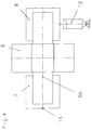
- Each roller station 4, 5 contains - as shown in FIG. 2 - two rollers 6 arranged symmetrically on both sides of the vertical longitudinal center plane 1b of the rotating tube 1.
- the peripheral running surface of the rotating tube formed by the ring 3 is supported on the outer peripheral surface (bearing surface) 6a of the rotating roller 6 1 rolling, whereby this circumferential running surface can also be formed directly on the cylindrical jacket of the rotary tube 1.
- the roller 6 is mounted on a bearing axis 6b, which their ends are freely rotatable in a first bearing 7 and a second bearing 8, which can be formed in the usual manner by roller or slide bearings.
- a support structure 9 which in turn is supported in a tiltable manner with respect to a stationary support surface.
- the bearing axis 6b is floating, i.e. with an axial play, stored in the two bearings 7, 8. As a result, the roller 6 can move back and forth about a central position 6c in the axial direction.
- a measuring device 10 is now provided according to the invention for determining the respective axial position of the roller 6.
- This measuring device 10 can be formed, for example, by a displacement sensor, which measures the change in position of the roller on both sides of the central position 6c.
- this measuring device it is also conceivable to implement this measuring device by means of two limit switches which are actuated before the respective end limits are reached.
- the measuring device 10 is connected to a control unit 11, via which an adjusting device 12 is controlled.
- the adjusting device 12 is, for example formed by a hydraulic cylinder which engages one of the two bearings, here on the second bearing 8.
- the adjusting device 12 could also be implemented, for example, by a lifting spindle drive.
- the first bearing 7 is supported on an adjusting spindle 13 in the embodiment shown in the drawing.
- An adjustment of the adjusting device 12 causes the entire bearing arrangement to rotate about a fulcrum 15 which lies on the longitudinal center plane containing the bearing axis 6b at the level of the adjusting spindle 13.
- the location of the fulcrum can essentially be chosen freely. It only has to be ensured that the angle between the bearing axis 6b of the roller 6 and the axis of rotation 1a of the rotary tube 1 can be changed by the adjusting device 12 as a function of the measured position of the roller. In Figure 3, the center line 6'b of the bearing axis of the roller is shown after such a change.
- the adjusting device acts approximately perpendicular to the vertical longitudinal center plane 1b of the rotary tube.
- the adjusting device 12 is acted upon by the control unit 11 with a corresponding control signal, so that the control cylinder either moves in the direction of the Longitudinal median plane of the rotary tube or away from it.
- the roller moves again in the direction of its central position.
- the adjustment device is useful actuated only when the roller has left a predetermined central area.
- the adjustment path of the adjustment device 12 can be measured by a further measuring device, for example a displacement sensor.
- the pivot point or the axis of rotation of the setting movement caused by the adjusting device 12 can be freely selected in a wide range.
- FIG. 4 shows a second exemplary embodiment of a roller bearing, in which this fulcrum or the axis of rotation 15 'is located in the axial direction before the first bearing 7.
- FIG. 5 shows a third, preferred embodiment of a roller bearing, in which the roller 6 with its first and second roller bearings 7, 8 is arranged on a base plate 14 or a so-called sole plate.
- the fulcrum of this base plate 14 is preferably in the longitudinal center plane of the roller bearing, which also contains the bearing axis 6b.
- the adjustment device 12 can engage at any suitable point on the base plate 14, either the adjustment device 12 being mounted in a suitable manner or the contact area between the adjustment device and the base plate being designed such that the pivoting movement of the base plate or bearing arrangement caused by the adjustment is taken into account and there is no tension between the adjusting device 12 and the base plate 14.
- the first condition is met by using a so-called tiltable roller station, as is also shown in FIG. 2.
- the second condition is realized particularly advantageously by the adjustment of the bearing arrangement according to the invention.
- the adjustment device according to the invention can be used both in the case of a tiltable and a rigid roller construction.
Landscapes
- Engineering & Computer Science (AREA)
- General Engineering & Computer Science (AREA)
- Mechanical Engineering (AREA)
- Rolls And Other Rotary Bodies (AREA)
- A Measuring Device Byusing Mechanical Method (AREA)
- Rolling Contact Bearings (AREA)
Applications Claiming Priority (2)
| Application Number | Priority Date | Filing Date | Title |
|---|---|---|---|
| DE4434116 | 1994-09-23 | ||
| DE4434116A DE4434116A1 (de) | 1994-09-23 | 1994-09-23 | Laufrollenlagerung |
Publications (1)
| Publication Number | Publication Date |
|---|---|
| EP0709637A1 true EP0709637A1 (fr) | 1996-05-01 |
Family
ID=6529068
Family Applications (1)
| Application Number | Title | Priority Date | Filing Date |
|---|---|---|---|
| EP95113797A Ceased EP0709637A1 (fr) | 1994-09-23 | 1995-09-01 | Palier pour galet de guidage |
Country Status (5)
| Country | Link |
|---|---|
| US (1) | US5613782A (fr) |
| EP (1) | EP0709637A1 (fr) |
| BR (1) | BR9504114A (fr) |
| DE (1) | DE4434116A1 (fr) |
| MX (1) | MX9504048A (fr) |
Families Citing this family (7)
| Publication number | Priority date | Publication date | Assignee | Title |
|---|---|---|---|---|
| DE19618662A1 (de) * | 1996-05-09 | 1997-11-13 | Indumont Ind Montage Gmbh | Verfahren und Einrichtung zur Ausrichtung von zu einem fluchtenden Rohrsystem wie Drehrohrofen zusammenzusetzenden Rohrschüssen |
| GB9828475D0 (en) * | 1998-12-24 | 1999-02-17 | British Aerospace | Load measurement |
| US6331691B1 (en) | 1999-09-20 | 2001-12-18 | Automated Laser Corporation | Precision guiding apparatus for laser marking system |
| CA2586951C (fr) * | 2004-11-12 | 2015-01-13 | Phillips Kiln Services Ltd. | Procede et appareil de surveillance de la poussee des supports |
| US7963701B2 (en) * | 2008-10-20 | 2011-06-21 | Phillips Kiln Services, Ltd. | System and method for setting roller skew |
| US8342493B2 (en) * | 2009-11-11 | 2013-01-01 | Koike Aronson, Inc. | Anti-drift turning roll system |
| CN105817945A (zh) * | 2016-05-26 | 2016-08-03 | 淮南市宜留机械科技有限公司 | 自调式滚轮架筒体类工件轴心调整装置 |
Citations (8)
| Publication number | Priority date | Publication date | Assignee | Title |
|---|---|---|---|---|
| GB225175A (en) * | 1923-11-24 | 1925-06-18 | Albin Berthold Helbig | Improvements in roller bearings or cradles for rotary drums |
| FR1235349A (fr) * | 1959-04-24 | 1960-07-08 | Dispositif de régulation et de contrôle des charges sur les coussinets et sur les butées axiales des paliers de galets supportant les appareils tournants sur bandage | |
| US3188155A (en) * | 1963-01-24 | 1965-06-08 | Allis Chalmers Mfg Co | Alignment indicating roller type support assembly |
| FR1557066A (fr) * | 1967-12-07 | 1969-02-14 | ||
| DE2801588A1 (de) * | 1978-01-14 | 1979-07-19 | Fink Gerdinand | Bewegliche, sich selbsttaetig nachrichtende laufrollenlagerung fuer drehrohroefen |
| EP0019136A1 (fr) * | 1979-05-09 | 1980-11-26 | F.L. Smidth & Co. A/S | Tambour rotatif comportant un anneau de roulement pour supporter le tambour rotatif sur un dispositif d'appui ajustable à galets |
| FR2537247A1 (fr) * | 1982-12-02 | 1984-06-08 | Ziffel Alain | Dispositif correcteur anti-vissage, pour un vireur de chaudronnerie |
| EP0567777A1 (fr) * | 1992-04-28 | 1993-11-03 | Krupp Polysius Ag | Palier à rouleaux basculant amovible |
Family Cites Families (11)
| Publication number | Priority date | Publication date | Assignee | Title |
|---|---|---|---|---|
| US3174810A (en) * | 1964-06-17 | 1965-03-23 | Allis Chalmers Mfg Co | Support for rotary kilns |
| US3561132A (en) * | 1969-09-10 | 1971-02-09 | Phillips Petroleum Co | Carbon black drying apparatus |
| SU1345037A1 (ru) * | 1986-01-02 | 1987-10-15 | Управление "Стромпусконаладка" | Устройство дл определени нагрузок на опорные ролики вращающейс печи |
| SU1377553A1 (ru) * | 1986-04-14 | 1988-02-28 | Львовский политехнический институт им.Ленинского комсомола | Устройство дл определени нагрузок на опоры вращающейс печи |
| SU1337634A1 (ru) * | 1986-04-28 | 1987-09-15 | Днепродзержинский Индустриальный Институт Им.М.И.Арсеничева | Опора вращающегос барабана |
| SU1502931A1 (ru) * | 1987-04-29 | 1989-08-23 | Львовский политехнический институт им.Ленинского комсомола | Устройство дл определени положени осей роликоопор |
| SU1659693A1 (ru) * | 1989-04-25 | 1991-06-30 | Львовский политехнический институт им.Ленинского комсомола | Способ диагностики оси преимущественно опорного ролика вращающейс печи и устройство дл его осуществлени |
| SU1719845A1 (ru) * | 1989-05-03 | 1992-03-15 | Львовский политехнический институт им.Ленинского комсомола | Устройство дл определени нагрузок на опорные ролики вращающейс печи |
| SU1719843A1 (ru) * | 1989-05-03 | 1992-03-15 | Львовский политехнический институт им.Ленинского комсомола | Устройство дл определени нагрузок на опоры вращающейс печи |
| SU1719846A1 (ru) * | 1989-06-20 | 1992-03-15 | Львовский политехнический институт им.Ленинского комсомола | Устройство дл контрол нагрузок на роликоопоре вращающейс печи |
| US5429440A (en) * | 1994-06-28 | 1995-07-04 | Svedala Industries, Inc. | Mechanism for adjusting the position of supports for large rotating apparatus |
-
1994
- 1994-09-23 DE DE4434116A patent/DE4434116A1/de not_active Withdrawn
-
1995
- 1995-09-01 EP EP95113797A patent/EP0709637A1/fr not_active Ceased
- 1995-09-08 US US08/525,309 patent/US5613782A/en not_active Expired - Fee Related
- 1995-09-21 BR BR9504114A patent/BR9504114A/pt not_active IP Right Cessation
- 1995-09-21 MX MX9504048A patent/MX9504048A/es unknown
Patent Citations (8)
| Publication number | Priority date | Publication date | Assignee | Title |
|---|---|---|---|---|
| GB225175A (en) * | 1923-11-24 | 1925-06-18 | Albin Berthold Helbig | Improvements in roller bearings or cradles for rotary drums |
| FR1235349A (fr) * | 1959-04-24 | 1960-07-08 | Dispositif de régulation et de contrôle des charges sur les coussinets et sur les butées axiales des paliers de galets supportant les appareils tournants sur bandage | |
| US3188155A (en) * | 1963-01-24 | 1965-06-08 | Allis Chalmers Mfg Co | Alignment indicating roller type support assembly |
| FR1557066A (fr) * | 1967-12-07 | 1969-02-14 | ||
| DE2801588A1 (de) * | 1978-01-14 | 1979-07-19 | Fink Gerdinand | Bewegliche, sich selbsttaetig nachrichtende laufrollenlagerung fuer drehrohroefen |
| EP0019136A1 (fr) * | 1979-05-09 | 1980-11-26 | F.L. Smidth & Co. A/S | Tambour rotatif comportant un anneau de roulement pour supporter le tambour rotatif sur un dispositif d'appui ajustable à galets |
| FR2537247A1 (fr) * | 1982-12-02 | 1984-06-08 | Ziffel Alain | Dispositif correcteur anti-vissage, pour un vireur de chaudronnerie |
| EP0567777A1 (fr) * | 1992-04-28 | 1993-11-03 | Krupp Polysius Ag | Palier à rouleaux basculant amovible |
Also Published As
| Publication number | Publication date |
|---|---|
| MX9504048A (es) | 1997-05-31 |
| BR9504114A (pt) | 1996-07-30 |
| DE4434116A1 (de) | 1996-03-28 |
| US5613782A (en) | 1997-03-25 |
Similar Documents
| Publication | Publication Date | Title |
|---|---|---|
| DE2638744C2 (fr) | ||
| EP1266137B1 (fr) | Palier pour une pale de rotor reglable d'une eolienne | |
| EP0019136B1 (fr) | Tambour rotatif comportant un anneau de roulement pour supporter le tambour rotatif sur un dispositif d'appui ajustable à galets | |
| DE4201906C2 (de) | Vorrichtung zum Lenken eines lenkbaren Rades durch Drehen eines Lenkrads | |
| DE3521055C2 (de) | Vorschubvorrichtung | |
| DE3112543C2 (de) | Kupplung zur Verbindung zweier umlaufender Wellen | |
| DE3801728C2 (de) | Rollenmühle | |
| EP0844976B1 (fr) | Dispositif servant au pivotement d'un rouleau pour une bande en mouvement | |
| DE69838504T2 (de) | Biegbare rolle für bandförmiges material | |
| WO2023227157A1 (fr) | Agencements de direction pour un véhicule et véhicule ayant une colonne de direction et un agencement de direction | |
| EP0570696B1 (fr) | Tambour rotatif | |
| DE2736581A1 (de) | Reibgetriebe | |
| EP2542849B1 (fr) | Entraînement pour un tambour rotatif | |
| DE19621585B4 (de) | Anordnung beim Antrieb einer Breitstreckwalze | |
| DE3426954C2 (de) | Übertragungsgelenk | |
| DE1575381A1 (de) | Lagerung und Antrieb fuer eine Walze mit steuerbarer Balligkeit | |
| DE4434116A1 (de) | Laufrollenlagerung | |
| DE2736386C3 (de) | Reibrollgetriebe zum Umwandeln einer Drehbewegung in eine Längsbewegung | |
| DE1165372B (de) | Schwenkkugelgetriebe | |
| DE2938869C2 (de) | Durchbiegungseinstellwalze | |
| DE10393566B4 (de) | Getriebe | |
| DE2151582A1 (de) | Hydrostatisch gelagerte welle | |
| DE4324187A1 (de) | Kippbewegliche Laufrollenlagerung | |
| EP0567777A1 (fr) | Palier à rouleaux basculant amovible | |
| EP0172557A1 (fr) | Convertisseur de couple |
Legal Events
| Date | Code | Title | Description |
|---|---|---|---|
| PUAI | Public reference made under article 153(3) epc to a published international application that has entered the european phase |
Free format text: ORIGINAL CODE: 0009012 |
|
| AK | Designated contracting states |
Kind code of ref document: A1 Designated state(s): DE ES FR GB IT |
|
| 17P | Request for examination filed |
Effective date: 19960920 |
|
| 17Q | First examination report despatched |
Effective date: 19990217 |
|
| GRAG | Despatch of communication of intention to grant |
Free format text: ORIGINAL CODE: EPIDOS AGRA |
|
| STAA | Information on the status of an ep patent application or granted ep patent |
Free format text: STATUS: THE APPLICATION HAS BEEN REFUSED |
|
| 18R | Application refused |
Effective date: 20020902 |