EP0709649A2 - Behälterinspektionsapparat, mit Durchmessermesseinrichtung und dazugehöriger Verfahren - Google Patents
Behälterinspektionsapparat, mit Durchmessermesseinrichtung und dazugehöriger Verfahren Download PDFInfo
- Publication number
- EP0709649A2 EP0709649A2 EP95113482A EP95113482A EP0709649A2 EP 0709649 A2 EP0709649 A2 EP 0709649A2 EP 95113482 A EP95113482 A EP 95113482A EP 95113482 A EP95113482 A EP 95113482A EP 0709649 A2 EP0709649 A2 EP 0709649A2
- Authority
- EP
- European Patent Office
- Prior art keywords
- container
- sensor
- displacement
- containers
- diameter
- Prior art date
- Legal status (The legal status is an assumption and is not a legal conclusion. Google has not performed a legal analysis and makes no representation as to the accuracy of the status listed.)
- Granted
Links
- 238000000034 method Methods 0.000 title claims abstract description 30
- 238000007689 inspection Methods 0.000 title claims description 43
- 238000006073 displacement reaction Methods 0.000 claims abstract description 53
- 238000005259 measurement Methods 0.000 claims description 18
- 238000012937 correction Methods 0.000 claims description 13
- 238000012544 monitoring process Methods 0.000 claims description 6
- 230000000694 effects Effects 0.000 claims description 5
- 238000012545 processing Methods 0.000 claims description 5
- 230000008569 process Effects 0.000 claims description 3
- 239000011521 glass Substances 0.000 description 10
- 230000008859 change Effects 0.000 description 8
- 239000003989 dielectric material Substances 0.000 description 8
- 239000003990 capacitor Substances 0.000 description 6
- 239000004033 plastic Substances 0.000 description 6
- 229920003023 plastic Polymers 0.000 description 6
- 238000005070 sampling Methods 0.000 description 6
- 239000000463 material Substances 0.000 description 5
- 239000004743 Polypropylene Substances 0.000 description 2
- 238000006243 chemical reaction Methods 0.000 description 2
- 239000004020 conductor Substances 0.000 description 2
- 239000006260 foam Substances 0.000 description 2
- 230000007246 mechanism Effects 0.000 description 2
- 238000005096 rolling process Methods 0.000 description 2
- JOYRKODLDBILNP-UHFFFAOYSA-N Ethyl urethane Chemical compound CCOC(N)=O JOYRKODLDBILNP-UHFFFAOYSA-N 0.000 description 1
- 208000027418 Wounds and injury Diseases 0.000 description 1
- 230000009471 action Effects 0.000 description 1
- 230000000712 assembly Effects 0.000 description 1
- 238000000429 assembly Methods 0.000 description 1
- 230000009286 beneficial effect Effects 0.000 description 1
- 230000008901 benefit Effects 0.000 description 1
- 238000005520 cutting process Methods 0.000 description 1
- 230000006378 damage Effects 0.000 description 1
- 230000007547 defect Effects 0.000 description 1
- 230000001419 dependent effect Effects 0.000 description 1
- 238000013461 design Methods 0.000 description 1
- 238000009658 destructive testing Methods 0.000 description 1
- 208000014674 injury Diseases 0.000 description 1
- 238000004519 manufacturing process Methods 0.000 description 1
- 238000011326 mechanical measurement Methods 0.000 description 1
- 239000003973 paint Substances 0.000 description 1
- 229920000515 polycarbonate Polymers 0.000 description 1
- 239000004417 polycarbonate Substances 0.000 description 1
- 229920000098 polyolefin Polymers 0.000 description 1
- -1 polypropylene Polymers 0.000 description 1
- 229920001155 polypropylene Polymers 0.000 description 1
- 229920000379 polypropylene carbonate Polymers 0.000 description 1
- 238000012216 screening Methods 0.000 description 1
- 238000005507 spraying Methods 0.000 description 1
- 238000013519 translation Methods 0.000 description 1
- 238000011144 upstream manufacturing Methods 0.000 description 1
- 230000000007 visual effect Effects 0.000 description 1
Images


Classifications
-
- G—PHYSICS
- G01—MEASURING; TESTING
- G01B—MEASURING LENGTH, THICKNESS OR SIMILAR LINEAR DIMENSIONS; MEASURING ANGLES; MEASURING AREAS; MEASURING IRREGULARITIES OF SURFACES OR CONTOURS
- G01B7/00—Measuring arrangements characterised by the use of electric or magnetic techniques
- G01B7/12—Measuring arrangements characterised by the use of electric or magnetic techniques for measuring diameters
- G01B7/125—Measuring arrangements characterised by the use of electric or magnetic techniques for measuring diameters of objects while moving
-
- G—PHYSICS
- G01—MEASURING; TESTING
- G01B—MEASURING LENGTH, THICKNESS OR SIMILAR LINEAR DIMENSIONS; MEASURING ANGLES; MEASURING AREAS; MEASURING IRREGULARITIES OF SURFACES OR CONTOURS
- G01B7/00—Measuring arrangements characterised by the use of electric or magnetic techniques
- G01B7/02—Measuring arrangements characterised by the use of electric or magnetic techniques for measuring length, width or thickness
- G01B7/06—Measuring arrangements characterised by the use of electric or magnetic techniques for measuring length, width or thickness for measuring thickness
- G01B7/08—Measuring arrangements characterised by the use of electric or magnetic techniques for measuring length, width or thickness for measuring thickness using capacitive means
- G01B7/087—Measuring arrangements characterised by the use of electric or magnetic techniques for measuring length, width or thickness for measuring thickness using capacitive means for measuring of objects while moving
Definitions
- the present invention relates to a system for measuring the wall thickness of generally oval shaped containers and, more specifically, includes means for adjusting the thickness measurement for changes in diameter resulting from the non-round nature of the container.
- the invention also relates to measurement of container diameters.
- the present invention has met the above-described need by providing a system wherein elongated capacitive sensor means serve to provide output signals which are converted into voltage signals and, ultimately, a thickness reading and corresponding mechanical means serve to deform a displaceable element responsive to a container deforming the sensor means so as to provide a voltage signal which may be employed to determine diameter changes and provide a corresponding correction for a thickness reading related to the diameter of the container at the position where thickness has been measured.
- a linkage means will be secured to the rear of the sensor means and be associated with a transducer which will be displaced responsive to container induced deformation of the sensor means.
- the transducer output is employed to provide information from which the container diameter is determined.
- the diameter provides a means for adjusting the wall thickness reading.
- the sensor means will emit a signal which will be converted to a corresponding voltage signal related to thickness by oscillator means which voltage signal will be received by electronic processor means, which makes a comparison of the measured thickness with stored, desired thickness values and determines whether the desired thickness is present.
- the displaceable diameter indicating means such as a transducer, also emits a signal which is received by the electronic processor means and a determination of diameter variations is made which provides a correction factor for the thickness value.
- a plurality of elongated individual sensor means may be employed.
- a look-up table may be provided in the electronic processor means for determining the thickness correction factor to be employed for a particular displacement of the transducer.
- sensor means may be positioned on both sides of the path of travel of the container and rather than having the container rotate through 360° so as to permit substantially continuous determination of diameter and thickness about the circumference of the container, each sensor means may be employed to determine approximately 180° of measurement in the aggregate thereby minimizing the amount of rotation of the container required.
- Figure 1 is a top plan view of a container moving both translationally and rotationally along the apparatus of the present invention.
- Figure 2 is a front elevational view showing the sensor means and a container in contact therewith.
- Figure 3 is a partially schematic illustration of a sensor of the present invention.
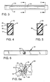
- Figures 4 and 5 are respectively cross-sectional illustrations taken through Figures 4-4 and 5-5 of Figure 3 showing portions of the sensor means.
- Figure 6 is a rear elevational view of the sensor of Figure 3.
- Figure 6a is a detail showing the electrical connector portion of the sensor.
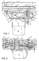
- Figure 7 is a top plan view of a form of apparatus of the present invention.
- Figure 8 is a rear elevational view of the apparatus shown in Figure 2.
- Figure 9 is a left-side elevational view of the apparatus shown in Figure 2.
- Figure 10 is a right-side elevational view of the apparatus shown in Figure 2.
- Figure 11 is a bottom plan view of the apparatus of Figure 2.
- Figure 12 shows a top plan view of a modified embodiment of the invention employing a sensor of reduced longitudinal extent.
- Figure 13 is a top plan view showing another embodiment of the invention wherein sensor means are provided on both sides of the path of travel of the container.
- Figure 14 is a schematic illustration showing the manner in which signals are delivered from various sensors to the electronic processor means.
- Figure 15 is a flow chart representative of a preferred practice of the method of the present invention.
- FIG. 1 there is shown a portion of an inspection system usable in the present invention.
- the system has inspection station 2 with a conveyor 4 moving a generally oval shaped container 10 to be inspected translationally in the direction of the arrow A.
- the container 10 is moved translationally and is also subjecting it to axial rotation by driven belt 14 which also serves to urge the container 10 into intimate contact with capacitive sensor means 12.
- the capacitive sensors means 12 take readings either (a) at predetermined intervals or (b) continuously as the container rotates thereagainst in order to monitor wall thickness about substantially the entire circumference of container 10. It will be appreciated that with oval containers, as they are subjected to axial rotation, the effective diameter of the portion in contact with the sensor means 12 will vary. It is necessary to compensate for variance in order to avoid distortion of the thickness reading due to such diameter variations.
- non-round annular containers will refer to containers having the portion which is being inspected not of round configuration and yet being annular in the sense of not having comers that would interfere with rolling action of the containers, such as would occur with containers which are rectangular, triangular or polygonal. It will expressly embrace oval-shaped containers and other non-round containers capable of rolling along the sensing means for sequential inspection thereof.
- the container 20 is shown as a glass or plastic bottle, although it will be appreciated that the invention may be employed with other dielectric containers, such as jars, for example.
- the container 20 is moving in the direction indicated by arrow B and is being urged into intimate contact with the sensor means, which in the form shown, consists of four elongated sensors 22, 24, 26, 28 which are generally parallel to each other, extend along the direction of movement of container 20, and are relatively vertically spaced from each other. They also have their surfaces closest to the container 20 in generally aligned position with respect to each other.
- the sensor means which in the form shown, consists of four elongated sensors 22, 24, 26, 28 which are generally parallel to each other, extend along the direction of movement of container 20, and are relatively vertically spaced from each other. They also have their surfaces closest to the container 20 in generally aligned position with respect to each other.
- the container 20 moves rotationally and translationally in the direction of arrow B and is urged into intimate contact with the sensors 22, 24, 26, 28, readings will be taken at each of the four levels containing the sensors 22, 24, 26, 28.
- the container is being transported on conveyor 30. It will be appreciated that as the container progressively rotates on the sensors 22, 24, 26, 28, the capacit
- the sensor 30 has a sensor strip 32 which, in the form shown, may be composed of a dielectric material, such as a polyolefin, such as polypropylene, for example.
- a dielectric material such as a polyolefin, such as polypropylene, for example.
- the sensing area which will be in contact with the container being inspected.
- the region of the sensor strip 32 has an electrically conductive surface, such as by applying an electrically conductive paint of a thickness of about 0.002 to 0.005 inch as by silk screening or spraying.
- the sensor 30, which may be a block of a suitable dielectric material, has sensor area 32 covered with an electrically conductive material and is surrounded by an uncoated region which is a dielectric frame surrounding sensor element 32. Upper and lower portions 33, 34 of this dielectric frame are shown in Figure 4. The remainder of the surface of sensor 30 is also coated with an electrically conductive material which is indicated generally by reference number 35. In this manner, sensor 32 serves as one plate of the capacitor and coated region 35 serves as the other plate of the capacitor.
- the sensor 30 has an overlying tape member 36 which is adapted to resist sensor wear on the front face which contacts the container.
- the tape member 36 may be made of a suitable dielectric material which is sufficiently thin as to not interfere with the functioning of the sensor area.
- FIG 5 there is shown a cross-section of the sensor in a region which is entirely coated with the conductive layer 34. The sensor area 32 is not present in this area.
- Figures 6 and 6a shows the reverse side of sensor 32 and shows the recess 40 in the reverse side of sensor 30 which contains the electrical contacts for transmitting the output of sensor 30 to the other processing means in the system.
- the inductor 36 which is part of the tuned circuit, is positioned within recess 40 and electrically connected by a suitable cable to the oscillator electronics which are not mounted on the sensor 30.
- the inductor 36 has coils 37 and is connected as an autotransformer. One lead of the primary coil and one lead of the secondary coil are secured to the oscillator cable connector 42 by leads 38, 39. respectively. Lead 39 is connected to the inner insulated contact 44 of connector 42. Lead 45 of inductor 36 is connected to sensor strip 32.
- the oscillator cable connector 42 through fasteners 46, 48 are electrically connected to the larger painted area 35. In this manner, changes in capacitance caused by container inspection will be transmitted through oscillator cable connector 42 to the oscillator electronics for conversion to corresponding voltage signals.
- FIG. 7 there is shown an oval container 46 being urged into contact with capacitive sensor means 48 by belt 50.
- the container is traveling in the direction indicated by arrow C.
- the sensor means 48 consists of four sensor elements with only the uppermost sensor 53 shown in this view.
- This sensor 53 has a sensor strip 52 which is on the front face of sensor 53 and is in contact with the container 46 and a back-up bar 54 which is secured to the sensor 53 through resilient foam. It is desirable to have the sensor assembly 52, 53, 54 be relatively lightweight and flexible.
- a pivotable linkage member 60 Secured to back-up bar 54 is a pivotable linkage member 60 which is secured through suitable pivot pin 62 to connector member 64 which connects the same to back-up bar 54.
- Fastener 66 of the linkage member 60 which, in the form shown, is generally triangular, serves as a pivot for the linkage member 60.
- Fastener 68 is rotatable responsive to rotational movement of the linkage bar 60. In the form illustrated, if the container 46 were to have an enlarged diameter portion come in contact with the sensor means 48, at point P illustrated on the sensor 53, it would tend to deform the sensor means 48 in a direction generally downwardly with respect to Figure 7. This, in turn, would cause counter-clockwise rotation of the linkage means 60 in the direction indicated by arrow D.
- Linkage member 76 is, in the form shown, generally triangular in shape and has a pivot pin 78 securing the same to bracket 72, a pivotal fastener 80, which is secured to a support member, and a fastener 82 which secures the linkage to linkage bar 85 which connects linkage element 60 and 76.
- a displacement monitor 84 which, in the form indicated is a transducer, has a movable element 86 secured to linkage member 76 through pivot pin 78.
- the displacement means 84 will be a transducer which will emit an electrical signal which corresponds to the degree of mechanical movement over lead 90 by lead 91 to oscillator means 93 which is an oscillator circuit board within a housing.
- An oscillator cable 95 connects sensor 53 through connector 42 (Fig. 6a) to oscillator means 93.
- Each sensor will have a similar connector to oscillator means 93.
- the oscillator means contain all of the oscillator components except for the tuned circuit inductor and capacitor (Fig. 6a).
- a separate oscillator means 93, 97, 98, 99 (Fig. 8) is provided for each sensor 53, 100, 102, 104.
- Cable means connect each oscillator means 93, 97, 98, 99 to the electronic processor means through cables connected to contacts 101, 103, 105 (one not shown) with an interposed analog-to-digital converter and multiplexer contained in a separate enclosure (not shown in Fig. 8).
- the transducer may be electrically connected to any one of the oscillators 93, 97, 98. In a manner to be described in detail hereinafter, this electrical signal will be employed in compensating a thickness reading so as to adjust for diameter changes.
- FIGs 8 through 11 show additional details of the illustrated system which contains four sensors 53, 100, 102, 104.
- Each sensor 53, 100, 102, 104 has a back-up bar, such as 54, for example.
- the back-up bars are fixedly secured to posts 111, 113 (Figs. 7-11).
- the sensors 52, 100, 102, 104 function through a capacitance change providing a signal which alters the frequency of an oscillator circuit.
- the circuit has two frequency determining components, i.e., capacitance as presented by the sensor means and inductance which is provided by an inductor of fixed value.
- the sensor means function as plates of the capacitor with the glass of the container acting as the dielectric.
- the capacitor and inductor form a tank circuit whose natural resonant frequency is determined by the value of these components.
- This shift in frequency is related to the amount of change in glass thickness.
- the mass of the sensor means be kept as low as possible in order to permit the sensor assembly to be displaced in a rapid manner responsive to changes in contour of the non-circular container.
- a suitable sensor means thickness which preferably may be 0.250 to 0.350 inch.
- An appropriate sensor means material which may, for example, be polypropylene or polycarbonate and a suitable resilient back-up material which may be urethane foam.
- only the minimum necessary oscillator components be placed on the sensor means.
- a flexible cable connects the sensor to the rest of the oscillator. In this design, therefore, only the capacitor and inductor are contained in the sensor and the connecting cable need not be part of the tuned circuit. This eliminates the need for critically calibrated cables and makes the circuit substantially immune to problems with movement or tolerances of the cable. This results in improved accuracy and reliability of the measurements.
- the linear position sensor or displacement monitoring means 84 (FIG. 7) monitors change of position in one of the sensors. This change is directly proportional to changes in diameter of the container being inspected.
- oval container 46 is positioned with its major axis parallel to the direction of container translation (arrow C) with belt 50 and sensor 52 in intimate contact with opposite sides of the container 46.
- Means such as spring means may be provided to permit resilient displacement of the belt 50 or sensor 52 while preserving the desired intimacy of contact between the container 46 and the adjacent belt 50 and sensor 52.
- a preferred way of accomplishing this is to provide a spring or springs on the sensor assembly so as to permit movement of the sensor 52 transversely to the direction of travel (arrow C) of the container 46.
- an extension spring such as spring 87 ( Figure 8) will be in contact with pivot pin 82 such that in its unflexed position, the sensor 52 will be in the position shown in Figure 7 with the minor axis of the container transverse to the path of container travel.
- the spring 87 will normally keep the sensors in its closest relationship with respect to the belt 50 and will be urged transversely outwardly as the container rotates axially to position larger diameter portions in contact with the sensors.
- an oval container such as an elliptical container, cannot be the subject of simple measurement across either the minor or major axis in order to determine diameter.
- the electronic processor means which may be a suitable microprocessor programmed in a manner which will be well known to those skilled in the art, employs an equivalent diameter for calculating correction factors to be applied to the measured wall thickness of the container. The formulas are based upon the approximate cross-section of the container.
- the operator merely needs to enter the diameter of the calibration standard.
- the electronic processor checks the output signal from the position sensor means 84 and calculates displacements for the particular container position. This permits determination of the thickness correction factor which is required.
- the electronic microprocessor preferably contains a "look-up" table which contains thickness corrections corresponding to various displacements of the displacement means 84 so that there need not be a new calculation each time.
- the electronic processor means then applies the correction factor corresponding to a particular measure displacement to correct the thickness measurement and provide an accurate measure of thickness which is independent of the diameter of the particular portion of the non-round annular container being measured.
- the left and right elevational views shown respectively in Figures 9 and 10, show a jar 110 supported on conveyor 109 and made of a dielectric material in contact with the sensors 52, 100, 102, 104.
- Bracket 114 supports the transducer 84 (not shown in this view). As shown in Figures 9 and 10, each sensor 52, 100, for example, is operatively associated with oscillator means 120, 124 which have respectively electrical leads 122, 126 which serve to carry the oscillator output voltage which corresponds to container thickness to provide the same to the electronic processor means after passing through an analog-to-digital converter and multiplexer.
- the length of sensor L of the prior embodiment may be considered to extend between the two dashed lines 160, 162 shown in Figure 12.
- the length L' of sensor 170 of the embodiment of Figure 12 is substantially less than that of L.
- the length of the sensor strip portion of sensor 170 will correspond to the circumference of the portion of the container that it will contact.
- An additional length which may be about 11 ⁇ 2 inches on the upstream end and 1 ⁇ 2 inch on the downstream end may be provided to take care of the portion of the sensor which extends beyond the sensor strip.
- more than one container 172, 174, 176 is on conveyor 178 simultaneously even though only one will be in contact with sensor means 170 at a given time.
- the length L' of sensor 170 is sufficiently long to permit the sensor to inspect the entire circumference of a non-round container 172, 174, 176 which is moving translationally along container 178 and is also being subjected to axial rotation and being urged into intimate contact with the sensor means 170 by means not shown.
- Star wheel 180 serves to, in time coordinated fashion, release containers for movement on the conveyor in the direction indicated by G.
- Downstream of the sensor means is container 176 which is in contact with resiliently biased member 181 in order to facilitate efficient movement of the rotating non-round container.
- Slowdown motor 184 drives two slowdown belts on slowdown arm 182. This serves to reduce the speed of the containers and position the container in the center of conveyor 178 and urge the containers in the direction indicated by arrow H.
- element 181 which facilitates efficient discharge of containers, such as 176 and element 186, which can be resiliently mounted, each operate independently of the sensor means 170 and can thereby facilitate the presence of more than one container in the inspection area at one time, even though only one container would be in contact with the sensor means 170 at a given time.
- Another advantage of this embodiment, as well as the embodiment of Figure 13, is that the use of reduced length sensors serve to reduce the mass of the sensors which, in turn, makes them more sensitive to sensor displacement by the containers.
- FIG 13 shows another embodiment of the invention wherein duplicate inspection assemblies 210, 212 each have, respectively, capacitive sensor means 214, 216 which may consist of a plurality of vertically spaced sensors for inspecting non-round annular container 220.
- each inspection unit 210, 212 may inspect a certain number of circumferential points with the two of them in the aggregate inspecting the number of circumferential points on the container desired to be inspected.
- the sensor means 214, 216 can be relatively short as each, in principle, need inspect only in the aggregate approximately 180° of the circumference rather than having a single sensor as in the other embodiments inspect substantially the entire circumference.
- Figure 14 illustrates, in general, the sequence of operations in inspecting non-round containers by the present invention.
- a series of four capacitive sensors 240, 242, 244, 246, all disposed on one side of the path of travel of containers being inspected, have output signals corresponding to the thickness of the portion of the container which has been measured introduced, respectively, into oscillators 250, 252, 254, 256 which produces corresponding voltage signals containing thickness information. All of these voltage signals from the oscillators 250, 252, 254, 256 are introduced into multiplexer 260 from which they are selectively introduced through analog-to-digital converter 262 into the electronic processor means which, in the form shown, is a computer 264.
- the computer 264 calculates thickness at the four elevations monitored at each circumferential point being monitored by the sensors 240, 242, 244, 246 as the container is subjected to rotational and translational movement.
- the position transducer 84 emits an electrical displacement voltage signal which enters multiplexer 260 and is converted to a digital pulse in analog-to-digital converter 262 and is introduced into the computer 264.
- the computer contains a look-up table, which for a given diameter calibration previously set by the operator produces a diameter correction factor corresponding to the displacement of each of the sensors 240, 242, 244, 246.
- the computer 264 combines the calculated container thickness at a particular point with the adjustment factor and produces a reliable and accurate thickness reading at the position monitored.
- This signal may be stored in computer 264 or may be delivered to interfacing means 270 so as to provide a hard copy printout, a monitor display or to activate a reject mechanism (not shown), or visual or audible alarm, if desired.
- a look-up table has been selected based upon the calibration process which is dependent upon the approximate diameter sizes of the container such as the major and minor axes of an oval container.
- a suitable calibration adjustment for a glass or plastic which have different dielectric constants may be made as by adjusting the gain of the circuitry.
- the displacement value is received in the electronic processor and is compared with a value in the look-up table to get an appropriate correction value based upon the change in diameter as reflected through the displacement reading.
- the inspection ready block 270 indicates that the data is available. It is delivered to the read displacement block 272 and the displacement correction 274 is found through comparison with the look-up table. The calculated corrected thickness number 276 is then obtained and the output is linearized 278. The thickness result 280 is then saved. If there is no additional data 290, through line 292, the existing results are reported at 294. If there is additional data, it is delivered over lead 296 to the read displacement block 272 with additional processing occurring at that point. This cycle is continued until the inspection of a given container is completed after which the results may be stored, displayed or employed to automatically reject a container which does not have a thickness within the desired range.
- the system may be employed with or without thickness measurement to detect variations in diameter of a container which is designed to be round in the region inspected or to provide on-line measurement of container diameter regardless of container shape.
- the equipment and methods disclosed herein could be employed for such a purpose by employing the diameter voltage signal received from transducer 84 to the electronic processing means 264 for conversion into an absolute diameter or for comparison with a desired diameter and determining the amount of departure therefrom.
- the diameter information could be stored, enhanced, printed in hard copy, employed to activate a reject mechanism, or employed to provide an on-line monitor display. If desired, the diameter measuring portions of the system could be provided as a separate system directed toward diameter determinations.
- the sensor means could be substituted for by container contacting means which could be of the same structural configuration as the sensor means, but would not require the capacitive components.
- container contacting means which could be of the same structural configuration as the sensor means, but would not require the capacitive components.
- one or more elongated container contacting members which would displace the transducer 84 through intermediate linkage means, which could be of the type disclosed, could be employed.
- resilient mounting of the container contacting means should be employed.
- sensors will be provided on both sides of the path of container travel. This is true regardless of whether one is employing the thickness measurement embodiment or the embodiment which is employed to measure diameter independent of a thickness determination.
- resilient means such as spring 87, are employed to establish relative movement between the sensor means on one side of the path of container travel and either (a) the means for urging the containers into contact with the sensor means, or (b) a second set of sensor means disposed on the opposite side of the path. This relative movement can be established by either movement of sensor means on one side or movement of the container urging means or second sensor of sensor means.
- both the sensor means on one side of the path and either the (a) container urging means, or (b) second set of sensor means on the other side of the path may be employed to effect such relative movement.
- This relative movement provides for adjustment of relative spacing to accommodate differences in the containers transverse dimension as a non-round container rotates axially while preserving the desired intimacy of contact with the container.
- the apparatus and method of the present invention facilitates efficient, rapid reliable inspection at high speed of a large number of non-round containers composed of dielectric material. This is accomplished without having to rely on a sampling technique.
- the system automatically compensates for changes in diameter of the various portions that sequentially contact the capacitive sensor means.
- the invention may also be employed to inspect containers for variations in diameter within a container and to provide on-line diameter measurement.
- the invention is not so limited and may be employed on glass or plastic jars and other containers composed entirely or partially of dielectric material.
- the choice of material would involve an initial calibration keyed to the material as the glass and plastic, for example, have different dielectric properties, however, the system will function essentially the same once the calibration has been accomplished.
Landscapes
- Physics & Mathematics (AREA)
- General Physics & Mathematics (AREA)
- Measurement Of Length, Angles, Or The Like Using Electric Or Magnetic Means (AREA)
Applications Claiming Priority (2)
| Application Number | Priority Date | Filing Date | Title |
|---|---|---|---|
| US330323 | 1994-10-27 | ||
| US08/330,323 US5532605A (en) | 1994-10-27 | 1994-10-27 | Container inspection apparatus having diameter measuring means and associated method |
Publications (3)
| Publication Number | Publication Date |
|---|---|
| EP0709649A2 true EP0709649A2 (de) | 1996-05-01 |
| EP0709649A3 EP0709649A3 (de) | 1996-11-27 |
| EP0709649B1 EP0709649B1 (de) | 2002-11-06 |
Family
ID=23289254
Family Applications (1)
| Application Number | Title | Priority Date | Filing Date |
|---|---|---|---|
| EP95113482A Expired - Lifetime EP0709649B1 (de) | 1994-10-27 | 1995-08-28 | Behälterinspektion mit Durchmessermesseinrichtung |
Country Status (4)
| Country | Link |
|---|---|
| US (3) | US5532605A (de) |
| EP (1) | EP0709649B1 (de) |
| DE (1) | DE69528740T2 (de) |
| ES (1) | ES2186698T3 (de) |
Cited By (2)
| Publication number | Priority date | Publication date | Assignee | Title |
|---|---|---|---|---|
| US7426223B2 (en) | 2004-04-09 | 2008-09-16 | Matsushita Electric Industrial, Co., Ltd. | Coherent light source and optical device |
| CN116140242A (zh) * | 2023-02-27 | 2023-05-23 | 重庆华彬伟玻璃有限公司 | 一种用于扁平玻璃瓶生产线的凹身检测系统 |
Families Citing this family (15)
| Publication number | Priority date | Publication date | Assignee | Title |
|---|---|---|---|---|
| US5558233A (en) * | 1994-10-27 | 1996-09-24 | Agr International, Inc. | Container inspection apparatus for determining the wall thickness of non-round containers and associated method |
| US5675516A (en) * | 1995-09-27 | 1997-10-07 | Inex Vision Systems, Inc. | System and method for determining pushup of a molded glass container |
| US6536294B1 (en) * | 1997-05-14 | 2003-03-25 | Emhart Glass S.A. | Inspection machine |
| US5923419A (en) * | 1997-06-16 | 1999-07-13 | Insight Control Systems International | System and method for optical inspection of recessed surfaces |
| US6061125A (en) * | 1998-01-27 | 2000-05-09 | Insight Control Systems International | Dual illumination apparatus for container inspection |
| FR2796143B1 (fr) | 1999-07-07 | 2001-09-21 | Xeda International | Dispositif d'evaluation de la geometrie d'articles transportes par un convoyeur |
| US6415526B1 (en) * | 2000-04-28 | 2002-07-09 | Smithkline Beecham Corporation | Apparatus and method for measuring alignment of metered dose inhaler valves |
| DE60011445D1 (de) * | 2000-11-28 | 2004-07-15 | St Microelectronics Srl | Textilartiger kapazitiver Drucksensor und Verfahren zum Abbilden des auf Punkte einer Oberfläche eines flexiblen und biegsamen Objekts, insbesondere eines Segels, ausgeübten Drucks |
| US20040111235A1 (en) * | 2002-12-09 | 2004-06-10 | Haskins Donald H. | Ultrasonic gauge online calibration system |
| US20090261221A1 (en) * | 2008-04-22 | 2009-10-22 | Damon Kali | Automated and illuminated cupholding devices and methods of use |
| EP4009032A1 (de) | 2014-04-21 | 2022-06-08 | Aber Instruments, Inc. | Partikelsensor mit störstoffdiskriminierung |
| JP6636464B2 (ja) * | 2015-01-21 | 2020-01-29 | 日本山村硝子株式会社 | 容器の肉厚検査装置 |
| DE102016211842B4 (de) * | 2016-06-30 | 2024-04-25 | Robert Bosch Gmbh | Bodenbearbeitungsgerät |
| CN110514097B (zh) * | 2019-09-12 | 2020-12-15 | 南通贝斯特钢丝有限公司 | 一种锚链直径检测设备 |
| DE102023125199A1 (de) * | 2023-09-18 | 2025-03-20 | Krones Aktiengesellschaft | Verfahren und Vorrichtung zum Bestimmen von Eigenschaften von aus Papier oder Pappe hergestellten Behältnissen |
Citations (8)
| Publication number | Priority date | Publication date | Assignee | Title |
|---|---|---|---|---|
| US2573824A (en) | 1946-10-17 | 1951-11-06 | Emhart Mfg Co | Machine for high-frequency determinations of wall thickness of bottles and the like |
| US4820972A (en) | 1987-07-02 | 1989-04-11 | Emhart Industries, Inc. | Wall thickness detector |
| US4862062A (en) | 1988-10-05 | 1989-08-29 | Emhart Industries, Inc. | Glass container inspection machine |
| US4870342A (en) | 1988-10-05 | 1989-09-26 | Emhart Industries, Inc. | Glass container wall thickness inspecting machine |
| US4930367A (en) | 1987-04-02 | 1990-06-05 | Koito Seisakusho Co., Ltd. | Perpendicularly intersecting gear device |
| US4965523A (en) | 1988-10-05 | 1990-10-23 | Emhart Industries, Inc. | Glass container inspection machine with rejection parameter selector |
| US4972566A (en) | 1988-10-05 | 1990-11-27 | Emhart Industries, Inc. | Method of repairing a glass container inspecting machine |
| US5097216A (en) | 1990-10-09 | 1992-03-17 | Agr International, Inc. | Apparatus for inspecting the wall thickness of a container and corresponding method |
Family Cites Families (21)
| Publication number | Priority date | Publication date | Assignee | Title |
|---|---|---|---|---|
| US2368796A (en) * | 1942-04-22 | 1945-02-06 | Standard Knapp Corp | Bottle removing apparatus |
| US2616068A (en) * | 1948-06-02 | 1952-10-28 | Emhart Mfg Co | Apparatus for gauging thickness |
| US2988218A (en) * | 1955-04-05 | 1961-06-13 | Owens Illinois Glass Co | Apparatus for gauging and inspecting glassware |
| US3080659A (en) * | 1961-03-06 | 1963-03-12 | Owens Illinois Glass Co | Container gauging apparatus |
| US3410402A (en) * | 1966-05-26 | 1968-11-12 | Armstrong Cork Co | Glassware inspection device |
| US3684089A (en) * | 1970-09-21 | 1972-08-15 | Brockway Glass Co Inc | Container wall thickness detection |
| US3779378A (en) * | 1973-01-31 | 1973-12-18 | Owens Illinois Inc | Apparatus and method for linearizing the output of a normally nonlinear radio frequency thickness gauge |
| US4077254A (en) * | 1977-04-25 | 1978-03-07 | Owens-Illinois, Inc. | Impact simulation apparatus |
| US4124112A (en) * | 1977-05-23 | 1978-11-07 | Owens-Illinois, Inc. | Odd-shaped container indexing starwheel |
| US4259571A (en) * | 1979-05-25 | 1981-03-31 | The Mead Corporation | Apparatus and method for container recognition |
| US4318808A (en) * | 1979-06-04 | 1982-03-09 | Ball Corporation | Inspection device for containers |
| JPS5659633A (en) * | 1979-10-23 | 1981-05-23 | Ishizuka Glass Ltd | Form inspecting apparatus for square bottle |
| US4414566A (en) * | 1981-04-03 | 1983-11-08 | Industrial Automation Corporation | Sorting and inspection apparatus and method |
| AT385121B (de) * | 1982-10-15 | 1988-02-25 | Steyr Daimler Puch Ag | Vorrichtung zum messen bzw. ueberwachen der durchmesser stabfoermiger werkstuecke |
| US4557386A (en) * | 1983-06-27 | 1985-12-10 | Cochlea Corporation | System to measure geometric and electromagnetic characteristics of objects |
| US4955227A (en) * | 1987-05-27 | 1990-09-11 | Toyo Garasu Kabushiki Kaisha | Apparatus for inspecting glass bottles |
| US4930364A (en) * | 1988-10-05 | 1990-06-05 | Emhart Industries, Inc. | Glass container inspecting machine |
| EP0363114B1 (de) * | 1988-10-05 | 1992-12-02 | Emhart Glass Machinery Investments Inc. | Glasbehälter-Prüfapparat |
| DE4031210A1 (de) * | 1990-10-04 | 1992-04-09 | Bosch Gmbh Robert | Kapazitiver sensor zur messung eines kraftstoffwandfilms |
| US5223796A (en) * | 1991-05-28 | 1993-06-29 | Axiomatics Corporation | Apparatus and methods for measuring the dielectric and geometric properties of materials |
| US5558233A (en) * | 1994-10-27 | 1996-09-24 | Agr International, Inc. | Container inspection apparatus for determining the wall thickness of non-round containers and associated method |
-
1994
- 1994-10-27 US US08/330,323 patent/US5532605A/en not_active Expired - Fee Related
-
1995
- 1995-08-28 EP EP95113482A patent/EP0709649B1/de not_active Expired - Lifetime
- 1995-08-28 DE DE69528740T patent/DE69528740T2/de not_active Expired - Fee Related
- 1995-08-28 ES ES95113482T patent/ES2186698T3/es not_active Expired - Lifetime
-
1996
- 1996-02-20 US US08/603,125 patent/US5604442A/en not_active Expired - Fee Related
- 1996-09-27 US US08/723,185 patent/US5723797A/en not_active Expired - Fee Related
Patent Citations (8)
| Publication number | Priority date | Publication date | Assignee | Title |
|---|---|---|---|---|
| US2573824A (en) | 1946-10-17 | 1951-11-06 | Emhart Mfg Co | Machine for high-frequency determinations of wall thickness of bottles and the like |
| US4930367A (en) | 1987-04-02 | 1990-06-05 | Koito Seisakusho Co., Ltd. | Perpendicularly intersecting gear device |
| US4820972A (en) | 1987-07-02 | 1989-04-11 | Emhart Industries, Inc. | Wall thickness detector |
| US4862062A (en) | 1988-10-05 | 1989-08-29 | Emhart Industries, Inc. | Glass container inspection machine |
| US4870342A (en) | 1988-10-05 | 1989-09-26 | Emhart Industries, Inc. | Glass container wall thickness inspecting machine |
| US4965523A (en) | 1988-10-05 | 1990-10-23 | Emhart Industries, Inc. | Glass container inspection machine with rejection parameter selector |
| US4972566A (en) | 1988-10-05 | 1990-11-27 | Emhart Industries, Inc. | Method of repairing a glass container inspecting machine |
| US5097216A (en) | 1990-10-09 | 1992-03-17 | Agr International, Inc. | Apparatus for inspecting the wall thickness of a container and corresponding method |
Cited By (2)
| Publication number | Priority date | Publication date | Assignee | Title |
|---|---|---|---|---|
| US7426223B2 (en) | 2004-04-09 | 2008-09-16 | Matsushita Electric Industrial, Co., Ltd. | Coherent light source and optical device |
| CN116140242A (zh) * | 2023-02-27 | 2023-05-23 | 重庆华彬伟玻璃有限公司 | 一种用于扁平玻璃瓶生产线的凹身检测系统 |
Also Published As
| Publication number | Publication date |
|---|---|
| US5532605A (en) | 1996-07-02 |
| DE69528740D1 (de) | 2002-12-12 |
| US5723797A (en) | 1998-03-03 |
| US5604442A (en) | 1997-02-18 |
| DE69528740T2 (de) | 2003-03-13 |
| ES2186698T3 (es) | 2003-05-16 |
| EP0709649B1 (de) | 2002-11-06 |
| EP0709649A3 (de) | 1996-11-27 |
Similar Documents
| Publication | Publication Date | Title |
|---|---|---|
| EP0709649B1 (de) | Behälterinspektion mit Durchmessermesseinrichtung | |
| KR900007288B1 (ko) | 연속체의 연속 측정 방법 | |
| US20050206373A1 (en) | Metallic contaminant detecting method and apparatus therefor | |
| EP0709650B1 (de) | Behälterprüfverfahren und -vorrichtung zum Feststellen der Wanddicke von nicht runden Behältern | |
| AU599297B2 (en) | Wall thickness detector | |
| US20020067163A1 (en) | Apparatus and method for detecting metallized containers in closed packages | |
| JPS5920806A (ja) | シ−ト状材料を測定する方法及び装置 | |
| US4528651A (en) | Method and apparatus for measurement of length and height of objects | |
| US7107852B2 (en) | Method of inspecting food stuffs and/or associated packaging | |
| US4750368A (en) | Bond strength measurement of composite panel products | |
| Kandala et al. | Capacitive sensors for measuring single-kernel moisture content in corn | |
| US4470307A (en) | Sonic system inspection control | |
| CN85106686B (zh) | 连续传送的长物体的连续测量方法 | |
| US5251487A (en) | Apparatus for acoustically coupling an ultrasonic transducer with a body | |
| US5641357A (en) | Apparatus for checking glue application state | |
| KR930002387B1 (ko) | 관의 곧음(straightness) 측정방법 및 그 장치 | |
| Kandala et al. | Instrument for single-kernel nondestructive moisture measurement | |
| EP0577880A1 (de) | Vorrichtung zur Feststellung von Fehlern bei Tragetaschen mit Handgriff | |
| JPH09166599A (ja) | 血液分注ラインの液面検知センサ | |
| JPS6315538B2 (de) | ||
| US5694809A (en) | Dough sheet sensor | |
| JP2995573B2 (ja) | 非破壊検査方法 | |
| JP2001082908A (ja) | 瓶の肉厚検査装置 | |
| US5056367A (en) | Ultrasonic linear measurement system | |
| JP2909284B2 (ja) | 非破壊検査装置の容器位置決め装置 |
Legal Events
| Date | Code | Title | Description |
|---|---|---|---|
| PUAI | Public reference made under article 153(3) epc to a published international application that has entered the european phase |
Free format text: ORIGINAL CODE: 0009012 |
|
| AK | Designated contracting states |
Kind code of ref document: A2 Designated state(s): CH DE ES FR GB IT LI |
|
| PUAL | Search report despatched |
Free format text: ORIGINAL CODE: 0009013 |
|
| AK | Designated contracting states |
Kind code of ref document: A3 Designated state(s): CH DE ES FR GB IT LI |
|
| 17P | Request for examination filed |
Effective date: 19970424 |
|
| 17Q | First examination report despatched |
Effective date: 19990629 |
|
| RTI1 | Title (correction) |
Free format text: CONTAINER INSPECTION WITH DIAMETER MEASUREMENT |
|
| GRAG | Despatch of communication of intention to grant |
Free format text: ORIGINAL CODE: EPIDOS AGRA |
|
| GRAG | Despatch of communication of intention to grant |
Free format text: ORIGINAL CODE: EPIDOS AGRA |
|
| GRAH | Despatch of communication of intention to grant a patent |
Free format text: ORIGINAL CODE: EPIDOS IGRA |
|
| GRAH | Despatch of communication of intention to grant a patent |
Free format text: ORIGINAL CODE: EPIDOS IGRA |
|
| GRAA | (expected) grant |
Free format text: ORIGINAL CODE: 0009210 |
|
| AK | Designated contracting states |
Kind code of ref document: B1 Designated state(s): CH DE ES FR GB IT LI |
|
| REG | Reference to a national code |
Ref country code: GB Ref legal event code: FG4D |
|
| REG | Reference to a national code |
Ref country code: CH Ref legal event code: EP |
|
| REF | Corresponds to: |
Ref document number: 69528740 Country of ref document: DE Date of ref document: 20021212 |
|
| REG | Reference to a national code |
Ref country code: CH Ref legal event code: NV Representative=s name: PATENTANWAELTE SCHAAD, BALASS, MENZL & PARTNER AG |
|
| REG | Reference to a national code |
Ref country code: ES Ref legal event code: FG2A Ref document number: 2186698 Country of ref document: ES Kind code of ref document: T3 |
|
| ET | Fr: translation filed | ||
| PG25 | Lapsed in a contracting state [announced via postgrant information from national office to epo] |
Ref country code: LI Free format text: LAPSE BECAUSE OF NON-PAYMENT OF DUE FEES Effective date: 20030831 Ref country code: CH Free format text: LAPSE BECAUSE OF NON-PAYMENT OF DUE FEES Effective date: 20030831 |
|
| PLBE | No opposition filed within time limit |
Free format text: ORIGINAL CODE: 0009261 |
|
| STAA | Information on the status of an ep patent application or granted ep patent |
Free format text: STATUS: NO OPPOSITION FILED WITHIN TIME LIMIT |
|
| 26N | No opposition filed |
Effective date: 20030807 |
|
| REG | Reference to a national code |
Ref country code: CH Ref legal event code: PL |
|
| PGFP | Annual fee paid to national office [announced via postgrant information from national office to epo] |
Ref country code: FR Payment date: 20050809 Year of fee payment: 11 |
|
| PGFP | Annual fee paid to national office [announced via postgrant information from national office to epo] |
Ref country code: GB Payment date: 20050824 Year of fee payment: 11 |
|
| PGFP | Annual fee paid to national office [announced via postgrant information from national office to epo] |
Ref country code: DE Payment date: 20050825 Year of fee payment: 11 |
|
| PGFP | Annual fee paid to national office [announced via postgrant information from national office to epo] |
Ref country code: ES Payment date: 20050927 Year of fee payment: 11 |
|
| PGFP | Annual fee paid to national office [announced via postgrant information from national office to epo] |
Ref country code: IT Payment date: 20060831 Year of fee payment: 12 |
|
| PG25 | Lapsed in a contracting state [announced via postgrant information from national office to epo] |
Ref country code: DE Free format text: LAPSE BECAUSE OF NON-PAYMENT OF DUE FEES Effective date: 20070301 |
|
| GBPC | Gb: european patent ceased through non-payment of renewal fee |
Effective date: 20060828 |
|
| REG | Reference to a national code |
Ref country code: FR Ref legal event code: ST Effective date: 20070430 |
|
| REG | Reference to a national code |
Ref country code: ES Ref legal event code: FD2A Effective date: 20060829 |
|
| PG25 | Lapsed in a contracting state [announced via postgrant information from national office to epo] |
Ref country code: GB Free format text: LAPSE BECAUSE OF NON-PAYMENT OF DUE FEES Effective date: 20060828 |
|
| PG25 | Lapsed in a contracting state [announced via postgrant information from national office to epo] |
Ref country code: ES Free format text: LAPSE BECAUSE OF NON-PAYMENT OF DUE FEES Effective date: 20060829 |
|
| PG25 | Lapsed in a contracting state [announced via postgrant information from national office to epo] |
Ref country code: FR Free format text: LAPSE BECAUSE OF NON-PAYMENT OF DUE FEES Effective date: 20060831 |
|
| PG25 | Lapsed in a contracting state [announced via postgrant information from national office to epo] |
Ref country code: IT Free format text: LAPSE BECAUSE OF NON-PAYMENT OF DUE FEES Effective date: 20070828 |