EP0709665A2 - Messvorrichtung für die Biegebeanspruchung des Abdomens eines anthropomorphen Dummys und ihre Verwendung in einem Apparat zur Voraussage abdominaler Verletzungen - Google Patents
Messvorrichtung für die Biegebeanspruchung des Abdomens eines anthropomorphen Dummys und ihre Verwendung in einem Apparat zur Voraussage abdominaler Verletzungen Download PDFInfo
- Publication number
- EP0709665A2 EP0709665A2 EP95116765A EP95116765A EP0709665A2 EP 0709665 A2 EP0709665 A2 EP 0709665A2 EP 95116765 A EP95116765 A EP 95116765A EP 95116765 A EP95116765 A EP 95116765A EP 0709665 A2 EP0709665 A2 EP 0709665A2
- Authority
- EP
- European Patent Office
- Prior art keywords
- abdomen
- band
- bending strain
- deformation
- measurement apparatus
- Prior art date
- Legal status (The legal status is an assumption and is not a legal conclusion. Google has not performed a legal analysis and makes no representation as to the accuracy of the status listed.)
- Withdrawn
Links
Images










Classifications
-
- G—PHYSICS
- G01—MEASURING; TESTING
- G01M—TESTING STATIC OR DYNAMIC BALANCE OF MACHINES OR STRUCTURES; TESTING OF STRUCTURES OR APPARATUS, NOT OTHERWISE PROVIDED FOR
- G01M17/00—Testing of vehicles
- G01M17/007—Wheeled or endless-tracked vehicles
- G01M17/0078—Shock-testing of vehicles
Definitions
- This invention relates to a dummy abdominal deformation measurement apparatus, attached to an anthropomorphic dummy for collision tests, capable of measuring a time history of an abdominal deformation of such an anthropomorphic dummy as well as of presuming abdominal injuries.
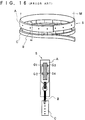
- a conventional dummy chest deformation measurement apparatus (SAE 892426) has a loop-shaped steel band S provided with gauges G1 to G4 which constitute a bridge circuit and with a cable B and a harness C.
- a dummy chest M enveloped by ribs is wound with the band S whose entire deformation is detected with the gauges G1 to G4.
- FIG. 17 Another conventional dummy abdomen deformation measurement apparatus (SAE 892440, 902317) as shown in Fig. 17 uses a material whose load-deformation characteristics are coincident with one of human being, whose elastic deformation is very small, and whose plastic deformation dominates deformation of the body, and detects the maximum deformation of the dummy's abdomen with a member U having plural spoke wise extending projections T whose outline is made to fit to the shape of the abdomen of a standard anthropomorphic dummy (Hybrid III).
- the conventional dummy chest deformation measurement apparatus which detects with the gauges G1 to G4 the entire deformation of the loop-shaped steel band S rounded over the dummy chest M enveloped by ribs, has a problem that such an apparatus is not suitable to detect local deformations at the abdomen at which no rib exists in the chest M but a spinal column exists, because local deformations of the abdomen at portions to which obstacles collide are required to be detected.
- the conventional dummy abdomen deformation measurement apparatus also has a problem that such an apparatus is unable to presume abdominal injuries, because the apparatus detects only the maximum deformation of the dummy's abdomen with the member U and does not measure a time history of the deformation of the dummy's abdomen.
- It is a still further object of the present invention to provide a bending strain measurement apparatus for an abdomen of an anthropomorphic dummy comprising a band constituted of an elastic thin plate member, arranged in a longitudinal direction of the abdomen, having one end thereof fixed in the vicinity of the abdomen of the dummy and a plurality of gauges arranged on the band in a longitudinal direction thereof for detecting a bending strain of the abdomen when an obstacle collides with the abdomen; and a measuring device for measuring time history of the bending strain based on bending strain of the respective portions of the band detected by the gauges arranged on the band as a time transition of the bending strain of the respective portions of the band.
- an abdominal injury presumption apparatus for an abdomen of an anthropomorphic dummy comprising a band constituted of an elastic thin plate member, arranged in a longitudinal direction of the abdomen, having one end thereof fixed in the vicinity of the abdomen of the dummy and a plurality of gauges arranged on the band in a longitudinal direction thereof for detecting a bending strain of the abdomen when an obstacle collides with the abdomen; a measuring device for measuring time history of the bending strain based on bending strain of the respective portions of the band detected by the gauges arranged on the band as a time transition of the bending strain of respective portions of the band; a deformation and deformational velocity measurement device for measuring time histories of deformation and deformational velocity of the respective portions of the band, based on bending strain of the respective portions of the band detected by the gauges; and an injury presumption device for presuming abdominal injuries based on the time histories of the deformation and deformational velocity.
- a bending strain measurement apparatus of the abdomen of an anthropomorphic dummy detects bending strain of the abdomen when an obstacle collides with the abdomen, with multiple gauges arranged on and along a band constituted of an elastic thin plate member whose one end is fixed and which is arranged along in a longitudinal direction on a front face of the abdomen, thereby measuring the time history of the bending strain, based on the bending strain of the respective portions of the band which is detected with the respective gauges, as time transitions of the bending strain of respective portions of the band with regard to time.
- the deformation and deformational velocity measuring device measures the time histories of the deformation and deformational velocity, based on the bending strain of the respective portions of the band detected with the respective gauges as time transitions of the deformation and deformational velocity of respective portions of the band, and the injury presumption device presumes abdominal injury based on the time histories of the measured deformation and deformational velocity.
- the elastic thin plate member constituting the band is inserted into a guide member formed along with the abdomen, and either a friction reduction member or the guide member itself reduces friction on the contacting surface between the guide member and the elastic thin plate member.
- the bending strain measurement apparatus for the abdomen of an anthropomorphic dummy detects bending strain of the abdomen when an obstacle collides with the abdomen with multiple gauges arranged on the band, and the measuring device measures the time history of the bending strain as the time transition of the bending strain of the respective portions of the band with regard to time, thereby effectuating to provide the bending strain's data serving as basic data for the detection of deformation of the dummy's abdomen as a partial deformation and to enable itself to presume abdominal injuries.
- the presumption apparatus of abdominal injury measures the time histories of deformation and deformational velocity of the respective portions of the band based on the bending strain of the respective portions of the band and has an advantage to enable itself to presume abdominal injuries.
- the bending strain measurement apparatus for the abdomen of an anthropomorphic dummy and the presumption apparatus of abdominal injury using the same has an advantage to enable itself to precisely measure such as deformation, the time histories of the deformation and the deformational velocity, presumptions of abdominal injuries based on them, and the like, since either the friction reduction member or the guide member itself, inserted at the contacting surface between the guide member and the elastic thin plate member, reduces friction exerted on the elastic thin plate member.
- a bending strain measurement apparatus for the abdomen of an anthropomorphic dummy of the first preferred embodiment comprises: a band 2, made of a rectangular elastic thin plate member 20 extending in a longitudinal direction on a front surface of an abdomen 10 of an anthropomorphic dummy 1, in which an end thereof is fixed at a lower end of the front surface of the abdomen 10 and in which multiple gauges 3 to detect the deformation of the abdomen 10 when a belt 15 as an obstacle collides with the abdomen are arranged in a longitudinal direction; and a deformation measuring device 4 for measuring a time history of a bending strain based on the detected bending strain of the respective portions of the band 2 by said gauges arranged on the band 2 as a time transition of the bending strain of the respective portions of the band 2.
- the dummy 1 is formed with a pelvis 12 arranged on legs 11 placed at the lowest position, the abdomen 10 placed in front of a spinal column 13 arranged on the pelvis 12 and made of foam rubber, such as Neoprene 15 (trademark), and a thorax 14 placed over the abdomen 10.
- foam rubber such as Neoprene 15 (trademark)
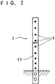
- the band 2 comprises the rectangular elastic thin plate member 20 which is made of a stainless steel strip (SUS 301)of 296 mm in length, 12.7 mm in width, and 0.1 mm in thickness, as shown in Figs. 1 and 2, and is secured at its lower end by two bolts to a fixing portion located at a lower front portion of the abdomen 10.
- SUS 301 stainless steel strip
- a plurality of, for example, fifteen pieces of the gauges 3, are arranged, as shown in Figs. 2 and 3, on the rectangular elastic thin plate member 20 in a longitudinal direction thereof. Subsequently, a flexible printed circuit forming the elastic thin plate member and a lead wire portion is placed on a Teflon sheet of 0.13 mm in thickness, one side of which is coated with adhesive, to mutually position them. After wiring for measurement is made between the respective gauges on the elastic thin plate member and the flexible printed board, another Teflon sheet of 0.13 mm in thickness is made to cover the top of those, thereby forming a band in a united body. Accordingly, the band is formed with Teflon sheets covering the top and bottom surfaces thereof.
- the deformation measuring device 4 is made to be able to measure and calculate a time history of the deformation through obtaining a time transition of the deformation of respective portions based on the deformation of the respective portions of the band 2 detected by the gauges 3 arranged on the band 2 when the belt 15 collides with the dummy 1.
- Equation 2 unknown quantities a i , i+1 , b i , i+1 , c i , i+1 are determined under the following conditions.
- Equation 5 since the first degree coefficient of the curvature is continuous at the strain gauge positions (S1 to s n ), the following Equation 5 is given.
- the unknown quantities a i , i+1 , b i , i+1 , c i , i+1 in Equation 2 are determined, thereby determining the curvature distribution k(s) as a distribution formula of the curvature in the longitudinal direction.
- the following description is the detailed process of determination of the quantities.
- Equation 7 The following Equation 7 is obtained from Equations 3 and 4.
- Equation 8 The following Equation 8 is obtained by substituting b i , i+1 , b i+1 , i+2 of Equation 7 into Equation 5.
- Equation 9 is obtained from Equation 7.
- Equation 10 is obtained from Equation 3.
- Fig. 5 shows an X-Y coordinate system and signs for obtaining the deformed curve of the abdominal surface.
- the zone Di between the strain gauge positions i and i+1 is further subdivided into small sections ds.
- the curvature distribution k(s) is assumed as a constant (or a part of the arc).
- Equation 11 is satisfied in the zones D1, D2, ..., D i-1 , so that Equation 12 can provide the respective inclinations ⁇ s where Equation 11 is applied to the zones D1 to D i-1 .
- the band 2 made of the rectangular elastic thin plate member 20 arranged in a longitudinal direction of the abdomen 10, having one end fixed to the lower end of the abdomen 10 of the dummy 1, is deformed according to deformation of the abdomen, so that by the multiple gauges 3 arranged in a longitudinal direction of the band 2, the deformation of the abdomen 10 is detected, so that based on deformation of respective portions of the band 2 detected by the gauges 3 arranged on the band 2, the deformation measuring device 4 calculates the curvature distribution of the respective portions and deformed shapes of the band 2 in the manner described above, and so that the deformation measuring device 4 measures the time history of the deformation as the time transition of the deformation.
- the shape of the band 2 being inputted can be deformed as the quadratic curve as shown in Fig. 6.
- the multiple gauges 3 arranged on the band 2 detect the deformation of the abdomen 10 when the belt 15 collides with the abdomen 10; the curvature distribution of the respective portions of the band 2 and the deformed shape of the band 2 are calculated; and the deformation measure apparatus measures the deformation on the time history as a transition of the deformation of the respective portions of the band 2.
- the deformation of the abdomen 10 of the dummy 1 is detected simultaneously and the injury of the abdomen 10 can be presumed.
- the presumption apparatus of abdominal injury using a bending strain measurement apparatus for the abdomen of an anthropomorphic dummy of the first preferred embodiment has an effect to be able to measure with high accuracy where the number of the strain gauges attached on the band 2 as shown in Fig. 7 to measure the curvature is increased.
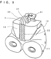
- a presumption apparatus of abdominal injury using a bending strain measurement apparatus for the abdomen of an anthropomorphic dummy of the second preferred embodiment, as shown in Figs. 8 to 12, is constituted of: a band 2, constituted of a rectangular elastic thin plate member 21 extended so as to be a U-shaped and held by a guide member 22 made of a low friction material and arranged in a longitudinal direction of the abdomen 10, on which multiple gauges 31 for detecting deformation of the abdomen 10 when an impacting member 16 or else serving as an obstacle collides with the abdomen 10 are arranged in a longitudinal direction; a deformation measuring device 4 for measuring a time history of the deformation, based on the deformation of the respective portions of the band 2 detected by the gauges 31 as a time transition of the deformation of the respective portions of the band 2; a deformational velocity measuring device 5 for measuring a time history of the deformational velocity, based on the deformation of the respective portions of the band 2 detected by the gauges 31 as a transition of the deformational velocity of the
- Figs. 8 and 9 show that the dummy 1 is formed with a pelvis 12 arranged on legs 11 placed at the lowest position, the abdomen 10 placed in front of a spinal column 13 constituting a waist being arranged on the pelvis 12 and made of foam rubber, as like Neoprene 15 (trademark) shown in Table 1, and a thorax 14 placed over the abdomen 10.
- the abdomen 10 was fabricated after six sheets of Neoprene 15 of 30 mm in thickness were stacked.
- a fabric for automobile seats is clamped between the second and third sheets from the front end of the abdomen to prevent the abdomen from rotating during receiving an impact; the lower end of the fabric is clamped by two sheets of aluminum alloy plate of 20 mm in length, 78 mm in width, and 3 mm in thickness with bolts and is fixed to the front end of a spine fixing block with two bolts.
- the band 2 comprises the rectangular elastic thin plate member 21 which is, as shown in Figs. 8 and 9, constituted of a strip-shaped stainless steel thin plate (SUS 301) of 380 mm in length, 12.7 mm in width, and 0.1 mm in thickness, which is selected from thickness tapes, fixed to a fixing portion in front of a lower spine with two bolts at a chamfered lower fixing end thereof, and disposed so as to extend U-shapely from the backside to the front abdomen side.
- SUS 301 strip-shaped stainless steel thin plate
- steel SUS 301 Cold Working Material
- this can be another metal thin plate having good spring characteristics except the steel or a non-metal material having good spring characteristics, such as a plastic thin plate.
- good spring characteristics means that a proportional limitation against the strain or elastic limitation in the material is great.
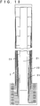
- the gauge 31 is constituted of a foil type single-axis gauge of 1 mm in length and 0.04 mm in thickness, and as shown in Figs. 10 and 11, the twenty five gauges 31 are attached onto the rectangular elastic thin plate member 21 in the longitudinal direction with variable strain gauge intervals of 12 to 18 mm, which intervals become narrow at a zone of larger deformation and become wide at a zone of smaller deformation.
- a flexible printed circuit provided in parallel to and corresponding to the strain gauges attached in the longitudinal direction of the rectangular elastic thin plate member 21 shown in Fig. 10, designed so that the resistances of the lead wires of the twenty five strain gauges become the same and so that the rigidity against bending becomes constant in the longitudinal direction, forms a lead portion 23.
- the strain gauges serving as sensors can be constituted of a foil piece of single semiconductor crystal attached onto a surface of a steel strip by insulating adhesive, or be formed by a thin film of semiconductor or conductor made by evaporating, sputtering, or etching after an insulating layer is formed on the steel strip surface.
- the strain gauge works, at least with changes of resistance; in this embodiment, it was constituted by making a foil gauge adhere.
- the gauge 31 constitutes, as shown in Fig. 12, a bridge circuit 23 through lead wires, and active gauges constitute one gauge method of one set of the Wheat stone Bridge.
- the rectangular elastic thin plate member 21 and the lead portion, as shown in Figs. 8 and 9, is enclosed in a Teflon sheet of 0.13 mm in thickness constituting a friction reducing member and is inserted in a guide member 22 constituted of a Teflon-made sheath of 0.08 mm in thickness attached to the front surface of the abdomen by a double-side adhesive tape.
- the deformation and deformational velocity measuring device 5 is constituted to calculate the curvature distribution and the deformed shape of the band 2 based on the bending strain of the respective portions of the band 2 detected by the gauges 31 arranged on the band 2 when the impacting member 16 collided, to obtain transitions of the deformations of the respective portions of the band, and thereby to be able to measure and calculate the deformation on the time basis.
- the deformation and deformational velocity measuring device 5 is constituted to obtain a time transition of the maximum deformation point within a zone at which the obstacle collided with the abdomen based on the bending strain of the portion of the band 2 detected by the gauges 3, to calculate the time differential of the amount of the deformation of the maximum deformation point, and thereby to be able to measure time histories of the deformation and the deformational velocity as the time transitions of the deformation and the deformational velocity of the respective portions of the band 2.
- the injury presumption device 6 is constituted to calculate the maximum value Cm of the time histories of the deformation C and the maximum value VCm of a product of the deformation C and the deformational velocity V, based on the time histories of the measured deformation C and deformational velocity V, to perform calculations to compare the calculated maximum values with an abdominal injury degree presumption reference, and thereby to be able to presume abdominal injuries.
- the band 2 comprising the rectangular elastic thin plate member 21 arranged from the center of the abdomen 10 in the longitudinal direction of the front surface of the abdomen 10, having one end fixed at the center lower end of the abdomen 10 of the dummy 1, is deformed according to the deformation of the abdomen 10.
- the deformation measuring device 4 calculates the curvature distribution of the respective portions of the band 2 and deformed shapes of the band 2 in the manner described above; the deformation measuring device 4 measures the deformation on the time basis as a time transition of the deformation; the deformational velocity device 5 measures the deformational velocity of the respective portions of the band 2 on the time basis; and the injury presumption device 6 presumes abdominal injuries based on the deformation and deformational velocity on the time basis.
- a pedestrian protection tester having a holder for fixing an impacting member, discharging the impacting member together with the holder in a horizontal direction or in a vertically downward direction with high speed, and having a function capable of colliding the member with a high speed to the dummy's abdomen set on a stable board, was used to conduct an impact shock test.
- the impacting member 16 was a cylindrical bar whose diameter was 50 mm, whose mass including the holder was 20 kg, and whose impacting speed was 3.01 meter per second; the deformation of the abdomen 10 of the dummy 1 was measured and analyzed by the dummy's abdominal deformation measurement apparatus of the second preferred embodiment and a high speed photography.
- the target position of the impacting member is located 31 mm below the top of the abdomen 10 and is equivalent to a position of 101 mm above the top of the lumbar-spine bracket.
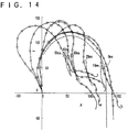
- the solid line is a measured result using the presumption apparatus of abdominal injury using a bending strain measurement apparatus for the abdomen of an anthropomorphic dummy and the dummy abdominal member according to the second preferred embodiment;
- the broken line is an analyzed result of the high speed photography; both show respective deformation modes at 0 (at the collision time), 10, 20, 30, and 40 milliseconds later from the collision of the impacting member 16 and have good similarity in the shapes at a time that the apparatus is attached to the abdomen and in the deformation modes of the abdomen 10 during the collision.
- the difference between them with respect to an impacting member's intrusion amount of about 96 mm at the time of 40 milliseconds was 7 percent.
- the maximum value VCm of a viscous criterion VC is calculated based on a body thickness (206 mm) of the apparatus of the second preferred embodiment, the measured value by the apparatus of the second preferred embodiment was 0.7 meter per second, whereas the value by the high speed photography was 0.8 meter per second.
- the deformation of the abdomen 10 when the impacting member 16 and the belt 15 collide with the abdomen 10 is detected by the multiple gauges 31 arranged on the band 2; the curvature distribution of the respective portions of the band 2 and the deformed shape of the band 2 are calculated; and the deformation measuring device 4 as shown in Figs. 13 to 15 measures the time history of the deformation as a time transition of the deformation of the respective portions of the band.
- the apparatus has an effect that the deformation of the abdomen 10 of the dummy 1 as a partial deformation is detected.
- the presumption apparatus of abdominal injury using a bending strain measurement apparatus for the abdomen of an anthropomorphic dummy of the second preferred embodiment has an effect that the abdominal injuries are identified since the deformational velocity measuring device 5 measures the time history of the deformational velocity of the respective portions of the band 2 and since the injury presumption device 6 presumes the abdominal injuries based on the time histories of the deformation and the deformational velocity.
- the presumption apparatus of abdominal injury using a bending strain measurement apparatus for the abdomen of an anthropomorphic dummy of the second preferred embodiment has an effect to reduce rigidity against bending and thereby to make it easier to be deformed because the rectangular elastic thin plate member 21 constituting the band 2 serving as sensors is constituted of a stainless steel thin strip as well as the lead portion is constituted of the flexible printed circuit and has an effect to make accurately measurable the deformed shape of the abdomen because axial strain never occurs during the deformation.
- the apparatus of the second preferred embodiment makes the rectangular elastic thin plate member 21 move easily even when locally large deformation occurs at the abdomen at the time of the collision and has an effect to prevent the rectangular elastic thin plate member 21 from sustaining tensional strain or being folded around the chamfered fixing portion, because the rectangular elastic thin plate member 21 constituting the band 2 is arranged so as to extend U-shapely from the rear side to the front side of the abdomen 10.
- the apparatus of the second preferred embodiment has an effect to reduce its rigidity against bending and attenuation force and to improve its response, because the rectangular elastic thin plate member 21 constituting the band 2 is constituted of a stainless steel thin strip as well as the lead portion is constituted of the flexible printed circuit.
- the apparatus of the second preferred embodiment makes the motion of the rectangular elastic thin plate member 21 smooth, thereby preventing the occurrence of the tensional strain in the rectangular elastic thin plate member 21, and having an effect to enable itself to accurately measure the deformed shape of the abdomen.
- the apparatus of the second preferred embodiment has an effect to be able to measure with high accuracy because twenty five of the strain gauges for measuring the curvature are attached onto the band 2.
- the apparatus of the second preferred embodiment has an effect to be able to accurately grasp the abdominal injuries because the abdomen 10 is constituted of a chloroprene rubber foam material Neoprene 15 (trademark) as a material matching the response characteristics of human body's abdomen at the impacting speed of 6 meter per second.
- Neoprene 15 trademark
- Table 1 shows chemical structures of four types materials of which load-bending characteristics are researched.
- spring hardness (degree) and apparent specific gravity(gf / cm3) are given respectively.
- the spring hardness and the apparent specific gravity are shown by values obtained according to Standard No. SRIS 0101 of the Society of Rubber Industry, Japan.
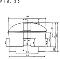
- Fig. 19 the load-bending characteristics, presented by Cavanaugh et al. at the SEA (SEA 861878, 1986), which was obtained by using a non-antiseptic dead body and an impacting member which is a cylindrical bar of 25 mm in diameter under the condition of the impacting speed of 6.1 meter per second and of the impacting mass of 31.4 kg, are shown together. According to Fig. 19, it turns out that Neoprene 15's characteristics is well coincided with the results of Cavanaugh's.
- EPT25'S characteristic is equivalent with the Neoprene 15's characteristic.
Landscapes
- Physics & Mathematics (AREA)
- General Physics & Mathematics (AREA)
- Length Measuring Devices With Unspecified Measuring Means (AREA)
- Measurement Of Length, Angles, Or The Like Using Electric Or Magnetic Means (AREA)
Applications Claiming Priority (2)
| Application Number | Priority Date | Filing Date | Title |
|---|---|---|---|
| JP6301315A JPH08122009A (ja) | 1994-10-27 | 1994-10-27 | ダミー腹部曲げひずみ計測装置、それを用いた腹部傷害推定装置 |
| JP301315/94 | 1994-10-27 |
Publications (2)
| Publication Number | Publication Date |
|---|---|
| EP0709665A2 true EP0709665A2 (de) | 1996-05-01 |
| EP0709665A3 EP0709665A3 (de) | 1997-02-05 |
Family
ID=17895378
Family Applications (1)
| Application Number | Title | Priority Date | Filing Date |
|---|---|---|---|
| EP95116765A Withdrawn EP0709665A3 (de) | 1994-10-27 | 1995-10-24 | Messvorrichtung für die Biegebeanspruchung des Abdomens eines anthropomorphen Dummys und ihre Verwendung in einem Apparat zur Voraussage abdominaler Verletzungen |
Country Status (3)
| Country | Link |
|---|---|
| US (1) | US5665922A (de) |
| EP (1) | EP0709665A3 (de) |
| JP (1) | JPH08122009A (de) |
Cited By (7)
| Publication number | Priority date | Publication date | Assignee | Title |
|---|---|---|---|---|
| DE19632273A1 (de) * | 1996-08-09 | 1998-02-12 | Helge Zwosta | Körpersensorik |
| LU90417A1 (fr) * | 1999-07-15 | 2001-01-16 | Iee Sarl | Outil de test |
| US9947244B2 (en) | 2015-04-02 | 2018-04-17 | Humanetics Innovative Solutions, Inc. | Adjustable spine joint assembly for crash test dummy |
| US9965977B2 (en) | 2014-12-31 | 2018-05-08 | Humanetics Innovative Solutions, Inc. | Adjustable lumbar spine assembly for crash test dummy |
| US9972220B2 (en) | 2014-12-31 | 2018-05-15 | Humanetics Innovative Solutions, Inc. | Omnidirectional neck assembly for crash test dummy |
| US10585019B2 (en) | 2015-12-28 | 2020-03-10 | Humanetics Innovative Solutions, Inc. | Neck assembly for anthropomorphic test device |
| US11823590B2 (en) | 2019-06-28 | 2023-11-21 | Humanetics Innovative Solutions, Inc. | Neck assembly for anthropomorphic test device |
Families Citing this family (14)
| Publication number | Priority date | Publication date | Assignee | Title |
|---|---|---|---|---|
| US6127672A (en) * | 1997-05-23 | 2000-10-03 | Canadian Space Agency | Topological and motion measuring tool |
| KR20010066071A (ko) * | 1999-12-31 | 2001-07-11 | 이계안 | 자동차의 충돌 시험용 인체 인형 |
| US6810753B2 (en) | 2000-08-29 | 2004-11-02 | The Cleveland Clinic Foundation | Displacement transducer |
| US7086273B2 (en) | 2003-12-05 | 2006-08-08 | First Technology Safety Systems, Inc. | Flexible printed circuit cabling system for crash test dummy |
| FR2901882B1 (fr) * | 2006-05-30 | 2008-08-29 | Cie Europ De Dev Ind C E D I S | Procede de conception de vetements ou equipements de protection pour le maintien de l'ordre,et procede d'homologation de tels vetements ou equipements |
| US8873785B2 (en) | 2007-12-11 | 2014-10-28 | Zounds Hearing, Inc. | Attenuating tip for hearing aid |
| US8596137B2 (en) | 2010-07-09 | 2013-12-03 | Alliant Techsystems Inc. | Methods, devices, and systems relating to a sensing device |
| JP5906990B2 (ja) * | 2012-08-09 | 2016-04-20 | 三菱自動車工業株式会社 | 人体模擬装置を用いた傷害値予測装置及び方法 |
| AT513245B1 (de) * | 2012-12-11 | 2014-03-15 | Siemens Vai Metals Tech Gmbh | Planheitsmessung und Messung der Eigenspannungen für ein metallisches Flachprodukt |
| JP6231932B2 (ja) * | 2014-03-31 | 2017-11-15 | 株式会社Subaru | 腰部シートベルトによる傷害状況の発信装置 |
| JP6231931B2 (ja) * | 2014-03-31 | 2017-11-15 | 株式会社Subaru | 衝撃度の算出装置 |
| CN104568463B (zh) * | 2014-12-30 | 2018-04-10 | 浙江吉利汽车研究院有限公司 | 汽车碰撞试验的假人腰椎测量工具 |
| WO2020061568A1 (en) * | 2018-09-21 | 2020-03-26 | Humanetics Innovative Solutions, Inc. | Coupling design for abdomen flesh of anthropomorphic test device |
| CN120927319B (zh) * | 2025-10-14 | 2026-01-20 | 中国汽车技术研究中心有限公司 | 汽车碰撞假人腹部安全测试装置及方法 |
Family Cites Families (10)
| Publication number | Priority date | Publication date | Assignee | Title |
|---|---|---|---|---|
| US3753302A (en) * | 1972-11-10 | 1973-08-21 | Ford Motor Co | Anthropomorphic test dummy torso |
| US4349339A (en) * | 1981-07-31 | 1982-09-14 | Ford Motor Company | Force-indicating dummy legs |
| DE3503577A1 (de) * | 1985-02-02 | 1986-08-14 | Daimler-Benz Ag, 7000 Stuttgart | Anatomisches modell, insbesondere dummy zur simulation einer unfallwirkung auf den menschlichen koerper |
| US4691556A (en) * | 1986-01-31 | 1987-09-08 | Ab Volvo | Load-sensing faceform for crash dummy instrumentation |
| US5018977A (en) * | 1989-04-21 | 1991-05-28 | Dynamic Research, Inc. | Motorcycle accident simulating test dummy |
| JPH05113311A (ja) * | 1991-10-22 | 1993-05-07 | Nippon Soken Inc | 三次元変位計 |
| FR2683320B1 (fr) * | 1991-10-31 | 1996-03-29 | Inrets | Capteur de pression intra-abdominale pour mannequin anthropomorphe. |
| FR2700206B1 (fr) * | 1993-01-04 | 1995-03-17 | Inrets | Dispositif pour analyser le phénomène de sous-marinage sur un mannequin anthropomorphe. |
| US5379646A (en) * | 1993-09-20 | 1995-01-10 | General Motors Corporation | Seatback load applying device |
| US5526707A (en) * | 1994-05-20 | 1996-06-18 | First Technology Safety Systems, Inc. | Fetal insert assembly for a female crash test dummy |
-
1994
- 1994-10-27 JP JP6301315A patent/JPH08122009A/ja active Pending
-
1995
- 1995-10-24 EP EP95116765A patent/EP0709665A3/de not_active Withdrawn
- 1995-10-26 US US08/548,476 patent/US5665922A/en not_active Expired - Fee Related
Non-Patent Citations (1)
| Title |
|---|
| None |
Cited By (8)
| Publication number | Priority date | Publication date | Assignee | Title |
|---|---|---|---|---|
| DE19632273A1 (de) * | 1996-08-09 | 1998-02-12 | Helge Zwosta | Körpersensorik |
| LU90417A1 (fr) * | 1999-07-15 | 2001-01-16 | Iee Sarl | Outil de test |
| US9965977B2 (en) | 2014-12-31 | 2018-05-08 | Humanetics Innovative Solutions, Inc. | Adjustable lumbar spine assembly for crash test dummy |
| US9972220B2 (en) | 2014-12-31 | 2018-05-15 | Humanetics Innovative Solutions, Inc. | Omnidirectional neck assembly for crash test dummy |
| US9947244B2 (en) | 2015-04-02 | 2018-04-17 | Humanetics Innovative Solutions, Inc. | Adjustable spine joint assembly for crash test dummy |
| US10585019B2 (en) | 2015-12-28 | 2020-03-10 | Humanetics Innovative Solutions, Inc. | Neck assembly for anthropomorphic test device |
| US10852216B2 (en) | 2015-12-28 | 2020-12-01 | Humanetics Innovative Solutions, Inc. | Neck assembly for anthropomorphic test device |
| US11823590B2 (en) | 2019-06-28 | 2023-11-21 | Humanetics Innovative Solutions, Inc. | Neck assembly for anthropomorphic test device |
Also Published As
| Publication number | Publication date |
|---|---|
| US5665922A (en) | 1997-09-09 |
| EP0709665A3 (de) | 1997-02-05 |
| JPH08122009A (ja) | 1996-05-17 |
Similar Documents
| Publication | Publication Date | Title |
|---|---|---|
| US5665922A (en) | Bending strain measurement apparatus for an abdomen of an anthropomorphic dummy and abdominal injury presumption apparatus using the same | |
| CA1095095A (en) | Load cell | |
| JP3792274B2 (ja) | 複数のせん断ひずみゲージを用いた六軸力センサ | |
| US4616511A (en) | Tactile sensor | |
| KR930020260A (ko) | 디스플레이 화면상에 인가된 힘의 접촉 위치를 결정하는 방법 및 그 감지 장치 | |
| Eppinger | On the development of a deformation measurement system and its application toward developing mechanically based injury indices | |
| JP3314107B2 (ja) | 加速度センサの取付構造 | |
| EP0429677B1 (de) | Messrobotersystem | |
| WO2005045388A1 (ja) | 歪みゲージ型センサおよびこれを利用した歪みゲージ型センサユニット | |
| EP0978714A2 (de) | Lastzelle | |
| US9003898B2 (en) | Multi-axis sensor | |
| EP0805961B1 (de) | Verfahren und vorrichtung zur messung von kräften in zwei richtungen und anwendung zur messung der zugkraft und des variablen ablenkungswinkels einer endlosen materialbahn | |
| Tsujimura et al. | A tactile sensing method for employing force/torque information through insensitive probes | |
| US7299138B2 (en) | Stress measurement method and its apparatus | |
| JP2004264235A (ja) | 構造物の損傷部位検出装置、及び構造物の損傷部位検出方法 | |
| US5042164A (en) | Means and method for calculating the instantaneous shape of the periphery of a cross-section of a body as it is being deformed | |
| JP2000213907A (ja) | 姿勢測定装置 | |
| US5373545A (en) | Method for the on-line nondestructive measurement of a characteristic of a continuously produced | |
| US7131340B2 (en) | Device for low-vibration force measurement in rapid dynamic tensile experiments on material samples | |
| JP2000162060A (ja) | ダミー胸部曲げひずみ計測装置、それを用いた胸部傷害推定装置 | |
| JPH0727781A (ja) | 流体の流速及び流れ方向検出器 | |
| JP3491294B2 (ja) | 曲げ加工方法及びその装置 | |
| JP3256709B2 (ja) | 車輪作用力測定装置 | |
| JPH1033506A (ja) | 着座姿勢計測装置および着座姿勢計測方法 | |
| EP0236955A2 (de) | Kabelinstallierungsverfahren |
Legal Events
| Date | Code | Title | Description |
|---|---|---|---|
| PUAI | Public reference made under article 153(3) epc to a published international application that has entered the european phase |
Free format text: ORIGINAL CODE: 0009012 |
|
| AK | Designated contracting states |
Kind code of ref document: A2 Designated state(s): NL |
|
| PUAL | Search report despatched |
Free format text: ORIGINAL CODE: 0009013 |
|
| AK | Designated contracting states |
Kind code of ref document: A3 Designated state(s): NL |
|
| 17P | Request for examination filed |
Effective date: 19970214 |
|
| 17Q | First examination report despatched |
Effective date: 19980130 |
|
| STAA | Information on the status of an ep patent application or granted ep patent |
Free format text: STATUS: THE APPLICATION IS DEEMED TO BE WITHDRAWN |
|
| 18D | Application deemed to be withdrawn |
Effective date: 19980610 |