EP0709684A2 - Procédé et dispositif pour déterminer et indiquer la direction du vent et la vitesse d'un véhicule aérien - Google Patents
Procédé et dispositif pour déterminer et indiquer la direction du vent et la vitesse d'un véhicule aérien Download PDFInfo
- Publication number
- EP0709684A2 EP0709684A2 EP95810658A EP95810658A EP0709684A2 EP 0709684 A2 EP0709684 A2 EP 0709684A2 EP 95810658 A EP95810658 A EP 95810658A EP 95810658 A EP95810658 A EP 95810658A EP 0709684 A2 EP0709684 A2 EP 0709684A2
- Authority
- EP
- European Patent Office
- Prior art keywords
- speed
- vector
- wind
- display
- amount
- Prior art date
- Legal status (The legal status is an assumption and is not a legal conclusion. Google has not performed a legal analysis and makes no representation as to the accuracy of the status listed.)
- Withdrawn
Links
Images


Classifications
-
- G—PHYSICS
- G01—MEASURING; TESTING
- G01P—MEASURING LINEAR OR ANGULAR SPEED, ACCELERATION, DECELERATION, OR SHOCK; INDICATING PRESENCE, ABSENCE, OR DIRECTION, OF MOVEMENT
- G01P5/00—Measuring speed of fluids, e.g. of air stream; Measuring speed of bodies relative to fluids, e.g. of ship, of aircraft
Definitions
- the invention relates to a method for determining and displaying the wind vector and the travel of an aircraft according to claim 8 and a device for performing the method according to claims 1 to 7.
- the object of the invention is therefore to provide a device which permanently displays the direction and strength of the wind and the amount of the average travel speed without the installation of a travel meter on the aircraft.
- the object of the present invention is to eliminate the disadvantages mentioned.
- the advantages achieved by the invention are that the pilot always takes into account the influence of the wind and can therefore take into account or use the prevailing winds, for example during competition and cross-country flights. For this information, which is always available, he will invest neither flight time nor attention, and will be able to react immediately to the creeping dangers of the weather.
- the block diagram shown in FIG. 1 of the device for determining and displaying the wind vector and the travel of an aircraft consists of a signal processing device 4, a control device 5, a display device 6, a control unit and various memories as well as inputs and outputs.
- a radio receiver with antenna 1 is used to generate signals which correspond to the geographic position and the vector of the basic speed.
- Such a marketable device is, for example, the GPS module for satellite navigation, the Earth's global positioning system (NAVSTAR Global Positioning System) from the Ministry of Defense the United States, which allows satellite data for civilian use.
- the signals of the position determining device 1, such as the measured values of the static air pressure 8, of the dynamic pressure 9 pass through the air data acquisition device 7 into the signal processing device 4, where it is processed according to instructions from the control device 5, displayed in the display device 6 and stored in the flight data acquisition devices 2 and 3.
- the display device 6 has, for example, four windows for the digital display of the speed over ground 20, the driving speed 21, the wind speed 22 and the barometric height 23.
- the prevailing wind 28 and anti-wind direction 27 appears in the form of bars on the stretched compass scale 24.
- the current speed vector over ground 25 is shown with another bar.
- the calculated azimuthal distribution of the amount of the speed vector 26, assuming an average constant driving speed, is shown as a development on the stretched compass scale 24.
- the device shown in Figure 1 is installed in a single housing, including the control panel, for example with various control buttons and with a power source, not shown, and attachments to the aircraft or, if the aircraft is a paraglider, for example on the harness at eye level of the pilot.
- the sequence of the essential steps for determining the average wind vector Vw from the basic speed vectors Vgi (t) with the amount Vgi and course K, which are stored as a function of the time t in the device 2 in FIG. 1, is formal in the flow chart in FIG mathematical Explanation of the steps (a ⁇ z) shown.
- the method delivers a good result within a few circles, since the basic speed Vg can be measured in many evenly distributed directions of flight at an approximately constant speed VL. Even without measuring the VL speed, the procedure is sufficiently precise if a paraglider pilot flies 90% of the flight time 30 ... 40 km / h and a delta pilot 40 ... 60 km / h. It is crucially important that the strong spread of the raw data measured every second, which is generated by the turbulence of the updrafts and, in the case of paragliders, by additional "oscillation", can largely be compensated for by averaging.
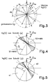
- FIG. 3 shows some basic speed vectors of a flight minute when circling, for example measured with satellite navigation.
- all vectors of a north-oriented polar coordinate system are displayed. If there was no wind, the basic speed, assuming constant driving, would be the same in all directions. Accordingly, the envelope of the ideally measured vectors would be a circle, the center of which coincides with the vector base.
- the basic speed vectors in FIG. 4 become smaller with a headwind component and those transverse to the wind and with a co-wind component are greater than the travel speed.
- the envelope curve in FIG. 5 is again a Circle whose center is shifted from the center of the polar coordinate system around the wind vector.
- step (b) the wind calculation is limited to a height range between Hu and Ho, analogous to the barometric height. If amounts of the velocity vectors as a function of the course are present in the azimuth sector dK ⁇ dKmax, in step (d) the average advertising is made to a VgMW (K) per course. If condition (c) is not met, the calculation (from "a") is repeated. In step (e), the assignment of the basic speed vectors is carried out for all courses (0 ...
- step (f) the summation of the data Vg (K) obtained in step (e) is repeated in two complementary 180 ° azimuth sectors S1, S2 until the average wind direction in step ( h) resp. (i) can be determined. This is the case when the partial sum S1 becomes maximum and S2 minimum.
- the subtotals S1, S2 of the two complementary 180 ° azimuth sectors are compared with the subtotals of the ideal functions s1, s2 related to the speed of travel 1 in steps (j, k,), equating the quotients. Because the related Comparison function which forms the sum of all vector amounts from 0 ... 360 ° (for example 1 vector per degree), for the comparison (k) it is necessary that all vector amounts 0 ... 360 ° are also available in the measured functions step (e) has been ensured.
- the calculation shown in FIG. 2 can be expanded to determine the average speed of travel (true air speed) because VLi (t) is also recorded for each Vgi (t) as a scalar measurement variable.
Landscapes
- Engineering & Computer Science (AREA)
- Aviation & Aerospace Engineering (AREA)
- Physics & Mathematics (AREA)
- General Physics & Mathematics (AREA)
- Traffic Control Systems (AREA)
Applications Claiming Priority (2)
| Application Number | Priority Date | Filing Date | Title |
|---|---|---|---|
| CH3197/94 | 1994-10-25 | ||
| CH319794 | 1994-10-25 |
Publications (2)
| Publication Number | Publication Date |
|---|---|
| EP0709684A2 true EP0709684A2 (fr) | 1996-05-01 |
| EP0709684A3 EP0709684A3 (fr) | 1997-01-02 |
Family
ID=4250763
Family Applications (1)
| Application Number | Title | Priority Date | Filing Date |
|---|---|---|---|
| EP95810658A Withdrawn EP0709684A3 (fr) | 1994-10-25 | 1995-10-25 | Procédé et dispositif pour déterminer et indiquer la direction du vent et la vitesse d'un véhicule aérien |
Country Status (1)
| Country | Link |
|---|---|
| EP (1) | EP0709684A3 (fr) |
Cited By (5)
| Publication number | Priority date | Publication date | Assignee | Title |
|---|---|---|---|---|
| EP0720076A3 (fr) * | 1994-12-25 | 1997-01-02 | Aircotec Ag | Dispositif pour visualiser et centrer les vents verticaux thermiques et dynamiques |
| DE19906955C1 (de) * | 1999-02-19 | 2000-10-05 | Ernst Dieter Voigt | Verfahren zur Bestimmung des Windvektors |
| DE102004034894A1 (de) * | 2004-07-19 | 2006-03-16 | Diehl Bgt Defence Gmbh & Co. Kg | Verfahren und Vorrichtung zur Bestimmung der absoluten Windgeschwindigkeit |
| DE102007026873A1 (de) * | 2007-06-11 | 2008-12-24 | Atlas Elektronik Gmbh | Verfahren zur Bestimmung der Strömung in einem Seegebiet |
| WO2014028519A1 (fr) * | 2012-08-13 | 2014-02-20 | Lockheed Martin Corporation | Estimation d'un vecteur de vent |
Family Cites Families (3)
| Publication number | Priority date | Publication date | Assignee | Title |
|---|---|---|---|---|
| FR2622297B1 (fr) * | 1987-10-26 | 1990-07-20 | Siros Michel | Procede pour determiner la vitesse de propagation d'un fluide tel que l'air, l'eau, etc., et dispositif pour mettre en oeuvre le procede |
| WO1990015334A1 (fr) * | 1989-06-02 | 1990-12-13 | Massachusetts Institute Of Technology | Estimation des vents en vol par l'observation radar d'un avion |
| US5225842A (en) * | 1991-05-09 | 1993-07-06 | Navsys Corporation | Vehicle tracking system employing global positioning system (gps) satellites |
-
1995
- 1995-10-25 EP EP95810658A patent/EP0709684A3/fr not_active Withdrawn
Cited By (5)
| Publication number | Priority date | Publication date | Assignee | Title |
|---|---|---|---|---|
| EP0720076A3 (fr) * | 1994-12-25 | 1997-01-02 | Aircotec Ag | Dispositif pour visualiser et centrer les vents verticaux thermiques et dynamiques |
| DE19906955C1 (de) * | 1999-02-19 | 2000-10-05 | Ernst Dieter Voigt | Verfahren zur Bestimmung des Windvektors |
| DE102004034894A1 (de) * | 2004-07-19 | 2006-03-16 | Diehl Bgt Defence Gmbh & Co. Kg | Verfahren und Vorrichtung zur Bestimmung der absoluten Windgeschwindigkeit |
| DE102007026873A1 (de) * | 2007-06-11 | 2008-12-24 | Atlas Elektronik Gmbh | Verfahren zur Bestimmung der Strömung in einem Seegebiet |
| WO2014028519A1 (fr) * | 2012-08-13 | 2014-02-20 | Lockheed Martin Corporation | Estimation d'un vecteur de vent |
Also Published As
| Publication number | Publication date |
|---|---|
| EP0709684A3 (fr) | 1997-01-02 |
Similar Documents
| Publication | Publication Date | Title |
|---|---|---|
| US6573841B2 (en) | Glide range depiction for electronic flight instrument displays | |
| DE69521109T2 (de) | Navigationssystem welches Koppelnavigation kombiniert mit Funkortung | |
| US6970107B2 (en) | Flight situation presentation system and method | |
| DE112009001766B4 (de) | Systeme zur Erfassung und Analyse von Orts- und Wegeplan-Erzeugungsdaten | |
| Mallaun et al. | Calibration of 3-D wind measurements on a single-engine research aircraft | |
| DE69637111T2 (de) | Fahrzeug-Odometerkorrektursystem | |
| EP1701178A1 (fr) | Procede et systeme d'avertissement concernant l'entree possible d'un aeronef dans une zone dangereuse de sillage tourbillonnaire de generateur de tourbillons | |
| EP1653250A1 (fr) | Systeme integre de securite en matiere de tourbillons pour aeronef | |
| DE19637616A1 (de) | Verfahren zum automatischen Kalibrieren eines Wegsensors und Vorrichtung | |
| DE102016111902A1 (de) | Verfahren und Assistenzsystem zur Detektion einer Flugleistungsdegradierung | |
| DE60217218T2 (de) | Verfahren und Gerät für GPS, Navigationssystem und Computerprogramm | |
| DE102012216194B4 (de) | Verfahren und System zum Bestimmen einer Mess-Zielgrösse | |
| EP0709684A2 (fr) | Procédé et dispositif pour déterminer et indiquer la direction du vent et la vitesse d'un véhicule aérien | |
| DE69506667T2 (de) | Optoelektronische Vorrichtung zur Steuerungshilfe eines Flugzeuges | |
| Rhyne et al. | Power spectral measurement of atmospheric turbulence in severe storms and cumulus clouds | |
| WO2014016175A1 (fr) | Procédé d'exploitation d'un système d'aéronef et de réalisation de mesures, ainsi que système d'aéronef, station de base et agencement servant à la mise en œuvre d'un tel procédé | |
| EP0720076A2 (fr) | Dispositif pour visualiser et centrer les vents verticaux thermiques et dynamiques | |
| Peterson | Continuous point source plume behavior out to 160 miles | |
| DE69916254T2 (de) | Verfahren und vorrichtung zur höhenbestimmung | |
| Groß et al. | Estimating Total Energy Compensated Climb Rates from Position Trajectories | |
| Steiner et al. | Atmospheric turbulence and airplane response in convective-type clouds | |
| DE2907549C2 (de) | Verfahren und Vorrichtung zum Steuern der Fahrhöhe eines Fahrzeuges oberhalb einer minimal zulässigen Höhe | |
| JPS636400B2 (fr) | ||
| DE102015121517A1 (de) | Verfahren und Vorrichtung zur Bestimmung eines Geschwindigkeitsvektors eines in der Umgegebung eines Fluggeräts herrschenden Windes, und Fluggerät | |
| US3235873A (en) | Aerial survey system |
Legal Events
| Date | Code | Title | Description |
|---|---|---|---|
| PUAI | Public reference made under article 153(3) epc to a published international application that has entered the european phase |
Free format text: ORIGINAL CODE: 0009012 |
|
| AK | Designated contracting states |
Kind code of ref document: A2 Designated state(s): DE FR IT |
|
| 17P | Request for examination filed |
Effective date: 19960715 |
|
| PUAL | Search report despatched |
Free format text: ORIGINAL CODE: 0009013 |
|
| AK | Designated contracting states |
Kind code of ref document: A3 Designated state(s): DE FR IT |
|
| RAP1 | Party data changed (applicant data changed or rights of an application transferred) |
Owner name: KAELIN STEFAN AG |
|
| STAA | Information on the status of an ep patent application or granted ep patent |
Free format text: STATUS: THE APPLICATION IS DEEMED TO BE WITHDRAWN |
|
| 18D | Application deemed to be withdrawn |
Effective date: 19990501 |