EP0709705B1 - Lunette de visée - Google Patents
Lunette de visée Download PDFInfo
- Publication number
- EP0709705B1 EP0709705B1 EP95117092A EP95117092A EP0709705B1 EP 0709705 B1 EP0709705 B1 EP 0709705B1 EP 95117092 A EP95117092 A EP 95117092A EP 95117092 A EP95117092 A EP 95117092A EP 0709705 B1 EP0709705 B1 EP 0709705B1
- Authority
- EP
- European Patent Office
- Prior art keywords
- telescopic sight
- beam path
- laser
- visual
- reticle
- Prior art date
- Legal status (The legal status is an assumption and is not a legal conclusion. Google has not performed a legal analysis and makes no representation as to the accuracy of the status listed.)
- Expired - Lifetime
Links
Images

Classifications
-
- F—MECHANICAL ENGINEERING; LIGHTING; HEATING; WEAPONS; BLASTING
- F41—WEAPONS
- F41G—WEAPON SIGHTS; AIMING
- F41G1/00—Sighting devices
- F41G1/38—Telescopic sights specially adapted for smallarms or ordnance; Supports or mountings therefor
-
- G—PHYSICS
- G02—OPTICS
- G02B—OPTICAL ELEMENTS, SYSTEMS OR APPARATUS
- G02B23/00—Telescopes, e.g. binoculars; Periscopes; Instruments for viewing the inside of hollow bodies; Viewfinders; Optical aiming or sighting devices
- G02B23/14—Viewfinders
Definitions
- the invention relates to a telescopic sight for in particular hand-held firearms.
- the target point in accordance with the meeting point can be brought is in the known riflescopes the target generally in the focal plane of the Lens and the eyepiece arranged, opposite the main tube the rifle scope movably mounted and with two Adjusting spindles arranged perpendicular to each other (see DE 32 08 814 C2).
- the riflescope adjusted, they fall due to the trajectory the target point and meeting point of the floor only together at the distance the rifle was shot at is. At a shorter distance than the bullet distance on the other hand, the meeting point is above the target point and with a larger one below.
- the hunter or other user mostly knows in the ballistic is sufficient for practice Performance of the weapon and the projectile used and thus the size of the deviation between the meeting point and the destination depending on the size of the deviation of the actual Shot distance from the shooting range. It prepares, however, especially in strange, unfamiliar terrain often significant difficulties, the actual distance to estimate the target with sufficient accuracy. estimation error by more than twice are not uncommon.
- Laser rangefinders are based on the principle of time-of-flight measurement a laser pulse or a laser pulse sequence, which is emitted by the laser transmitter.
- the laser pulse or the pulse train is reflected by the targeted target. Part of this reflected light hits the laser receiver.
- the resulting reception signal ends the Transit time measurement. Half that time divided by the constant speed of light gives the distance of the target.
- the laser rangefinders used today have separate for the laser transmitter and the laser receiver Beam paths with separate lenses. You are therefore voluminous and heavy. It is also impractical to set the goal Having to aim at the shot twice, namely once with the target of the laser rangefinder to get the To determine shooting distance, and then with the target of the rifle scope.
- the object of the invention is therefore to use a riflescope integrated laser rangefinder.
- the rifle scope objective by introducing the beam path of the laser transmitter and the beam path of the laser receiver in the visual rifle scope beam at the same time the lens forms for the laser transmitter and the laser receiver, and that the device for adjusting the target to the meeting point an optical part that can be moved relative to the weapon between the target and the light entry side of the Riflescope has.
- the beam path of the laser transmitter and the beam path of the laser receiver in the visual Beam path of the telescopic sight introduced. So that poses the rifle scope objective is also the objective for the laser transmitter and the laser receiver. This is a compact, weight-saving integration of the laser rangefinder realizable in the scope.
- the line of sight of the riflescope and the optical axis of the integrated laser rangefinder must be accurate coincide so the laser rangefinder the distance to the sighted with the target of the riflescope Target and not to an object adjacent to the target measures.
- the beam path is introduced of the laser transmitter and the laser receiver in the Optical path of the telescopic sight between the lens and the target of the rifle scope. That is, when adjusting the Target at the meeting point when shooting the rifle would be done by moving the target, as in the known riflescopes, this would only be the line of sight adjusted to the target point, but not the optical one Axis of the laser rangefinder, so that the laser rangefinder not the distance to the target Measure the target but to a neighboring object would.
- the device according to the invention to adjust the target to the meeting point optical part that can be moved relative to the weapon between the target and the light entry side of the Rifle scope is arranged.
- This optical part of the Jusiter device that can be moved relative to the weapon is preferably by at least one Part lens of the lens formed, but can also the entire lens.
- For moving the partial lens or of the entire lens can be two, at right angles mutually arranged adjusting spindles may be provided.
- the lens part that can be moved relative to the weapon form from disc, which are inclined to each other has extending base surfaces around the optical axis of the lens is rotatable and with a complementary Disc interacts.
- the visual beam path of the telescopic sight and the beam path of the laser rangefinder adjusted together.
- the target is so preferably rigid with respect to the outer tube, i.e. gun firmly arranged unlike most conventional ones Riflescopes.
- the laser light is selective reflective reflective surface in the visual telescopic beam path arranged.
- the reflection surface can be formed by a mirror or by a prism.
- the reflection surface can be used for laser light selective reflection have a coating that the long-wave laser light with a wavelength of z. B. reflected about 0.9 microns, but lets the visible light through.
- the beam path of the laser transmitter and the beam path of the Laser receivers can be coaxial in the visual riflescope beam path be introduced.
- the two reflection surfaces for the laser transmitter or laser receiver are in the optical axis of the lens then arranged one behind the other. If the reflection surface for the laser transmitter then on the lens side and the reflection surface for the laser receiver is positioned on the target mark side, forms the laser receiver one coaxial to the optical axis of the lens Beam cone in the coaxial beam cone jacket of the laser receiver is arranged.
- the beam path of the laser transmitter and the beam path of the laser receiver it is also possible to change the beam path the laser transmitter z. B. in one, for example the lower half of the visual scope reflect, and the beam path of the laser receiver in the other, for example the upper half of the visual Scope beam path.
- the riflescope according to the invention also preferably has a digital display for those from the laser rangefinder measured distance of the target, which in the visual Riflescope beam path is reflected. Is to a reflective surface in the visual scope beam path arranged, preferably between the Target mark on the one hand and the two reflective surfaces for the laser transmitter or receiver on the other hand.
- the optical display can emit light in the long wave Visible light range, e.g. B. of more than Send out 0.65 ⁇ m and the reflection surface in the visual Riflescope beam path to mirror the optical display have a coating that is a light this Longitudinal wave, i.e. reflected by 0.65 ⁇ m and more, visible Light with a longitudinal wave underneath, so a longitudinal wave of less than 0.65 ⁇ m but lets through.
- the optical distance indicator can be used in the visual telescopic beam path also with one for visible Reflected light partially transparent reflection surface be, the optical display then also a light with a wavelength of the entire visible range, so z. B. can emit white light, but what a low brightness loss.
- a component carrier is preferably provided, which is inserted into the outer tube of the rifle scope.
- the laser transmitter and the laser receiver with the entire optics for mirroring of the laser transmitter or the laser receiver in the visual Rifle scope, the entire control and Evaluation electronics of the laser rangefinder, the optical Distance display with the optics for mirroring the optical distance indicator in the visual beam path of the riflescope, as well as the target and the eyepiece of the Telescopic sight.
- the component carrier points to this preferably a rectangular, in particular square Cross-section on or another prismatic cross-section, for example a hexagonal cross section, where the boards on the outer surfaces of the prismatic Component carrier are arranged.
- the component carrier preferably has the telescopic sight a coaxial inner bore or a channel.
- each of the two adjustment spindles arranged perpendicular to each other can be operated with such a servomotor.
- the ballistic data of the weapon and the Ammunition is a stored with this data, Electronic memory provided, also a computer that the signals from the evaluation electronics of the laser rangefinder linked to the stored data.
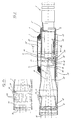
- the rifle scope has an outer tube 1, in which a component carrier 2 is arranged.
- a component carrier 2 is arranged in the component carrier 2 in the component carrier 2 in the component carrier 2 in the component carrier 2 is a coaxial channel 3 with the crosshair trained target 4 provided in channel 3 .
- channel 3 the reversing system of the riflescope is also arranged.
- the target 4 and the reversal system are preferably in an inner tube 5, which is inserted into the channel 3 is.
- the eyepiece 6 connects to the inner tube 5.
- the Reversal system can be for a constant or a variable Magnification.
- the target 4 is arranged in the focal plane 7 of the lens 8. ( Figure 4)
- the optical axis of the visual telescopic beam path is designated 10. Between the radial plane with the Target 4 and the lens 8 are in the see-through direction the rifle scope in the visual rifle scope beam path, that is, the beam 9 of the lens 8, one behind the other three beam splitters 11 to 11 each formed as prisms 13 are provided, each having a reflection surface 14 to 16 exhibit.
- the beam splitters 11 to 13 can also be used Be formed mirror.
- the beam splitter 13 with the reflection surface 16 is used for Mirroring the beam path 17 of the laser transmitter 18 in the visual rifle scope 9 in the direction of the lens 8.
- the transmitter 18 is on one, d. H. in the Drawing lower side, on component carrier 2 on the target mark side attached by the reflective surface 16, the optical Axis of the transmitter 18 parallel to the optical axis 10 of the rifle scope.
- a mirror 19 Through a mirror 19, a Prism or the like optical deflection or auxiliary device the laser beam emitted by the transmitter 18 becomes Reflecting surface 16 of the beam splitter 13 reflects.
- the Transmitter 18 is formed by a transmitter diode.
- the beam splitter 12 with the reflection surface 15 is used for Mirroring the beam path 20 of the targeted, not shown reflected, received via the lens 8 Radiation to the laser receiver 21.
- the receiver 21 is aligned perpendicular to the optical axis 10 and on the opposite of the transmitter 18, that is in the Drawing upper side, attached to component carrier 2.
- the Receiver 21 is formed by a photodiode.
- the reflection surfaces 15 and 16 of the beam splitters 12 and 13 are arranged so that the beam paths 17 and 20 of the Transmitter 18 and receiver 21 coaxial with the optical axis 10 of the rifle scope.
- the lens 8 forms thus the lens for the laser transmitter 18 and the Laser receiver 21.
- the arrangement of the reflection surface 16 of the laser receiver 18 in the viewing direction of the rifle scope the reflection surface 15 for the laser receiver 21 forms the beam path 17 of the transmitter 18 one to the optical axis 10 coaxial cone of rays from the coaxial cone of rays the beam path 20 of the laser receiver 21 is surrounded.
- the beam splitter 11 with the reflection surface 14 is used for Mirroring a preferably designed as a digital display Distance indicator 22 in the visual telescopic beam path towards eyepiece 6.
- the mirrored runs Beam path 23 of the optical display 22 parallel to optical display 10 of the riflescope, in the drawing is shifted down so that the visual display 22 not the view of the central area of the Target 4 affected.
- the optical distance indicator 22 is on the component carrier 2 attached to the side to which the beam path 23 is offset is, according to the drawing on the lower side.
- the optical distance indicator 22 emits light in the long wave Range of visible light, i.e. with a wavelength z. B. more than 0.65 microns.
- the reflection surface 14 is therefore formed by a dichroic coating that they are the long-wave light of the distance indicator 22 z. B. with a reflectance of e.g. 50% partially reflected and for visible light with a wavelength of less than 0.65 ⁇ m a transmittance of approx. 100%.
- the image plane of the beam path 23 of the distance indicator 22 lies in the plane of the target mark 4, that is to say the image plane 7 of the lens 8.
- the component carrier 2 has one square cross section. On the outer surfaces of the Component carrier 2, boards 27 to 30 are attached. For connection the boards 27 to 30 are plug connections 31 to 34 provided.
- the board 27 represents the base board.
- the board 28 has the control electronics for the laser transmitter 18 on, the board 29 the control electronics for the laser receiver 21 and the board 30 the evaluation electronics of the laser range finder.
- the energy source is powered by batteries 35 or equivalent Accumulators formed, which are arranged on the outer tube 1 are. Furthermore, is on the underside of the outer tube 1 Mounting rail 36 is provided with which the telescopic sight on the rifle, not shown, is attached.
- This adjustment device has a movable relative to the rifle, optical part between the target 4 and the Light entry side 38 of the rifle scope.
- this optical part is through the entire Objective 8 formed, which is arranged in an inner tube 37 is, which with a not shown in the drawing Articulation on the light entry side is mounted on the outer tube 1.
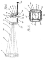
- FIG. 2a A variant of the adjusting device is shown in FIG. 2a.
- a partial lens of the objective 8 in an annular cage 40 in the see-through direction placed in front of the rest of the lens, which are located in a ring 41 fastened to the outer tube 1.
- the cage 40 is connected to the ring 41 via spring bars 42 connected.
- the adjusting spindle 39 and the not shown vertical adjustment spindles engage cage 40.
- the outer housing apart from the expanded cylindrical portion that receives the lens 8, corresponding to the component carrier 2 rectangular.
- the power source is under the cover 43.
- the adjustment button 44 for the threaded spindle 39 1 can be seen, the adjustment knob for this vertical adjustment spindle covered.
- the push button 45 which is preferably attached to the left side of the outer tube 1 the laser rangefinder, including the optical distance indicator 22 from the shooter e.g. be operated with the thumb of the left hand.
Landscapes
- Physics & Mathematics (AREA)
- Optics & Photonics (AREA)
- Astronomy & Astrophysics (AREA)
- General Physics & Mathematics (AREA)
- Engineering & Computer Science (AREA)
- General Engineering & Computer Science (AREA)
- Telescopes (AREA)
- Aiming, Guidance, Guns With A Light Source, Armor, Camouflage, And Targets (AREA)
- Crystals, And After-Treatments Of Crystals (AREA)
- Optical Radar Systems And Details Thereof (AREA)
- Optical Communication System (AREA)
Claims (13)
- Lunette de visée pour armes à feu avec un repère de visée (4), un appareil pour régler le repère de visée sur le point d'impact et un appareil télémétrique à laser pour la cible avec un émetteur laser (18) et un récepteur laser (21), caractérisée en ce que l'objectif (8) de la lunette de visée forme, par intégration de la trajectoire de faisceau (17) de l'émetteur laser (8) et de la trajectoire de faisceau (20) du récepteur laser (21) dans la trajectoire de faisceau visuelle (9) de la lunette de visée, simultanément l'objectif pour l'émetteur laser (18) et le récepteur laser (21), et en ce que l'appareil de réglage du repère de visée (4) sur le point d'impact présente une partie optique déplaçable par rapport au repère de visée et se situant entre le repère de visée (4) et le côté d'incidence de la lumière (38) de la lunette de visée.
- Lunette de visée selon la revendication 1, caractérisée en ce que l'intégration de la trajectoire de faisceau (17) de l'émetteur laser (8) et de la trajectoire de faisceau (20) du récepteur laser (21) dans la trajectoire de faisceau visuelle (9) de la lunette de visée se fait entre l'objectif (8) et le repère de visée (4).
- Lunette de visée selon la revendication 1 ou 2, caractérisée en ce que, pour intégrer la trajectoire de faisceau (17) de l'émetteur laser (18) et la trajectoire de faisceau (20) du récepteur laser (21) dans la trajectoire de faisceau visuelle (9) de la lunette de visée, on agence respectivement une surface de réflexion (15, 16) réfléchissant sélectivement la lumière et laissant passer la lumière visible dans la trajectoire de faisceau visuelle (9) de la lunette de visée.
- Lunette de visée selon l'une quelconque des revendications 1 à 3, caractérisée en ce que la trajectoire de faisceau (17) de l'émetteur laser (18) et la trajectoire de faisceau (20) du récepteur laser (21) sont intégrées coaxialement dans la trajectoire de faisceau visuelle (9) de la lunette de visée.
- Lunette de visée selon la revendication 3 ou 4, caractérisée en ce que les deux surfaces de réflexion (15, 16) sont aménagées l'une derrière l'autre dans la trajectoire de faisceau visuelle (9) de la lunette de visée.
- Lunette de visée selon la revendication 1, caractérisée en ce que la partie optique de l'appareil de réglage déplaçable par rapport à l'arme est formée par au moins une lentille partielle de l'objectif (8).
- Lunette de visée selon la revendication 6, caractérisée en ce que, pour déplacer la ou au moins une lentille partielle de l'objectif (8), il est prévu deux axes de réglage (39) aménagés selon un angle mutuel.
- Lunette de visée selon la revendication 1, caractérisée en ce qu'il est prévu un affichage de distance optique (22) qui est raccordé à l'électronique d'exploitation de l'appareil télémétrique à laser et peut être intégré dans la trajectoire de faisceau visuelle (9) de la lunette de visée.
- Lunette de visée selon la revendication 8, caractérisée en ce que l'affichage de distance optique (22) émet de la lumière dans la zone de grandes longueurs d'onde de la lumière visible et il est prévu, pour intégrer l'affichage de distance optique (22) dans la trajectoire de faisceau visuelle (9) de la lunette de visée, une surface de réflexion (14) réfléchissant de manière sélective la lumière de l'affichage de distance optique (22).
- Lunette de visée selon l'une quelconque des revendications précédentes, caractérisée en ce qu'il est prévu un porte-composants (2) aménagé dans le tube externe (1) de la lunette de visée pour recevoir l'émetteur laser (18), le récepteur laser (21), l'électronique de commande et d'exploitation de l'appareil télémétrique à laser ainsi que le système d'inversion et l'oculaire (6) de la lunette de visée.
- Lunette de visée selon la revendication 10, caractérisée en ce que l'électronique de l'appareil télémétrique à laser est aménagée sur des platines (27 à 30), le porte-composants (2) présente une section transversale prismatique et les platines (27 à 30) sont aménagées sur la surface externe du porte-composants (2).
- Lunette de visée selon la revendication 10 ou 11, caractérisée en ce que le porte-composants (2) présente un canal coaxial (3) pour recevoir le système d'inversion.
- Lunette de visée selon l'une quelconque des revendications précédentes, caractérisée en ce qu'il est prévu une mémoire dans laquelle les données balistiques de l'arme et de la munition peuvent être mémorisées et l'appareil de réglage du repère de visée (4) peut être commandé par au moins un moteur de réglage, qui peut être commandé par l'électronique d'exploitation de l'appareil télémétrique à laser et par les données balistiques mémorisées dans la mémoire.
Applications Claiming Priority (2)
| Application Number | Priority Date | Filing Date | Title |
|---|---|---|---|
| DE4438955A DE4438955C2 (de) | 1994-10-31 | 1994-10-31 | Zielfernrohr |
| DE4438955 | 1994-10-31 |
Publications (3)
| Publication Number | Publication Date |
|---|---|
| EP0709705A2 EP0709705A2 (fr) | 1996-05-01 |
| EP0709705A3 EP0709705A3 (fr) | 1999-06-09 |
| EP0709705B1 true EP0709705B1 (fr) | 2003-01-22 |
Family
ID=6532192
Family Applications (1)
| Application Number | Title | Priority Date | Filing Date |
|---|---|---|---|
| EP95117092A Expired - Lifetime EP0709705B1 (fr) | 1994-10-31 | 1995-10-30 | Lunette de visée |
Country Status (4)
| Country | Link |
|---|---|
| US (1) | US5771623A (fr) |
| EP (1) | EP0709705B1 (fr) |
| AT (1) | ATE231625T1 (fr) |
| DE (2) | DE4438955C2 (fr) |
Cited By (3)
| Publication number | Priority date | Publication date | Assignee | Title |
|---|---|---|---|---|
| EP2295926A1 (fr) | 2009-09-03 | 2011-03-16 | Carl Zeiss Sports Optics GmbH | Lunette de visée |
| EP2813795A1 (fr) | 2013-06-12 | 2014-12-17 | Swarovski Optik Kg | Instrument de télé-optique |
| EP3516448B1 (fr) | 2016-09-22 | 2022-08-24 | Lightforce USA, Inc., D/B/A/ Nightforce Optics | Système de projection d'informations de ciblage optique pour des endoscopes de visée de système d'arme et systèmes associés |
Families Citing this family (92)
| Publication number | Priority date | Publication date | Assignee | Title |
|---|---|---|---|---|
| DE29615815U1 (de) | 1996-09-12 | 1996-11-21 | Hensoldt AG, 35576 Wetzlar | Zielfernrohr |
| US7856750B2 (en) * | 1997-12-08 | 2010-12-28 | Horus Vision Llc | Apparatus and method for calculating aiming point information |
| US5920995A (en) | 1997-12-08 | 1999-07-13 | Sammut; Dennis J. | Gunsight and reticle therefor |
| USD415546S (en) | 1998-10-21 | 1999-10-19 | Leupold & Stevens, Inc. | Telescopic sight mounting rack |
| US6269581B1 (en) * | 1999-04-12 | 2001-08-07 | John Groh | Range compensating rifle scope |
| AT407202B (de) | 1999-06-10 | 2001-01-25 | Perger Andreas Dr | Kombinierte fernrohr- und entfernungsmessvorrichtung |
| CN1120993C (zh) * | 1999-08-27 | 2003-09-10 | 武汉长江光电有限公司 | 快速校准瞄准镜 |
| US6311424B1 (en) * | 1999-09-28 | 2001-11-06 | Peter G. Burke | Telescope for weapons and other applications |
| US20050213962A1 (en) * | 2000-03-29 | 2005-09-29 | Gordon Terry J | Firearm Scope Method and Apparatus for Improving Firing Accuracy |
| ES2279906T5 (es) * | 2002-03-01 | 2012-04-13 | Carl Zeiss Optronics Gmbh | Mira telescópica con dispositivo de visualización interno |
| US7624528B1 (en) | 2002-05-18 | 2009-12-01 | John Curtis Bell | Scope adjustment method and apparatus |
| US9310165B2 (en) | 2002-05-18 | 2016-04-12 | John Curtis Bell | Projectile sighting and launching control system |
| US6886287B1 (en) * | 2002-05-18 | 2005-05-03 | John Curtis Bell | Scope adjustment method and apparatus |
| US8468930B1 (en) | 2002-05-18 | 2013-06-25 | John Curtis Bell | Scope adjustment method and apparatus |
| US20040231220A1 (en) * | 2003-05-23 | 2004-11-25 | Mccormick Patrick | Trajectory compensating riflescope |
| US7603804B2 (en) * | 2003-11-04 | 2009-10-20 | Leupold & Stevens, Inc. | Ballistic reticle for projectile weapon aiming systems and method of aiming |
| US7230684B2 (en) | 2004-03-10 | 2007-06-12 | Raytheon Company | Method and apparatus for range finding with a single aperture |
| US7516571B2 (en) * | 2004-05-12 | 2009-04-14 | Scrogin Andrew D | Infrared range-finding and compensating scope for use with a projectile firing device |
| TWI273279B (en) * | 2004-06-17 | 2007-02-11 | Asia Optical Co Inc | Laser sight and method for assembling the same |
| DE102004034267A1 (de) * | 2004-07-15 | 2006-02-09 | Hensoldt Ag | System zur Ermittlung und/oder Einstellung einer Elevationskorrektur |
| DE102004048907A1 (de) | 2004-10-06 | 2006-04-27 | S.A.T. Swiss Arms Technology Ag | Visiervorrichtung für eine Schußwaffe und Schußwaffe mit einer Montagemöglichkeit für eine Visiervorrichtung |
| DE102005007916A1 (de) * | 2005-02-10 | 2006-08-17 | Hensoldt Ag | Zielfernrohr mit einem Entfernungsmesser |
| TWI259268B (en) * | 2005-02-17 | 2006-08-01 | Asia Optical Co Inc | Method for optical receiver to eliminate coaxial internal reflection signal and optoelectronic system employing the same |
| TWI429875B (zh) | 2005-11-01 | 2014-03-11 | Leupold & Stevens Inc | 用於傾斜射擊之彈道測距方法及系統 |
| US7599045B2 (en) * | 2006-01-25 | 2009-10-06 | Asia Optical Co., Inc. | Method for eliminating internal reflection of range finding system and range finding system applying the same |
| US7574825B2 (en) * | 2006-02-02 | 2009-08-18 | Nikon Inc. | Gun sight with continuously measuring rangefinder |
| US7703679B1 (en) | 2006-02-03 | 2010-04-27 | Burris Corporation | Trajectory compensating sighting device systems and methods |
| US8201741B2 (en) * | 2006-02-03 | 2012-06-19 | Burris Corporation | Trajectory compensating sighting device systems and methods |
| US7428796B1 (en) * | 2006-03-06 | 2008-09-30 | Raytheon Company | Method and apparatus for using a lens to enhance illumination of a reticle |
| US7877921B1 (en) * | 2006-03-06 | 2011-02-01 | Raytheon Company | Method and apparatus for combining light from two sources to illuminate a reticle |
| TW200736658A (en) * | 2006-03-24 | 2007-10-01 | Asia Optical Co Inc | Display device for telescope system |
| USD564001S1 (en) * | 2006-07-10 | 2008-03-11 | Swarovski Optik-Kg | Telescopic sight |
| US8713845B1 (en) | 2006-08-01 | 2014-05-06 | Raytheon Canada Limited | Method and apparatus for efficiently collecting radiation |
| US7827723B1 (en) | 2006-10-20 | 2010-11-09 | Leupold & Stevens, Inc. | Lateral de-centering of riflescope objective for aiming adjustment |
| US7821708B2 (en) * | 2007-10-24 | 2010-10-26 | Raytheon Company | Method and apparatus for illuminating a reticle |
| TWI356156B (en) * | 2008-03-10 | 2012-01-11 | Asia Optical Co Inc | Laser sight |
| WO2012141810A1 (fr) | 2011-03-03 | 2012-10-18 | Faro Technologies, Inc. | Appareil et procédé pour cible |
| US9482755B2 (en) | 2008-11-17 | 2016-11-01 | Faro Technologies, Inc. | Measurement system having air temperature compensation between a target and a laser tracker |
| WO2010132831A1 (fr) | 2009-05-15 | 2010-11-18 | Dennis Sammut | Appareil et procédé pour calculer des informations de point de visée |
| DE102009026618A1 (de) * | 2009-05-29 | 2010-12-02 | Hilti Aktiengesellschaft | Lasergerät zur elektrooptischen Distanzmessung |
| US8659749B2 (en) * | 2009-08-07 | 2014-02-25 | Faro Technologies, Inc. | Absolute distance meter with optical switch |
| US20110167708A1 (en) * | 2010-01-12 | 2011-07-14 | Carson Cheng | Rubber Armored Rifle Scope with Integrated External Laser Sight |
| US8619265B2 (en) | 2011-03-14 | 2013-12-31 | Faro Technologies, Inc. | Automatic measurement of dimensional data with a laser tracker |
| US9772394B2 (en) | 2010-04-21 | 2017-09-26 | Faro Technologies, Inc. | Method and apparatus for following an operator and locking onto a retroreflector with a laser tracker |
| US9377885B2 (en) | 2010-04-21 | 2016-06-28 | Faro Technologies, Inc. | Method and apparatus for locking onto a retroreflector with a laser tracker |
| US9400170B2 (en) | 2010-04-21 | 2016-07-26 | Faro Technologies, Inc. | Automatic measurement of dimensional data within an acceptance region by a laser tracker |
| US8336776B2 (en) | 2010-06-30 | 2012-12-25 | Trijicon, Inc. | Aiming system for weapon |
| US8172139B1 (en) | 2010-11-22 | 2012-05-08 | Bitterroot Advance Ballistics Research, LLC | Ballistic ranging methods and systems for inclined shooting |
| US8902408B2 (en) | 2011-02-14 | 2014-12-02 | Faro Technologies Inc. | Laser tracker used with six degree-of-freedom probe having separable spherical retroreflector |
| US9686532B2 (en) | 2011-04-15 | 2017-06-20 | Faro Technologies, Inc. | System and method of acquiring three-dimensional coordinates using multiple coordinate measurement devices |
| GB2504890A (en) | 2011-04-15 | 2014-02-12 | Faro Tech Inc | Enhanced position detector in laser tracker |
| US9482529B2 (en) | 2011-04-15 | 2016-11-01 | Faro Technologies, Inc. | Three-dimensional coordinate scanner and method of operation |
| US9164173B2 (en) | 2011-04-15 | 2015-10-20 | Faro Technologies, Inc. | Laser tracker that uses a fiber-optic coupler and an achromatic launch to align and collimate two wavelengths of light |
| USD688577S1 (en) | 2012-02-21 | 2013-08-27 | Faro Technologies, Inc. | Laser tracker |
| US8833655B2 (en) | 2011-05-26 | 2014-09-16 | Burris Corporation | Magnification compensating sighting systems and methods |
| US8327573B1 (en) * | 2011-06-10 | 2012-12-11 | Carson Cheng | Rifle scope with integrated laser sight |
| WO2013106280A1 (fr) | 2012-01-10 | 2013-07-18 | Horus Vision Llc | Appareil et procédé permettant de calculer des informations de point de visée |
| JP6099675B2 (ja) | 2012-01-27 | 2017-03-22 | ファロ テクノロジーズ インコーポレーテッド | バーコード識別による検査方法 |
| TWI633272B (zh) | 2012-02-04 | 2018-08-21 | 伯里斯公司 | 瞄準系統 |
| US9038901B2 (en) | 2012-02-15 | 2015-05-26 | Burris Company, Inc. | Optical device having windage measurement instruments |
| US9250036B2 (en) | 2012-03-05 | 2016-02-02 | Burris Company, Inc. | Optical device utilizing ballistic zoom and methods for sighting a target |
| AT513009B1 (de) * | 2012-06-11 | 2021-02-15 | Swarovski Optik Kg | Objektiv für ein Bildaufzeichnungsgerät |
| US9423213B2 (en) * | 2012-11-14 | 2016-08-23 | Lasermax Inc | Recoil spring guide mounted target marker |
| WO2014081781A1 (fr) * | 2012-11-20 | 2014-05-30 | Kruger Optical, Inc. | Lunette viseur à affichage oculaire de l'élévation et de la déviation due au vent |
| EP2929280B1 (fr) | 2012-12-05 | 2017-11-29 | Raytheon Company | Viseur optique à visée directe ayant un système laser intégré |
| US9500444B2 (en) | 2013-01-11 | 2016-11-22 | Hvrt. Corp. | Apparatus and method for calculating aiming point information |
| US9041914B2 (en) | 2013-03-15 | 2015-05-26 | Faro Technologies, Inc. | Three-dimensional coordinate scanner and method of operation |
| DE102013207852A1 (de) * | 2013-04-29 | 2014-11-13 | Carl Zeiss Sports Optics Gmbh | Fernoptisches Gerät |
| US9395174B2 (en) | 2014-06-27 | 2016-07-19 | Faro Technologies, Inc. | Determining retroreflector orientation by optimizing spatial fit |
| US9423215B2 (en) | 2014-11-26 | 2016-08-23 | Burris Corporation | Multi-turn elevation knob for optical device |
| US10415934B2 (en) | 2015-02-27 | 2019-09-17 | Burris Company, Inc. | Self-aligning optical sight mount |
| US10508882B2 (en) | 2015-03-23 | 2019-12-17 | Ronnie VALDEZ | Simulated hunting devices and methods |
| AT518962B1 (de) * | 2016-07-22 | 2021-02-15 | Swarovski Optik Kg | Fernoptische Vorrichtung mit einem Absehen |
| CA3052469A1 (fr) | 2017-02-06 | 2018-08-09 | Sheltered Wings, Inc. D/B/A Vortex Optics | Optique de visualisation a systeme d'affichage integre |
| US10393480B2 (en) * | 2017-05-16 | 2019-08-27 | Meopta U.S.A., Inc. | Target acquisition improvements using patterned dichroic coatings |
| WO2019060975A1 (fr) * | 2017-09-29 | 2019-04-04 | Raython Canada Limited | Système de visée optique intégré |
| US11675180B2 (en) | 2018-01-12 | 2023-06-13 | Sheltered Wings, Inc. | Viewing optic with an integrated display system |
| EP3769028B1 (fr) | 2018-03-20 | 2024-06-26 | Sheltered Wings, Inc. D/b/a/ Vortex Optics | Optique de visualisation avec une base ayant un module lumineux |
| IL278128B2 (en) | 2018-04-20 | 2026-04-01 | Sheltered Wings Inc D/B/A Vortex Optics | Optical sight featuring an active dial for direct focusing |
| MX2021001512A (es) | 2018-08-08 | 2021-07-02 | Sheltered Wings Inc D/B/A Vortex Optics | Sistema de pantalla para una óptica de visualizacion. |
| AU2019388605A1 (en) | 2018-09-04 | 2021-02-18 | Hvrt Corp. | Reticles, methods of use and manufacture |
| KR20250148619A (ko) | 2019-01-18 | 2025-10-14 | 쉘터드 윙스, 인크. 디/비/에이 보텍스 옵틱스 | 라운드 카운터 시스템을 구비하는 시야 광학체 |
| US11448482B1 (en) * | 2019-05-15 | 2022-09-20 | Gary Keith Robb | Firearm light accessory for brightness control |
| US12468168B2 (en) | 2020-05-05 | 2025-11-11 | Sheltered Wings, Inc. | Reticle for a viewing optic |
| JP7723009B2 (ja) | 2020-05-05 | 2025-08-13 | シェルタード ウィングス インコーポレイテッド | イネーブラインターフェースを有する観察光学機器 |
| US11882813B2 (en) | 2020-10-15 | 2024-01-30 | Ronnie A Valdez | Wildlife tracking system |
| IL316402A (en) | 2022-04-25 | 2024-12-01 | Sheltered Wings Inc D/B/A Vortex Optics | Optical sight projection operator |
| DE102022205197B3 (de) * | 2022-05-24 | 2023-11-16 | Carl Zeiss Ag | Tragbares optisches Beobachtungsgerät |
| USD1092676S1 (en) * | 2023-11-20 | 2025-09-09 | Raytheon Canada Ltd. | Optical sight battery cap section |
| USD1093536S1 (en) * | 2023-11-20 | 2025-09-16 | Raytheon Canada Ltd. | Optical sight |
| USD1092675S1 (en) * | 2023-11-20 | 2025-09-09 | Raytheon Canada Ltd. | Optical sight knob |
| USD1092677S1 (en) * | 2023-11-20 | 2025-09-09 | Raytheon Canada Ltd. | Optical sight base |
Family Cites Families (14)
| Publication number | Priority date | Publication date | Assignee | Title |
|---|---|---|---|---|
| FR2414184A1 (fr) * | 1978-01-06 | 1979-08-03 | Sopelem | Dispositif de conduite de tir |
| EP0036099A1 (fr) * | 1980-03-15 | 1981-09-23 | Firma Carl Zeiss | Une combinaison de miroir et prisme pour l'harmonisation des axes optiques |
| JPS5834420A (ja) * | 1981-08-26 | 1983-02-28 | Tech Res & Dev Inst Of Japan Def Agency | 光学装置 |
| US4395096A (en) * | 1981-10-13 | 1983-07-26 | Leupold & Stevens, Inc. | Variable magnification telescopic sight having reticle centering mount |
| DE3208814C2 (de) * | 1982-03-11 | 1985-04-18 | D. Swarovski & Co., Wattens, Tirol | Zielfernrohr |
| AT389003B (de) * | 1984-01-25 | 1989-10-10 | Swarovski Optik Kg | Optische zieleinrichtung |
| FR2566109B1 (fr) * | 1984-06-15 | 1991-08-30 | Sfim | Ensemble de visee optique, de designation et de poursuite d'objectif |
| JPH03163511A (ja) * | 1989-11-22 | 1991-07-15 | Tokyo Sukoopu:Kk | 可視レザー光ライフルスコープ |
| US5052801A (en) * | 1989-12-19 | 1991-10-01 | Damocles Engineering, Inc. | Compact laser-assisted weapon sight |
| FR2656079B1 (fr) * | 1989-12-20 | 1994-05-06 | Etat Francais Delegue Armement | Lunette episcopique modulable et reconfigurable. |
| US5092670A (en) * | 1990-01-17 | 1992-03-03 | Preston Howard J | Automatic focusing system for use with a motion picture camera |
| KR940011331B1 (ko) * | 1992-03-18 | 1994-12-05 | 한국과학기술원 | 비선형 결정을 이용한 레이저 거리 측정기 |
| DE4218118C2 (de) * | 1992-06-02 | 2001-03-08 | Wolfgang Heller | Zielfernrohr |
| DE4222642A1 (de) * | 1992-07-10 | 1994-01-13 | Bodenseewerk Geraetetech | Bilderfassende Sensoreinheit |
-
1994
- 1994-10-31 DE DE4438955A patent/DE4438955C2/de not_active Expired - Fee Related
-
1995
- 1995-10-30 AT AT95117092T patent/ATE231625T1/de active
- 1995-10-30 DE DE59510539T patent/DE59510539D1/de not_active Expired - Lifetime
- 1995-10-30 EP EP95117092A patent/EP0709705B1/fr not_active Expired - Lifetime
- 1995-10-31 US US08/550,666 patent/US5771623A/en not_active Expired - Lifetime
Cited By (5)
| Publication number | Priority date | Publication date | Assignee | Title |
|---|---|---|---|---|
| EP2295926A1 (fr) | 2009-09-03 | 2011-03-16 | Carl Zeiss Sports Optics GmbH | Lunette de visée |
| DE102009039851A1 (de) | 2009-09-03 | 2011-05-12 | Carl Zeiss Sports Optics Gmbh | Zielfernrohr |
| EP2813795A1 (fr) | 2013-06-12 | 2014-12-17 | Swarovski Optik Kg | Instrument de télé-optique |
| US9488825B2 (en) | 2013-06-12 | 2016-11-08 | Swarovski-Optik Kg. | Long-range optical device |
| EP3516448B1 (fr) | 2016-09-22 | 2022-08-24 | Lightforce USA, Inc., D/B/A/ Nightforce Optics | Système de projection d'informations de ciblage optique pour des endoscopes de visée de système d'arme et systèmes associés |
Also Published As
| Publication number | Publication date |
|---|---|
| EP0709705A3 (fr) | 1999-06-09 |
| DE4438955A1 (de) | 1996-05-02 |
| DE4438955C2 (de) | 1996-09-26 |
| DE59510539D1 (de) | 2003-02-27 |
| EP0709705A2 (fr) | 1996-05-01 |
| ATE231625T1 (de) | 2003-02-15 |
| US5771623A (en) | 1998-06-30 |
Similar Documents
| Publication | Publication Date | Title |
|---|---|---|
| EP0709705B1 (fr) | Lunette de visée | |
| EP1848952B1 (fr) | Lunette de visee pourvue d'un telemetre | |
| AT407202B (de) | Kombinierte fernrohr- und entfernungsmessvorrichtung | |
| DE69626292T2 (de) | System für tag- und nachtsicht | |
| EP2238407B9 (fr) | Appareil d'observation equipe d'un telemetre | |
| EP1542052B1 (fr) | Binoculaire avec télémètre laser intégré | |
| DE2208838C1 (de) | Fernrohranordnung | |
| CH633638A5 (de) | Rundblickperiskop mit umschaltbarer tagsicht- und waermebild-optik. | |
| DE102007006710B3 (de) | Suchkopf für einen zielsuchenden Flugkörper | |
| DE2426785C3 (de) | Vorrichtung zum Ausrichten der zwei optischen Achsen einer kombinierten Zielfernrohr/IR-Goniometer-Anlage | |
| DE1132742B (de) | Zielfernrohr | |
| EP1688761B1 (fr) | Procédé et dispositif destinés à la découverte de systèmes optiques dans une zone de terrain | |
| DE3325755A1 (de) | Nachtkampf-zielhilfe fuer panzerabwehr-handwaffen | |
| DE102004054182C5 (de) | Binokulares Fernglas mit integriertem Laser-Entfernungsmesser | |
| EP2435852B1 (fr) | Système optique de visée | |
| EP1875150B1 (fr) | Dispositif d'alignement et procede pour aligner un axe d'un simulateur de tir sur la ligne de mire d'une arme | |
| DE3011316C2 (fr) | ||
| EP0189001A1 (fr) | Procédé et dispositif pour l'alignement de l'axe du canon d'une arme à feu | |
| DE10122935B4 (de) | Vermessungsinstrument mit optischem Entfernungsmesser | |
| DE102007022833A1 (de) | Modularer Entfernungsmesser zur universellen Adaption an vorhandene Zieleinrichtungen | |
| DE3234289A1 (de) | Zieleinrichtung fuer eine handfeuerwaffe | |
| EP2587210A2 (fr) | Appareil d'ajustement et agencement d'ajustement pour moyen de visée sur des armes, notamment des armes de poing | |
| WO1994019658A1 (fr) | Telemetre electro-optique adaptable a un systeme de vision nocturne | |
| DD261849A1 (de) | Elektrooptischer entfernungsmesser | |
| AT406804B (de) | Opto-elektronisches messverfahren |
Legal Events
| Date | Code | Title | Description |
|---|---|---|---|
| PUAI | Public reference made under article 153(3) epc to a published international application that has entered the european phase |
Free format text: ORIGINAL CODE: 0009012 |
|
| AK | Designated contracting states |
Kind code of ref document: A2 Designated state(s): AT BE CH DE FR GB IT LI SE |
|
| PUAL | Search report despatched |
Free format text: ORIGINAL CODE: 0009013 |
|
| AK | Designated contracting states |
Kind code of ref document: A3 Designated state(s): AT BE CH DE FR GB IT LI SE |
|
| RIC1 | Information provided on ipc code assigned before grant |
Free format text: 6G 02B 23/00 A, 6G 02B 23/10 B, 6F 41G 3/06 B, 6F 41G 3/32 B |
|
| 17P | Request for examination filed |
Effective date: 19990922 |
|
| GRAG | Despatch of communication of intention to grant |
Free format text: ORIGINAL CODE: EPIDOS AGRA |
|
| 17Q | First examination report despatched |
Effective date: 20020121 |
|
| GRAG | Despatch of communication of intention to grant |
Free format text: ORIGINAL CODE: EPIDOS AGRA |
|
| GRAH | Despatch of communication of intention to grant a patent |
Free format text: ORIGINAL CODE: EPIDOS IGRA |
|
| GRAH | Despatch of communication of intention to grant a patent |
Free format text: ORIGINAL CODE: EPIDOS IGRA |
|
| GRAA | (expected) grant |
Free format text: ORIGINAL CODE: 0009210 |
|
| AK | Designated contracting states |
Kind code of ref document: B1 Designated state(s): AT BE CH DE FR GB IT LI SE |
|
| REG | Reference to a national code |
Ref country code: GB Ref legal event code: FG4D Free format text: NOT ENGLISH |
|
| REG | Reference to a national code |
Ref country code: CH Ref legal event code: NV Representative=s name: ISLER & PEDRAZZINI AG Ref country code: CH Ref legal event code: EP |
|
| GBT | Gb: translation of ep patent filed (gb section 77(6)(a)/1977) |
Effective date: 20030122 |
|
| REF | Corresponds to: |
Ref document number: 59510539 Country of ref document: DE Date of ref document: 20030227 Kind code of ref document: P |
|
| PG25 | Lapsed in a contracting state [announced via postgrant information from national office to epo] |
Ref country code: SE Free format text: LAPSE BECAUSE OF FAILURE TO SUBMIT A TRANSLATION OF THE DESCRIPTION OR TO PAY THE FEE WITHIN THE PRESCRIBED TIME-LIMIT Effective date: 20030422 |
|
| ET | Fr: translation filed | ||
| PG25 | Lapsed in a contracting state [announced via postgrant information from national office to epo] |
Ref country code: BE Free format text: LAPSE BECAUSE OF NON-PAYMENT OF DUE FEES Effective date: 20031031 |
|
| PLBE | No opposition filed within time limit |
Free format text: ORIGINAL CODE: 0009261 |
|
| STAA | Information on the status of an ep patent application or granted ep patent |
Free format text: STATUS: NO OPPOSITION FILED WITHIN TIME LIMIT |
|
| 26N | No opposition filed |
Effective date: 20031023 |
|
| BERE | Be: lapsed |
Owner name: *SWAROVSKI OPTIK K.G. Effective date: 20031031 |
|
| REG | Reference to a national code |
Ref country code: CH Ref legal event code: PCAR Free format text: ISLER & PEDRAZZINI AG;POSTFACH 1772;8027 ZUERICH (CH) |
|
| PGFP | Annual fee paid to national office [announced via postgrant information from national office to epo] |
Ref country code: GB Payment date: 20101021 Year of fee payment: 16 |
|
| PGFP | Annual fee paid to national office [announced via postgrant information from national office to epo] |
Ref country code: CH Payment date: 20111025 Year of fee payment: 17 |
|
| PGFP | Annual fee paid to national office [announced via postgrant information from national office to epo] |
Ref country code: FR Payment date: 20121113 Year of fee payment: 18 |
|
| PGFP | Annual fee paid to national office [announced via postgrant information from national office to epo] |
Ref country code: IT Payment date: 20121026 Year of fee payment: 18 |
|
| REG | Reference to a national code |
Ref country code: CH Ref legal event code: PL |
|
| GBPC | Gb: european patent ceased through non-payment of renewal fee |
Effective date: 20121030 |
|
| PG25 | Lapsed in a contracting state [announced via postgrant information from national office to epo] |
Ref country code: LI Free format text: LAPSE BECAUSE OF NON-PAYMENT OF DUE FEES Effective date: 20121031 Ref country code: GB Free format text: LAPSE BECAUSE OF NON-PAYMENT OF DUE FEES Effective date: 20121030 Ref country code: CH Free format text: LAPSE BECAUSE OF NON-PAYMENT OF DUE FEES Effective date: 20121031 |
|
| PGFP | Annual fee paid to national office [announced via postgrant information from national office to epo] |
Ref country code: AT Payment date: 20131021 Year of fee payment: 19 |
|
| REG | Reference to a national code |
Ref country code: FR Ref legal event code: ST Effective date: 20140630 |
|
| PG25 | Lapsed in a contracting state [announced via postgrant information from national office to epo] |
Ref country code: FR Free format text: LAPSE BECAUSE OF NON-PAYMENT OF DUE FEES Effective date: 20131031 Ref country code: IT Free format text: LAPSE BECAUSE OF NON-PAYMENT OF DUE FEES Effective date: 20131030 |
|
| PGFP | Annual fee paid to national office [announced via postgrant information from national office to epo] |
Ref country code: DE Payment date: 20141127 Year of fee payment: 20 |
|
| REG | Reference to a national code |
Ref country code: AT Ref legal event code: MM01 Ref document number: 231625 Country of ref document: AT Kind code of ref document: T Effective date: 20141030 |
|
| PG25 | Lapsed in a contracting state [announced via postgrant information from national office to epo] |
Ref country code: AT Free format text: LAPSE BECAUSE OF NON-PAYMENT OF DUE FEES Effective date: 20141030 |
|
| REG | Reference to a national code |
Ref country code: DE Ref legal event code: R071 Ref document number: 59510539 Country of ref document: DE |