EP0709749A1 - Fixiervorrichtung und Fixierverfahren - Google Patents
Fixiervorrichtung und Fixierverfahren Download PDFInfo
- Publication number
- EP0709749A1 EP0709749A1 EP95114313A EP95114313A EP0709749A1 EP 0709749 A1 EP0709749 A1 EP 0709749A1 EP 95114313 A EP95114313 A EP 95114313A EP 95114313 A EP95114313 A EP 95114313A EP 0709749 A1 EP0709749 A1 EP 0709749A1
- Authority
- EP
- European Patent Office
- Prior art keywords
- fluorine containing
- roller
- fixing
- silicone oil
- oil
- Prior art date
- Legal status (The legal status is an assumption and is not a legal conclusion. Google has not performed a legal analysis and makes no representation as to the accuracy of the status listed.)
- Granted
Links
Images

Classifications
-
- G—PHYSICS
- G03—PHOTOGRAPHY; CINEMATOGRAPHY; ANALOGOUS TECHNIQUES USING WAVES OTHER THAN OPTICAL WAVES; ELECTROGRAPHY; HOLOGRAPHY
- G03G—ELECTROGRAPHY; ELECTROPHOTOGRAPHY; MAGNETOGRAPHY
- G03G15/00—Apparatus for electrographic processes using a charge pattern
- G03G15/20—Apparatus for electrographic processes using a charge pattern for fixing, e.g. by using heat
- G03G15/2003—Apparatus for electrographic processes using a charge pattern for fixing, e.g. by using heat using heat
- G03G15/2014—Apparatus for electrographic processes using a charge pattern for fixing, e.g. by using heat using heat using contact heat
- G03G15/2053—Structural details of heat elements, e.g. structure of roller or belt, eddy current, induction heating
- G03G15/2057—Structural details of heat elements, e.g. structure of roller or belt, eddy current, induction heating relating to the chemical composition of the heat element and layers thereof
-
- G—PHYSICS
- G03—PHOTOGRAPHY; CINEMATOGRAPHY; ANALOGOUS TECHNIQUES USING WAVES OTHER THAN OPTICAL WAVES; ELECTROGRAPHY; HOLOGRAPHY
- G03G—ELECTROGRAPHY; ELECTROPHOTOGRAPHY; MAGNETOGRAPHY
- G03G15/00—Apparatus for electrographic processes using a charge pattern
- G03G15/20—Apparatus for electrographic processes using a charge pattern for fixing, e.g. by using heat
- G03G15/2003—Apparatus for electrographic processes using a charge pattern for fixing, e.g. by using heat using heat
- G03G15/2014—Apparatus for electrographic processes using a charge pattern for fixing, e.g. by using heat using heat using contact heat
- G03G15/2017—Structural details of the fixing unit in general, e.g. cooling means, heat shielding means
- G03G15/2025—Structural details of the fixing unit in general, e.g. cooling means, heat shielding means with special means for lubricating and/or cleaning the fixing unit, e.g. applying offset preventing fluid
-
- G—PHYSICS
- G03—PHOTOGRAPHY; CINEMATOGRAPHY; ANALOGOUS TECHNIQUES USING WAVES OTHER THAN OPTICAL WAVES; ELECTROGRAPHY; HOLOGRAPHY
- G03G—ELECTROGRAPHY; ELECTROPHOTOGRAPHY; MAGNETOGRAPHY
- G03G2215/00—Apparatus for electrophotographic processes
- G03G2215/20—Details of the fixing device or porcess
- G03G2215/2093—Release agent handling devices
Definitions
- the present invention relates to a fixing device and a method of fixing, and more particularly, to an improvement of a fixing device and a method of fixing used in an image forming apparatus or the like.
- a fixing device of a heat roller type wherein a heat roller is employed.
- resins serving as developing agents (toner) are fused and are caused to pass through a pair of rollers to be fixed on a recording medium such as a sheet of paper as toner images.
- silicone rubber has been used as a material for the surface of a fixing roller.
- releasability between a fixing roller and a recording medium is poor when the silicone robber is used as it is. Therefore, there has been employed a method wherein silicon oil composed of alkylpolysiloxane such as dimethylpolysiloxane is coated on the surface of a roller by an oil supply device.
- dimethyl silicone oil to be coated on the surface of silicone rubber requires a coating amount of not less than 8 x 10 ⁇ 6 [cc/cm2].
- Durability of a rubber roller in terms of oil-swelling and abrasion is about tens of thousands of copies.
- An oil coating device requires some device such as an oil tank having a capacity for oil of hundreds cc.
- silicone rubber when silicone rubber is coated on the surface of a fixing roller, its durability is low.
- silicone oil when silicone oil is used as oil to be coated, an affinity for the roller surface is low, and accordingly, a large amount of oil is needed for coating on the roller surface uniformly. As a result of a large amount of oil needed, a life of a device for supplying oil to be coated (for example, an oil pad or the like) is shortened. In some cases, an oil tank or an oil supply device which is expensive is needed.
- the present invention has been achieved with the foregoing as a background, and its object is to provide a fixing device and a method of fixing wherein durability of a fixing roller is high and a life of a device for supplying oil to be coated can be lengthened by supplying oil having high surface wettability with the surface of a fixing roller.
- a pair of fixing rollers heating toner images and fixing them on a recording medium wherein at least one roller coming into contact with toner is provided thereon with fluorine containing resins and a device for coating fluorine containing silicone oil on the surface of the aforesaid fluorine containing resins at a coating amount of not more than 1.4 x 10 ⁇ 6 [cc/cm2].
- a pair of fixing rollers heating toner images and fixing them on a recording medium wherein at least one roller coming into contact with toner is provided thereon with fluorine containing resins, and fluorine containing silicone oil to be coated on the surface of the aforesaid fluorine containing resins has a structural unit represented by the following formula.
- X represents saturated hydrocarbon having 1 - 4 carbon atoms or an aryl group
- Rf represents fluoroalkyl group having 2 - 10 carbon atoms
- n represents an integer ranging from 1 to 4.
- Rf represents preferably Z - (CF2)m - wherein Z represents hydrogen or a fluorine atom, and m represents an integer ranging from 2 to 10.
- fluorine containing resin that forms the aforesaid fluorine containing resin layer is any of PTFE, PFA and FEP.
- a pair of fixing rollers heating toner images and fixing them on a recording medium wherein at least one roller coming into contact with toner is provided thereon with fluorine containing resins, and fluorine containing silicone oil is coated on the surface of the aforesaid fluorine containing resins at a coating amount of not more than 1.4 x 10 ⁇ 6 [cc/cm2].
- a pair of fixing rollers heating toner images and fixing them on a recording medium wherein at least one roller coming into contact with toner is provided thereon with fluorine containing resins, and fluorine containing silicone oil having a structural unit represented by the following formula is coated on the surface of the aforesaid fluorine containing resins.
- X represents saturated hydrocarbon having 1 - 4 carbon atoms or an aryl group
- Rf represents fluoroalkyl group having 2 - 10 carbon atoms
- n represents an integer ranging from 1 to 4.
- Rf represents preferably Z - (CF2)m - wherein Z represents hydrogen or a fluorine atom, and m represents an integer ranging from 2 to 10.
- fluorine containing resin that forms the aforesaid fluorine containing resin layer is any of PTFE, PFA and FEP.
- a pair of fixing rollers heating toner images and fixing them on a recording medium wherein at least one roller coming into contact with toner is provided thereon with fluorine containing resins and a device for coating fluorine containing silicone oil on the surface of the aforesaid fluorine containing resins at a coating amount of not more than 1.4 x 10 ⁇ 6 [cc/cm2].
- durability of a fixing roller is high, and a life of a device for supplying oil to be coated can be lengthened by supplying oil having high surface wettability with the surface of a fixing roller.
- a pair of fixing rollers heating toner images and fixing them on a recording medium wherein at least one roller coming into contact with toner is provided thereon with fluorine containing resins, and fluorine containing silicone oil to be coated on the surface of the aforesaid fluorine containing resins has a structural unit represented by the following formula.
- X represents saturated hydrocarbon having 1 - 4 carbon atoms or an aryl group
- Rf represents fluoroalkyl group having 2 - 10 carbon atoms
- n represents an integer ranging from 1 to 4. Owing to this, durability of a fixing roller is high, and a life of a device for supplying oil to be coated can be lengthened by supplying oil having high surface wettability with the surface of a fixing roller.
- the number of fluorine is related to a great effect for uniform adhesion of oil to a fixing roller that is covered with fluorocarbon resins.
- the number of carbon atoms of alkyl fluoride is 2 - 10 and a part which is directly linked to a silicon atom is a methylene chain.
- a range of 2 - 8 for the number of carbon atoms is more appropriate.
- a terminal group it is preferable that it is a carbon fluoride group linked to a saturated hydrocarbon group or a methylene group such as a methyl group or a ethyl group.
- silicone oil used in the invention needs to have the aforementioned repeating unit, it may also be of a construction as a copolymer with dimethyl silicon, phenylmethyl silicon or diphenyl silicon.
- this construction as a copolymer 20 mole % or more of a construction of fluorine containing silicone oil of the invention needs to be included.
- fluorine containing silicone oil does not show its effect, but effects of other construction are exhibited remarkably.
- Fluorine containing silicone oil of the invention needs to be liquid substance having appropriate viscosity when it is used.
- a coefficient of viscosity of fluorine containing silicone oil of the invention at 25°C is 20 - 1000 cs, and its appropriate range is 100 - 500 cs.
- This viscosity represents dynamic viscosity and it can be measured practically by an Ubbelohde viscometer. This viscosity can be controlled by adjusting a degree of polymerization of fluorine containing silicone oil of the invention.
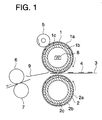
- Fig. 1 is a diagram showing an example of a principle and constitution of the invention.
- Fig. 2 is an illustration of comparison of affinity between dimethyl silicone oil and fluorine containing silicone oil.
- Fig. 1 is a diagram showing an example of a principle and constitution of the invention.
- 1 represents an upper fixing roller
- 2 represents a lower fixing roller that form a counterpart to the upper fixing roller
- the numeral 1a is a fluorocarbon resin layer forming a superficial layer of the upper fixing roller
- the numeral 1b is an elastic layer positioned under the fluorocarbon resin layer 1a
- 1c is a core metal that is provided inside the elastic layer 1b and serves as a core of the roller.
- the fluorocarbon resin layer 1a PFA (ethylenetetrafluorite-perfluoroalkoxyethylene copolymer), for example, is used.
- PFA resin has a principal chain of polyfluoroethylene and, - OR group (R is perfluoroalkyl group) is linked to a side chain.
- OR group R is perfluoroalkyl group
- fluorocarbon resin PTFE (polytetrafluoroethylene), FEP (polyfluoroethylenepropylene copolymer) and others are used in addition to the foregoing. These PFA, PTFE and FEP have characteristics that durability is extremely high compared with fluorocarbon resins of other kinds.
- a thickness of the fluorocarbon resin layer 1a a thickness of about 50 ⁇ m, for example, is used.
- the elastic layer 1b silicone rubber, for example, is used, and its thickness used is 1 mm, for example, and its hardness used is about JIS-A 13°.
- the core metal 1c aluminum, for example, is used and as a thickness of the core metal used is about 3 mm, for example.
- the numeral 8 is a heating means provided inside the upper heating roller 1.
- a halogen lamp heater for example, is used and its output used is about 850 W, for example, so that the surface of the fixing roller may be heated up to about 200°C.
- the lower fixing roller 2 is the same as the upper fixing roller 1 in terms of constitution.
- the numeral 2a is a fluorocarbon resin layer forming a superficial layer of the lower fixing roller 2
- the numeral 2b is an elastic layer positioned under the fluorocarbon resin layer 2a
- 2c is a core metal that is provided inside the elastic layer 2b and serves as a core of the roller.
- the fluorocarbon resin layer 2a PFA, for example, is used, and its thickness used is about 50 ⁇ m.
- silicone rubber for example, is used, and its thickness used is 1 mm, for example, and its hardness used is about JIS-A 13°.
- the core metal 2c steel, for example, is used and its thickness used is about 3 mm, for example.
- the thickness of the elastic layers 1b and 2b mentioned above is 0.5 - 5.0 mm, toner images can be fixed uniformly on recording medium 3, which is convenient, because uniform fixing of toner images is necessary for full color fixing that is required for high image quality.
- the rollers 1 and 2 mentioned above rotate respectively in the direction shown in the figure.
- the fluorocarbon resin layer forming the superficial layer on each of the fixing rollers 1 and 2 has only to be provided at least on the roller (upper fixing roller 1) coming into contact with toner images, and the lower fixing roller 2 does not necessarily need to be provided with the fluorocarbon resin layer.
- the numeral 3 is a recording medium such as a recording sheet and a transparency sheet, and 4 is a toner image formed on recording medium 3.
- the numeral 5 is an oil coating roller as a system (means) to coat fluorine containing silicone oil on the surface of upper fixing roller 1. This oil coating means does not need to be of a form of a roller as the coating roller 5 is, but it may take any form provided that it has a system to coat oil on the surface of upper fixing roller 1 uniformly.
- the numerals 6 and 7 represent a sheet-ejecting roller that ejects recording medium 3 on which an image has been fixed.
- the numeral 9 is a guide that leads the recording medium 3 ejected from the fixing rollers 1 and 2 to the sheet-ejecting rollers 6 and 7. Movements of an apparatus constituted as in the foregoing will be explained as follows.
- a toner image obtained by a developing unit through development of an electrostatic latent image formed on a photoreceptor is transferred onto recording medium 3 which is conveyed to a fixing unit by a conveyance system.
- This toner image 4 may be either a monochromatic toner image or a color toner image.
- upper fixing roller 1, lower fixing roller 2 and oil coating roller 5 are rotated in the directions shown in the figure.
- toner image 4 thereon is subjected to heat-fusion at around 200°C and then is fixed on the recording medium 3.
- durability of each of the fixing rollers is higher than that of a roller made of material of silicone rubber because a superficial layer of the fixing roller is made of a fluorocarbon resin layer.
- the use of the aforementioned PFA, PTFE or FEP as a fluorocarbon resin layer makes the durability to be extremely high.
- the recording medium 3 on which images have been fixed is conveyed to the sheet-ejecting rollers 6 and 7 through guide 9 to be ejected.
- fluorine containing silicone oil is constantly supplied to the upper fixing roller 1 from oil coating roller 5.
- This fluorine containing oil has high affinity with fluorocarbon resin layer 1a and thereby is coated uniformly and entirely on the surface of the upper fixing roller 1. Therefore, releasability for the recording medium 3 to be released from the fixing rollers 1 and 2 is greatly improved.
- Figs. 2(a) and 2(b) show an illustration of comparison of affinity between dimethyl silicone oil and fluorine containing silicone oil.
- Fig. 2(a) shows how dimethyl silicone oil sticks to the surface of a fluorocarbon resin layer
- Fig. 2(b) shows how fluorine containing silicone oil sticks to the surface of a fluorocarbon resin layer.
- contact angle ⁇ formed between dimethyl silicone oil 10 and a fluorocarbon resin layer 1a is about 30° - 40°
- contact angle ⁇ formed between fluorine containing silicone oil 11 and a fluorocarbon resin layer 1a is 10° or less.
- a small contact angle means that affinity is high (surface tension is small) and oil tends to spread over the fluorocarbon resin layer 1a. This further means that wettability of fluorine containing silicone oil is higher and thereby broader area can be coated with the same amount of oil. Accordingly, less amount of oil to be coated is required for fluorine containing silicone oil, resulting in longer life of a coating oil supply system.
- the surface tension at 20 dyn/cm of this fluorine containing silicone oil is a preferable condition for it to have high affinity.
- a coating amount of 1.4 x 10⁶ [cc/cm2] or less for fluorine containing silicone oil is a preferable condition for supplying coating oil on the surface of a fixing roller uniformly and entirely, for lessening an influence of excessive oil on an image, and for lengthening life of a coating oil supply system.
- Chemicals 7 and 8 shown below represent concrete structural examples of fluorine containing silicone oil shown in Formula (1). Thirteen kinds of structures of fluorine containing silicone oil ranging from (1) to (13) are shown. In this case, a and b represent an integer of not less than one, and a and b preferably represent an integer of 10 - 2000, and more preferable range thereof is 100 - 1000. Effects of the invention will be explained as follows, referring to experimental examples. Table 1 shows examples of conditions for the experiments made by the use of a fixing device shown in Fig. 1.
- the number of experimental devices in total was thirteen including those for experimental examples 1 through 13.
- a fluorocarbon resin layer, a coating amount of oil and silicone oil (parenthesized numbers in the table correspond to those in Chemicals 1 and 2) all shown in the table were used for each experimental example.
- Silicone oil (14) in this case is fluorine silicone oil having on its side chain a trifluoropropyl group which is sold from Dow Corning Co., Ltd. in a trade name of FS-1265.
- Fluorine silicone oil (15) has the following structure.
- lower fixing roller 2 (see Fig. 1) of the fixing device used was one structured with a silicone rubber roller.
- Table 2 shows that no change was observed on both upper roller and lower roller for Experimental examples 1 - 7, while for Experimental examples 8 - 10, both upper roller and lower roller showed slight scratches which, however, were not problematic in practical use.
- Experimental example 11 no change was observed on both upper and lower rollers.
- Experimental examples 12 - 13 both upper roller and lower roller showed scratches thereon.
- Table 3 above shows that no offset problem was observed for Experimental examples 1 - 7, and an occurrence of the offset problem was observed for Experimental examples 8 - 10. For Experimental example 11, an offset problem occurred excessively, while for Experimental examples 12 and 13, an occurrence of the offset problem was observed.
- a pair of fixing rollers heating toner images and fixing them on a recording medium wherein at least one roller coming into contact with toner is provided thereon with fluorine containing resins and a device for coating fluorine containing silicone oil on the surface of the aforesaid fluorine containing resins at a coating amount of not more than 1.4 x 10 ⁇ 6 [cc/cm2].
- a fluorine containing resin layer is used as a superficial layer of a fixing roller, and fluorine containing silicone oil is used as coating oil, and thereby it is possible to realize a fixing device and a method of fixing wherein durability of fixing rollers is high and life of a coating oil supply system can be extended, which results in an extremely great effect in practical use.
Landscapes
- Physics & Mathematics (AREA)
- General Physics & Mathematics (AREA)
- Fixing For Electrophotography (AREA)
Applications Claiming Priority (3)
| Application Number | Priority Date | Filing Date | Title |
|---|---|---|---|
| JP23528094 | 1994-09-29 | ||
| JP23528094A JP3369008B2 (ja) | 1994-09-29 | 1994-09-29 | 定着装置 |
| JP235280/94 | 1994-09-29 |
Publications (2)
| Publication Number | Publication Date |
|---|---|
| EP0709749A1 true EP0709749A1 (de) | 1996-05-01 |
| EP0709749B1 EP0709749B1 (de) | 2000-07-12 |
Family
ID=16983768
Family Applications (1)
| Application Number | Title | Priority Date | Filing Date |
|---|---|---|---|
| EP95114313A Expired - Lifetime EP0709749B1 (de) | 1994-09-29 | 1995-09-12 | Fixiervorrichtung und Fixierverfahren |
Country Status (4)
| Country | Link |
|---|---|
| US (1) | US5716747A (de) |
| EP (1) | EP0709749B1 (de) |
| JP (1) | JP3369008B2 (de) |
| DE (1) | DE69517913T2 (de) |
Cited By (1)
| Publication number | Priority date | Publication date | Assignee | Title |
|---|---|---|---|---|
| EP1460490A1 (de) | 2003-03-18 | 2004-09-22 | Xerox Corporation | Fluorosilikontrennmitel für Fixierelemente, die Fluoreleastomere enthalten |
Families Citing this family (21)
| Publication number | Priority date | Publication date | Assignee | Title |
|---|---|---|---|---|
| US6808814B2 (en) * | 2003-03-18 | 2004-10-26 | Xerox Corporation | Blended fluorosilicone release agent for polymeric fuser members |
| US6808815B2 (en) * | 2003-03-18 | 2004-10-26 | Xerox Corporation | Blended fluorosilicone release agent for silicone fuser members |
| US7291399B2 (en) * | 2003-08-30 | 2007-11-06 | Xerox Corporation | Fuser fluid compositions |
| US20050266166A1 (en) * | 2004-05-26 | 2005-12-01 | Halsey Glenn T | Method for coating paper machines |
| DE102005001350B4 (de) * | 2005-01-11 | 2007-03-01 | Schulze-Hagenest, Detlef, Dr. | Selbstreinigende Fixierwalzen |
| US7381514B2 (en) * | 2005-02-08 | 2008-06-03 | Xerox Corporation | Stabilization of fluorinated silicone fuser release agents using mercapto functional silicones |
| US7744960B2 (en) * | 2005-05-23 | 2010-06-29 | Xerox Corporation | Process for coating fluoroelastomer fuser member using fluorinated surfactant |
| US7485344B2 (en) * | 2005-05-23 | 2009-02-03 | Xerox Corporation | Process for coating fluoroelastomer fuser member layer using blend of two different fluorinated surfactants |
| US7704560B2 (en) * | 2005-05-23 | 2010-04-27 | Xerox Corporation | Process for coating fluoroelastomer fuser member using blend of deflocculant material and fluorine-containing polysiloxane additive |
| US7651740B2 (en) * | 2005-05-23 | 2010-01-26 | Xerox Corporation | Process for coating fluoroelastomer fuser member using fluorinated surfactant and fluroinated polysiloxane additive blend |
| US7641942B2 (en) * | 2005-05-23 | 2010-01-05 | Xerox Corporation | Process for coating fluoroelastomer fuser member using fluorine-containing additive |
| US7242900B2 (en) * | 2005-06-02 | 2007-07-10 | Xerox Corporation | Oil-less fuser member |
| US7494756B2 (en) | 2005-07-05 | 2009-02-24 | Xerox Corporation | Release fluid compositions |
| US7462395B2 (en) * | 2006-02-15 | 2008-12-09 | Xerox Corporation | Fuser member |
| US20080057433A1 (en) * | 2006-08-30 | 2008-03-06 | Xerox Corporation | Adhesive primer |
| US7807015B2 (en) * | 2006-09-18 | 2010-10-05 | Xerox Corporation | Adhesion promoter |
| US8980388B2 (en) * | 2008-01-18 | 2015-03-17 | Xerox Corporation | Use of silane promoter to modify pressure sensitive adhesive for use in pressure seal mailers printed on IGEN3 |
| US8080318B2 (en) * | 2008-03-07 | 2011-12-20 | Xerox Corporation | Self-healing fuser and fixing members |
| US8318302B2 (en) * | 2008-03-12 | 2012-11-27 | Xerox Corporation | Fuser member release layer having nano-size copper metal particles |
| US8135324B2 (en) * | 2009-03-09 | 2012-03-13 | Xerox Corporation | Fuser member and methods of making thereof |
| CN111936939B (zh) * | 2018-03-22 | 2022-08-16 | 佳能株式会社 | 定影构件、定影装置和电子照相图像形成设备 |
Citations (8)
| Publication number | Priority date | Publication date | Assignee | Title |
|---|---|---|---|---|
| JPS5118544A (en) | 1974-07-30 | 1976-02-14 | Ricoh Kk | Tonaagazono teichakuhoho |
| JPS52124338A (en) | 1976-04-12 | 1977-10-19 | Ricoh Co Ltd | Fixing process |
| EP0018140A1 (de) * | 1979-04-04 | 1980-10-29 | Xerox Corporation | Bauteil, Verfahren und System zum Schmelzfixieren von Tonerbildern auf einem Träger |
| EP0077991A2 (de) * | 1981-10-22 | 1983-05-04 | EASTMAN KODAK COMPANY (a New Jersey corporation) | Mehrschicht-Fixiervorrichtung und Herstellungsverfahren |
| JPS62187372A (ja) * | 1986-02-13 | 1987-08-15 | Matsushita Electric Ind Co Ltd | 定着装置 |
| EP0441114A1 (de) * | 1990-01-06 | 1991-08-14 | Fuji Xerox Co., Ltd. | Elastische Fixierrolle mit ausgezeichneter Ablöseeigenschaft |
| WO1993021567A1 (de) * | 1992-04-16 | 1993-10-28 | Siemens Nixdorf Informationssysteme Aktiengesellschaft | Wärme-druckfixierstation für eine elektrofotografische druckeinrichtung sowie ein verfahren zu deren herstellung |
| EP0640888A1 (de) * | 1993-08-27 | 1995-03-01 | Asahi Glass Company Ltd. | Schmutzabweisendes Öl für eine Thermofixierwalze |
-
1994
- 1994-09-29 JP JP23528094A patent/JP3369008B2/ja not_active Expired - Fee Related
-
1995
- 1995-09-07 US US08/524,611 patent/US5716747A/en not_active Expired - Lifetime
- 1995-09-12 DE DE69517913T patent/DE69517913T2/de not_active Expired - Fee Related
- 1995-09-12 EP EP95114313A patent/EP0709749B1/de not_active Expired - Lifetime
Patent Citations (9)
| Publication number | Priority date | Publication date | Assignee | Title |
|---|---|---|---|---|
| JPS5118544A (en) | 1974-07-30 | 1976-02-14 | Ricoh Kk | Tonaagazono teichakuhoho |
| JPS52124338A (en) | 1976-04-12 | 1977-10-19 | Ricoh Co Ltd | Fixing process |
| DE2716203A1 (de) * | 1976-04-12 | 1977-10-27 | Ricoh Kk | Fixiervorrichtung |
| EP0018140A1 (de) * | 1979-04-04 | 1980-10-29 | Xerox Corporation | Bauteil, Verfahren und System zum Schmelzfixieren von Tonerbildern auf einem Träger |
| EP0077991A2 (de) * | 1981-10-22 | 1983-05-04 | EASTMAN KODAK COMPANY (a New Jersey corporation) | Mehrschicht-Fixiervorrichtung und Herstellungsverfahren |
| JPS62187372A (ja) * | 1986-02-13 | 1987-08-15 | Matsushita Electric Ind Co Ltd | 定着装置 |
| EP0441114A1 (de) * | 1990-01-06 | 1991-08-14 | Fuji Xerox Co., Ltd. | Elastische Fixierrolle mit ausgezeichneter Ablöseeigenschaft |
| WO1993021567A1 (de) * | 1992-04-16 | 1993-10-28 | Siemens Nixdorf Informationssysteme Aktiengesellschaft | Wärme-druckfixierstation für eine elektrofotografische druckeinrichtung sowie ein verfahren zu deren herstellung |
| EP0640888A1 (de) * | 1993-08-27 | 1995-03-01 | Asahi Glass Company Ltd. | Schmutzabweisendes Öl für eine Thermofixierwalze |
Non-Patent Citations (1)
| Title |
|---|
| PATENT ABSTRACTS OF JAPAN vol. 12, no. 42 (P - 663)<2889> 6 February 1988 (1988-02-06) * |
Cited By (2)
| Publication number | Priority date | Publication date | Assignee | Title |
|---|---|---|---|---|
| EP1460490A1 (de) | 2003-03-18 | 2004-09-22 | Xerox Corporation | Fluorosilikontrennmitel für Fixierelemente, die Fluoreleastomere enthalten |
| US6830819B2 (en) | 2003-03-18 | 2004-12-14 | Xerox Corporation | Fluorosilicone release agent for fluoroelastomer fuser members |
Also Published As
| Publication number | Publication date |
|---|---|
| JP3369008B2 (ja) | 2003-01-20 |
| JPH0895408A (ja) | 1996-04-12 |
| EP0709749B1 (de) | 2000-07-12 |
| US5716747A (en) | 1998-02-10 |
| DE69517913T2 (de) | 2000-12-07 |
| DE69517913D1 (de) | 2000-08-17 |
Similar Documents
| Publication | Publication Date | Title |
|---|---|---|
| EP0709749B1 (de) | Fixiervorrichtung und Fixierverfahren | |
| US4515884A (en) | Fusing system with unblended silicone oil | |
| US4375505A (en) | Fuser member | |
| KR100708277B1 (ko) | 정착장치 및 화상형성장치 | |
| US5636012A (en) | Toner image fixing device | |
| CN100492216C (zh) | 使用氟碳树脂涂覆部件的成像设备 | |
| US6099673A (en) | Method of coating fuser members | |
| US5679462A (en) | Fixing apparatus | |
| CA2460775C (en) | Blended fluorosilicone release agent for polymeric fuser members | |
| EP0784247A2 (de) | Fixiervorrichtung | |
| EP1046961B1 (de) | Ölauftragsrolle für ein Bilderzeugungsgerät | |
| US6954607B2 (en) | Fusing apparatus and method for liquid toner electrophotography using multiple stations having different prefusing and fusing temperatures | |
| CN1484580A (zh) | 隔离剂组合物 | |
| JP2003149976A (ja) | 定着用回転体、加圧用回転体および定着装置 | |
| JP2006030528A (ja) | 無端状ベルト搬送体および画像形成装置 | |
| JP2992224B2 (ja) | 電子写真定着装置 | |
| CA2308823C (en) | Polythiophene filled xerographic component coatings | |
| JPH0876625A (ja) | シリコーン及びバイトンの定着ローラ | |
| JP3559074B2 (ja) | 定着装置 | |
| JP3607819B2 (ja) | 電子写真定着装置 | |
| US6953615B2 (en) | Polythiophene xerographic component coatings | |
| JP4040197B2 (ja) | 弾性ローラの製造方法 | |
| US20160252853A1 (en) | Fixing member, fixing device, and image-forming apparatus | |
| US6363236B1 (en) | Release oil regulating blade, fixing device, and image-forming apparatus | |
| JPH10301431A (ja) | 定着装置および画像形成方法 |
Legal Events
| Date | Code | Title | Description |
|---|---|---|---|
| PUAI | Public reference made under article 153(3) epc to a published international application that has entered the european phase |
Free format text: ORIGINAL CODE: 0009012 |
|
| 17P | Request for examination filed |
Effective date: 19960219 |
|
| AK | Designated contracting states |
Kind code of ref document: A1 Designated state(s): DE GB |
|
| 17Q | First examination report despatched |
Effective date: 19970212 |
|
| GRAG | Despatch of communication of intention to grant |
Free format text: ORIGINAL CODE: EPIDOS AGRA |
|
| GRAG | Despatch of communication of intention to grant |
Free format text: ORIGINAL CODE: EPIDOS AGRA |
|
| GRAH | Despatch of communication of intention to grant a patent |
Free format text: ORIGINAL CODE: EPIDOS IGRA |
|
| RBV | Designated contracting states (corrected) |
Designated state(s): DE GB |
|
| GRAH | Despatch of communication of intention to grant a patent |
Free format text: ORIGINAL CODE: EPIDOS IGRA |
|
| GRAA | (expected) grant |
Free format text: ORIGINAL CODE: 0009210 |
|
| AK | Designated contracting states |
Kind code of ref document: B1 Designated state(s): DE GB |
|
| REF | Corresponds to: |
Ref document number: 69517913 Country of ref document: DE Date of ref document: 20000817 |
|
| EN | Fr: translation not filed | ||
| PLBE | No opposition filed within time limit |
Free format text: ORIGINAL CODE: 0009261 |
|
| STAA | Information on the status of an ep patent application or granted ep patent |
Free format text: STATUS: NO OPPOSITION FILED WITHIN TIME LIMIT |
|
| 26N | No opposition filed | ||
| REG | Reference to a national code |
Ref country code: GB Ref legal event code: IF02 |
|
| PGFP | Annual fee paid to national office [announced via postgrant information from national office to epo] |
Ref country code: GB Payment date: 20030910 Year of fee payment: 9 |
|
| PGFP | Annual fee paid to national office [announced via postgrant information from national office to epo] |
Ref country code: DE Payment date: 20030925 Year of fee payment: 9 |
|
| PG25 | Lapsed in a contracting state [announced via postgrant information from national office to epo] |
Ref country code: GB Free format text: LAPSE BECAUSE OF NON-PAYMENT OF DUE FEES Effective date: 20040912 |
|
| PG25 | Lapsed in a contracting state [announced via postgrant information from national office to epo] |
Ref country code: DE Free format text: LAPSE BECAUSE OF NON-PAYMENT OF DUE FEES Effective date: 20050401 |
|
| GBPC | Gb: european patent ceased through non-payment of renewal fee |
Effective date: 20040912 |