EP0709750A1 - Reinigungsvorrichtung zur Entfernung von nicht übertragenem Toner - Google Patents
Reinigungsvorrichtung zur Entfernung von nicht übertragenem Toner Download PDFInfo
- Publication number
- EP0709750A1 EP0709750A1 EP95307758A EP95307758A EP0709750A1 EP 0709750 A1 EP0709750 A1 EP 0709750A1 EP 95307758 A EP95307758 A EP 95307758A EP 95307758 A EP95307758 A EP 95307758A EP 0709750 A1 EP0709750 A1 EP 0709750A1
- Authority
- EP
- European Patent Office
- Prior art keywords
- latent image
- holding member
- charge holding
- toner
- image charge
- Prior art date
- Legal status (The legal status is an assumption and is not a legal conclusion. Google has not performed a legal analysis and makes no representation as to the accuracy of the status listed.)
- Withdrawn
Links
- 238000004140 cleaning Methods 0.000 title claims abstract description 64
- 238000010438 heat treatment Methods 0.000 claims description 33
- 238000007599 discharging Methods 0.000 claims description 7
- 238000000034 method Methods 0.000 claims description 7
- 238000003825 pressing Methods 0.000 claims description 2
- 238000005452 bending Methods 0.000 claims 1
- 239000002245 particle Substances 0.000 description 16
- 230000000694 effects Effects 0.000 description 10
- 238000002474 experimental method Methods 0.000 description 9
- 230000010287 polarization Effects 0.000 description 8
- 238000007790 scraping Methods 0.000 description 7
- 229920000642 polymer Polymers 0.000 description 6
- 239000002033 PVDF binder Substances 0.000 description 5
- 229920002981 polyvinylidene fluoride Polymers 0.000 description 4
- 230000007423 decrease Effects 0.000 description 3
- 238000000151 deposition Methods 0.000 description 3
- 239000010419 fine particle Substances 0.000 description 3
- 238000012546 transfer Methods 0.000 description 3
- 230000003247 decreasing effect Effects 0.000 description 2
- 230000008021 deposition Effects 0.000 description 2
- 238000011161 development Methods 0.000 description 2
- 239000000843 powder Substances 0.000 description 2
- 230000005616 pyroelectricity Effects 0.000 description 2
- 229920002379 silicone rubber Polymers 0.000 description 2
- 239000004945 silicone rubber Substances 0.000 description 2
- 230000002269 spontaneous effect Effects 0.000 description 2
- XAGFODPZIPBFFR-UHFFFAOYSA-N aluminium Chemical compound [Al] XAGFODPZIPBFFR-UHFFFAOYSA-N 0.000 description 1
- 229910052782 aluminium Inorganic materials 0.000 description 1
- 238000013459 approach Methods 0.000 description 1
- 230000015572 biosynthetic process Effects 0.000 description 1
- 238000007664 blowing Methods 0.000 description 1
- 230000001419 dependent effect Effects 0.000 description 1
- 238000012423 maintenance Methods 0.000 description 1
- 238000006386 neutralization reaction Methods 0.000 description 1
- 230000005855 radiation Effects 0.000 description 1
- 239000007787 solid Substances 0.000 description 1
- 239000000126 substance Substances 0.000 description 1
Images


Classifications
-
- G—PHYSICS
- G03—PHOTOGRAPHY; CINEMATOGRAPHY; ANALOGOUS TECHNIQUES USING WAVES OTHER THAN OPTICAL WAVES; ELECTROGRAPHY; HOLOGRAPHY
- G03G—ELECTROGRAPHY; ELECTROPHOTOGRAPHY; MAGNETOGRAPHY
- G03G21/00—Arrangements not provided for by groups G03G13/00 - G03G19/00, e.g. cleaning, elimination of residual charge
- G03G21/0005—Arrangements not provided for by groups G03G13/00 - G03G19/00, e.g. cleaning, elimination of residual charge for removing solid developer or debris from the electrographic recording medium
-
- G—PHYSICS
- G03—PHOTOGRAPHY; CINEMATOGRAPHY; ANALOGOUS TECHNIQUES USING WAVES OTHER THAN OPTICAL WAVES; ELECTROGRAPHY; HOLOGRAPHY
- G03G—ELECTROGRAPHY; ELECTROPHOTOGRAPHY; MAGNETOGRAPHY
- G03G15/00—Apparatus for electrographic processes using a charge pattern
- G03G15/22—Apparatus for electrographic processes using a charge pattern involving the combination of more than one step according to groups G03G13/02 - G03G13/20
- G03G15/32—Apparatus for electrographic processes using a charge pattern involving the combination of more than one step according to groups G03G13/02 - G03G13/20 in which the charge pattern is formed dotwise, e.g. by a thermal head
Definitions
- the present invention relates to a cleaning device for removing non-transferred toner and, more particularly, to a cleaning device for removing non-transferred toner remaining on a latent image charge holding member in an image recording apparatus such as a printer, a facsimile system, or a copying machine.
- a cleaning device having the same structure as that of a cleaning device in an electrophotographic image recording apparatus is disclosed. That is, a cleaning device for mechanically scraping a charged marking particles (toner) from a latent image charge holding member with a blade or brush pressed against the latent image charge holding member is disclosed.
- a force exceeding the attraction between the charged marking particles and the latent image charge holding member must be applied to the charged marking particles attracted thereto with a blade or brush.
- charged marking particles used for image recording like a powder toner
- a powder toner is a mass of a fine particles each having a diameter of about 10 ⁇ m. These fine particles are firmly attracted to the latent image charge holding member with an electrostatic force. It is therefore not easily to completely remove many fine particles of the charged marking particles (to be referred to as a toner hereinafter) attracted to the latent image charge holding member. For this reason, toner tends to remain on the latent image charge holding member even after the member passes through the cleaning device. In the above known device, as the toner decreases in size and its shape approaches a spherical shape, the cleaning operation is made more difficult.
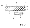
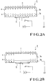
- the first embodiment shown in Figs. 1 to 2B includes a silicone rubber blade 2 and a cleaning case 3.
- the blade 2 scrapes toner T from a latent image charge holding member 1 having a pyroelectric layer la capable of holding polarization charges on its surface.
- the toner T is attracted to one surface of the latent image charge holding member 1 with an electrostatic force.
- the cleaning case 3 is used to store the toner T scraped by the blade 2.
- the blade 2 is pressed against the latent image charge holding member 1 with the elasticity of the silicone rubber.
- Reference numeral 1b denotes a conductive layer attached to the other surface of the pyroelectric layer 1a.
- the conductive layer 1b and the pyroelectric layer 1a constitute the latent image charge holding member 1 in the form of an endless belt.
- the latent image charge holding member 1 has a heater 5 in the form of a thick plate, which is a heating means disposed in contact with the conductive layer 1b and adapted to heat the pyroelectric layer 1a.
- the pyroelectric layer la of the latent image charge holding member 1 has polarization charges +e and -e on one surface and the other surface, respectively, upon spontaneous polarization of molecules.
- the toner T is attracted to the surface of the latent image charge holding member 1 with an electrostatic force acting between the toner and the polarization charges +e.
- the toner T can be easily removed from the latent image charge holding member 1 by heating the latent image charge holding member 1, and mechanically scraping the toner T from the latent image charge holding member 1 with the latent image charge holding member 1 or the like in a state wherein the attraction between the latent image charge holding member 1 and the toner T is reduced.
- the powder toner T was attracted to the entire surface of the latent image charge holding member 1, and the toner T was then removed while the heating temperature of the heater 5 was variously changed.
- the latent image charge holding member 1 a member obtained by depositing an aluminum film (Al film) as the conductive layer 1b on one surface of a PVDF (polyvinylidene fluoride) layer as the pyroelectric layer 1a was used.
- the toner T a fine spherical polymer toner with an average particle diameter of 5 ⁇ m was used as the toner T.
- the toner T was removed while the heating temperature of the heater 5 was changed to room temperature (25°C), 60°C, and 80°C.
- the heating temperature of the heater 5 was room temperature (25°C), i.e., the heater 5 generated no heat, a large amount of toner T remaining on the latent image charge holding member 1 after the member passed through the cleaning device was easily observed with the naked eye.
- the heating temperature of the heater 5 was 60°C
- the toner T could be removed to such an extent that the residual toner could not easily be observed with the naked eye. In observation with a microscope, the presence of a small amount of toner T was confirmed.
- the heating temperature of the heater 5 was 80°C
- the cleaning ability could be improved to a level at which the residual toner T could not easily be observed even with the microscope.
- the heating temperature needs to be lower than at least the Curie point of the pyroelectric layer 1a.
- the heating temperature is preferably set to be 80°C or less when PVDF is to be used, in consideration of quality maintenance.
- the image forming apparatus in Fig. 3 includes the above latent image charge holding member 1 in the form of an endless belt, a thermal head 14 for forming an electrostatic latent image, a dry type toner developing unit 15 for developing the electrostatic latent image, a transfer unit 16 as a transfer means for a recording member (recording paper) P, a fixing unit 17 for fixing the transferred toner T, a cleaning device 18 having the blade 2 and the heater 5 and serving to remove the unnecessary residual toner T, a discharging brush 19 for discharging unnecessary charges, and the like.
- the latent image charge holding member 1 a belt constituted by a film in an endless form was used.
- the film was made of two layers, i.e., the pyroelectric layer 1a (a PVDF layer having a thickness of about 30 ⁇ m) and the conductive layer 1b (an Al deposition film having a thickness of about 500 ⁇ ).
- the latent image charge holding member 1 was selectively heated by the thermal head 14 in accordance with an image signal, and a latent image was formed by using a pyroelectric effect. Thereafter, toner development was performed by using the toner developing unit 15.
- As the toner T a spherical polymer toner having an average particle diameter of 5 ⁇ m was used.
- the latent image charge holding member 1 having undergone development was superposed on the recording paper P as a recording member, and the toner T was electrostatically transferred onto the surface of the recording paper P. Thereafter, a toner image 20 was fixed onto the recording paper P by the fixing unit 17 using a heat roller. After the toner T was transferred onto the recording paper P, the latent image charge holding member 1 was conveyed to the latent image forming portion (thermal head) 14 again to execute the next latent image forming operation. Prior to this operation, removal of the non-transferred toner T remaining on the latent image charge holding member 1 and discharging (neutralization) of the latent image charge holding member 1 were performed by the cleaning device 18 and the discharging brush 19, respectively. In this experiment, this image recording operation was repeatedly performed a plurality of number of times.
- the toner T remains even after the latent image charge holding member 1 passes through the cleaning device 18. As a result, the toner T is transferred, as noise, onto the recording paper P when blank paper is output in even-numbered operations. The presence/absence of the residual toner depending on the transfer of the toner was checked by using the above phenomenon.
- the optimal heating temperature of the cleaning device 18 changes depending on the arrangement of the device upon receiving influences of various factors such as the mechanical scraping ability of the blade 2 and the shape of the toner T. For this reason, the heating temperatures are not limited to 45°C to 55°C.
- Fig. 4 shows the second embodiment of the present invention.
- the second embodiment in Fig. 4 is characterized in that a heating resistive element is incorporated, as a heater 12a, in a blade 12.
- the remaining arrangement of the second embodiment is the same as that of the embodiment in Fig. 1.
- the toner T a spherical polymer toner with an average particle diameter of 5 ⁇ m was used, similar to the embodiment in Fig. 1.
- the heating temperature of a heater 12a was changed to room temperature (25°C), 60°C, and 80°C, and the cleaning abilities at the respective temperatures were compared with each other. As a result, it was confirmed that the cleaning ability improved with a rise in heating temperature. More specifically, at room temperature (25°C), i.e., when the heater 12a generated no heat, since a sufficient cleaning ability was not obtained only with the blade 12, a large amount of toner T remaining on the latent image charge holding member 1 after the member passed through a cleaning device 18 could be easily observed with the naked eye.
- the heating temperature of the heater 12a When the heating temperature of the heater 12a was set to be 60°C, the residual toner T could not easily be observed with the naked eye. It was confirmed that the cleaning ability improved to such an extent that a small amount of residual toner T could be observed with a microscope. In addition, when the heating temperature of the heater 12a was set to be 80°C, it was confirmed that the cleaning ability improved to a level at which the residual toner T could not easily be observed even with the microscope.
- Fig. 5 shows the third embodiment of the present invention.
- a latent image charge holding member 1 is heated by a heater 5.
- the third embodiment includes an ultrasonic vibrator 22 instead of the blade 2 in Fig. 1.
- the remaining arrangement is the same as that of the embodiment in Fig. 1.
- the toner T was attracted to the entire surface of a latent image charge holding member 1 with an electrostatic force, and the toner T was then removed.
- a spherical polymer toner with an average particle diameter of 5 ⁇ m was used, similar to the embodiment in Fig. 1.
- the latent image charge holding member 1 was vibrated by the ultrasonic vibrator 22 while the member was heated by the heater 5, thereby shaking the toner T off the member.
- the latent image charge holding member 1 was only vibrated without being heated by the heater 5, the toner T attracted to the member could hardly be removed.
- the heating temperature of the heater 5 was gradually raised, the cleaning ability improved. At about 70°C, a perfect cleaning operation could be performed.
- the embodiment shown in Fig. 4 includes the heater 5 independently of the ultrasonic vibrator 22. It was, however, confirmed that the same effect as that described above could be obtained by using the ultrasonic vibrator 22 as a mechanical scraping means and heat generated by the ultrasonic vibrator 22 itself when it was continuously vibrated.
- heating means other techniques can be used as long as the same function as that described above can be obtained.
- a method of blowing hot air a method of heating with a laser, a method of performing radiation heating with a lamp, and the like are available.
- the mechanical removing means a method using a brush or a removing means using a magnetic force, if the toner T is a magnetic toner, may be used.
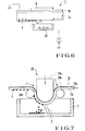
- Fig. 6 shows a cleaning device according to the fourth embodiment of the present invention.
- a latent image charge holding member 1 is heated by a heater 5.
- the fourth embodiment includes an electrostatic discharging unit 23 in place of the blade 2. The remaining arrangement is the same as that of the embodiment in Fig. 1.
- FIG. 7 shows a cleaning device according to the fifth embodiment of the present invention.
- a cleaning device 18 of the fifth embodiment shown in Fig. 7 includes a stress applying mechanism 24 for mechanically distorting a latent image charge holding member 10 having piezoelectricity, a blade 2 for mechanically removing a toner T, and a cleaning case 3 for storing the toner T scraped with the blade 2.
- a film made of two layers i.e., a pyroelectric layer 10a (a PVDF layer having a thickness of about 30 ⁇ m) as a piezoelectric layer and a conductive layer 10b (an Al deposition film having a thickness of about 500 ⁇ ) was used.
- This film has undergone a polarization process in such a manner that the spontaneous polarization on the pyroelectric layer 10a reduces, and the surface potential decreases upon application of a tension F in the direction indicated by reference symbol F in Fig. 7.
- the stress applying mechanism 24 is constituted by a press member 24a which comes into contact with the latent image charge holding member 10 as if crossing the member, and guide rollers 24b and 24c disposed on two sides of the press member 24a.
- the guide rollers 24b and 24c are disposed on two sides of the press member 24a through the latent image charge holding member 10.
- the latent image charge holding member 10 When the latent image charge holding member 10 is mechanically distorted, the oriented state of molecules can be changed as in the case wherein the pyroelectric effect is used. By using this, therefore, the polarization charges on the surface of the latent image charge holding member 10 can be reduced.
- the stress applying mechanism 24 mechanically distorts the latent image charge holding member 10 to reduce the attraction between the toner T and the latent image charge holding member 10, thereby allowing easy removal of the toner T from the latent image charge holding member 10.
- a substance having pyroelectricity also has piezoelectricity.
- the latent image charge holding member 10 having the pyroelectric layer 10a like the one in the embodiment in Fig. 1 is therefore used in such a manner that a pyroelectric effect is used for the formation of a latent image, and piezoelectricity is used for cleaning the non-transferred toner T to easily remove the toner T from the latent image charge holding member 10.
- the blade 2 is used as a scraping mechanism.
- the same effect as described above can be obtained by using a brush, ultrasonic vibrations, a magnetic force, or the like.
- a heater for heating the latent image charge holding member 10 may be used, together with the stress applying mechanism 24.
- an ultrasonic vibrator for vibrating the latent image charge holding member 10 while pressing it may be used. In this case, the blade 2 can be omitted.
- a PVDF layer having pyroelectricity has piezoelectricity as well.
- the fifth embodiment forms a latent image by using the pyroelectric effect, and removes non-transferred toner by using the piezoelectric effect.
- a cleaning device superior to the conventional cleaning devices, which can reliably remove the residual charged toner from the latent image charge holding member with high precision, thereby improving the overall reliability of the apparatus.
Landscapes
- Physics & Mathematics (AREA)
- General Physics & Mathematics (AREA)
- Cleaning In Electrography (AREA)
- Printers Or Recording Devices Using Electromagnetic And Radiation Means (AREA)
- Electrophotography Using Other Than Carlson'S Method (AREA)
Applications Claiming Priority (2)
| Application Number | Priority Date | Filing Date | Title |
|---|---|---|---|
| JP266854/94 | 1994-10-31 | ||
| JP6266854A JP2663883B2 (ja) | 1994-10-31 | 1994-10-31 | クリーニング装置 |
Publications (1)
| Publication Number | Publication Date |
|---|---|
| EP0709750A1 true EP0709750A1 (de) | 1996-05-01 |
Family
ID=17436591
Family Applications (1)
| Application Number | Title | Priority Date | Filing Date |
|---|---|---|---|
| EP95307758A Withdrawn EP0709750A1 (de) | 1994-10-31 | 1995-10-31 | Reinigungsvorrichtung zur Entfernung von nicht übertragenem Toner |
Country Status (3)
| Country | Link |
|---|---|
| US (1) | US5710966A (de) |
| EP (1) | EP0709750A1 (de) |
| JP (1) | JP2663883B2 (de) |
Cited By (1)
| Publication number | Priority date | Publication date | Assignee | Title |
|---|---|---|---|---|
| EP0816933A1 (de) * | 1996-06-24 | 1998-01-07 | Xerox Corporation | Xerographische Vorrichtung zum Aufladen und zur Übertragung |
Families Citing this family (5)
| Publication number | Priority date | Publication date | Assignee | Title |
|---|---|---|---|---|
| JPH11102121A (ja) * | 1997-09-29 | 1999-04-13 | Minolta Co Ltd | 画像形成装置 |
| US6073294A (en) * | 1998-12-22 | 2000-06-13 | Xerox Corporation | Cleaning brush using the pyroelectric effect |
| US6569256B1 (en) * | 2000-09-21 | 2003-05-27 | Intel Corporation | Removing toner from printed material |
| US6529702B2 (en) * | 2001-07-25 | 2003-03-04 | Xerox Corporation | Cleaning blade arranged with at least one heater and printer arranged with the same |
| DE60233777D1 (de) * | 2001-07-26 | 2009-11-05 | Canon Kk | Reinigungsvorrichtung und Bilderzeugungsgerät |
Citations (12)
| Publication number | Priority date | Publication date | Assignee | Title |
|---|---|---|---|---|
| US3824098A (en) | 1972-06-23 | 1974-07-16 | Bell Telephone Labor Inc | Pyroelectric copying device |
| US3935327A (en) | 1973-08-06 | 1976-01-27 | Minnesota Mining And Manufacturing Company | Copying using pyroelectric film |
| US4260243A (en) * | 1979-10-15 | 1981-04-07 | Pitney Bowes Inc. | Cleaning apparatus |
| JPS56158350A (en) | 1980-05-10 | 1981-12-07 | Nippon Telegr & Teleph Corp <Ntt> | Recording method |
| JPS60119575A (ja) | 1983-12-01 | 1985-06-27 | Canon Inc | 画像形成方法 |
| JPH01161370A (ja) | 1987-12-18 | 1989-06-26 | Toshiba Corp | 静電潜像の形成方法 |
| EP0323143A2 (de) * | 1987-12-28 | 1989-07-05 | Xerox Corporation | Elektronisches Farbdrucksystem mit Vibrationsentwicklung |
| JPH0233155A (ja) * | 1988-07-22 | 1990-02-02 | Canon Inc | 電子写真感光体 |
| EP0404491A2 (de) * | 1989-06-19 | 1990-12-27 | Xerox Corporation | Elektrostatisches Bilderzeugungsgerät |
| JPH03212658A (ja) | 1990-01-18 | 1991-09-18 | Matsushita Electric Ind Co Ltd | 画像形成装置 |
| EP0490642A2 (de) * | 1990-12-11 | 1992-06-17 | Xerox Corporation | Elektrostatographisches Bilderzeugungsgerät |
| US5185619A (en) | 1991-04-26 | 1993-02-09 | Xerox Corporation | Electrostatic printing method and apparatus employing a pyroelectric imaging member |
Family Cites Families (8)
| Publication number | Priority date | Publication date | Assignee | Title |
|---|---|---|---|---|
| US3879785A (en) * | 1973-04-27 | 1975-04-29 | Xerox Corp | Cleaning apparatus |
| US4111546A (en) * | 1976-08-26 | 1978-09-05 | Xerox Corporation | Ultrasonic cleaning apparatus for an electrostatographic reproducing machine |
| US5264903A (en) * | 1990-05-21 | 1993-11-23 | Ricoh Company, Ltd. | Cleaning unit with a cleaning member made of activated carbon fibers |
| US5065194A (en) * | 1990-05-29 | 1991-11-12 | Eastman Kodak Company | Piezo film cleaner |
| JP3214889B2 (ja) * | 1992-04-10 | 2001-10-02 | 株式会社リコー | 画像形成装置 |
| JPH05307346A (ja) * | 1992-04-29 | 1993-11-19 | Ricoh Co Ltd | 画像形成装置のクリーニング装置 |
| JPH06186885A (ja) * | 1992-12-21 | 1994-07-08 | Canon Inc | クリーニング装置及び画像形成装置 |
| US5282005A (en) * | 1993-01-13 | 1994-01-25 | Xerox Corporation | Cross process vibrational mode suppression in high frequency vibratory energy producing devices for electrophotographic imaging |
-
1994
- 1994-10-31 JP JP6266854A patent/JP2663883B2/ja not_active Expired - Fee Related
-
1995
- 1995-10-30 US US08/550,305 patent/US5710966A/en not_active Expired - Fee Related
- 1995-10-31 EP EP95307758A patent/EP0709750A1/de not_active Withdrawn
Patent Citations (13)
| Publication number | Priority date | Publication date | Assignee | Title |
|---|---|---|---|---|
| US3824098A (en) | 1972-06-23 | 1974-07-16 | Bell Telephone Labor Inc | Pyroelectric copying device |
| US3935327A (en) | 1973-08-06 | 1976-01-27 | Minnesota Mining And Manufacturing Company | Copying using pyroelectric film |
| US4260243A (en) * | 1979-10-15 | 1981-04-07 | Pitney Bowes Inc. | Cleaning apparatus |
| JPS56158350A (en) | 1980-05-10 | 1981-12-07 | Nippon Telegr & Teleph Corp <Ntt> | Recording method |
| JPS60119575A (ja) | 1983-12-01 | 1985-06-27 | Canon Inc | 画像形成方法 |
| JPH01161370A (ja) | 1987-12-18 | 1989-06-26 | Toshiba Corp | 静電潜像の形成方法 |
| EP0323143A2 (de) * | 1987-12-28 | 1989-07-05 | Xerox Corporation | Elektronisches Farbdrucksystem mit Vibrationsentwicklung |
| JPH0233155A (ja) * | 1988-07-22 | 1990-02-02 | Canon Inc | 電子写真感光体 |
| EP0404491A2 (de) * | 1989-06-19 | 1990-12-27 | Xerox Corporation | Elektrostatisches Bilderzeugungsgerät |
| JPH03212658A (ja) | 1990-01-18 | 1991-09-18 | Matsushita Electric Ind Co Ltd | 画像形成装置 |
| EP0490642A2 (de) * | 1990-12-11 | 1992-06-17 | Xerox Corporation | Elektrostatographisches Bilderzeugungsgerät |
| US5185619A (en) | 1991-04-26 | 1993-02-09 | Xerox Corporation | Electrostatic printing method and apparatus employing a pyroelectric imaging member |
| JPH05134506A (ja) | 1991-04-26 | 1993-05-28 | Xerox Corp | 焦電気式像形成方法および装置 |
Non-Patent Citations (1)
| Title |
|---|
| PATENT ABSTRACTS OF JAPAN vol. 014, no. 185 (P - 1036) 13 April 1990 (1990-04-13) * |
Cited By (1)
| Publication number | Priority date | Publication date | Assignee | Title |
|---|---|---|---|---|
| EP0816933A1 (de) * | 1996-06-24 | 1998-01-07 | Xerox Corporation | Xerographische Vorrichtung zum Aufladen und zur Übertragung |
Also Published As
| Publication number | Publication date |
|---|---|
| JPH08129290A (ja) | 1996-05-21 |
| US5710966A (en) | 1998-01-20 |
| JP2663883B2 (ja) | 1997-10-15 |
Similar Documents
| Publication | Publication Date | Title |
|---|---|---|
| EP0732633B2 (de) | Gerät und Verfahren um ein Bild zu erzeugen | |
| EP0482654B1 (de) | Bilderzeugungsgerät | |
| US5710966A (en) | Cleaning device for removing non-transferred toner | |
| EP0510963B1 (de) | Verfahren und Gerät zum Drucken | |
| JP3514134B2 (ja) | クリーニング装置および画像形成装置 | |
| JP3552174B2 (ja) | 印刷機及び転写部材から光導電部材に残留物を除去する方法 | |
| US6173149B1 (en) | Transfer roller of an electrophotographic printing apparatus for protecting photoconductive drum from staining and method of manufacturing transfer roller | |
| EP1156394A2 (de) | Elektrophotographisches Druckergerät mit Flüssigentwicklung | |
| EP0816941B1 (de) | Xerographische Systeme mit Bandzwischenübertragung | |
| US6073294A (en) | Cleaning brush using the pyroelectric effect | |
| JP2000321914A (ja) | 定着装置 | |
| US5929886A (en) | Ferroelectric polymer charge transfer imaging process | |
| JPH09114274A (ja) | 転写装置 | |
| US7139503B2 (en) | Cleaning apparatus with conductive member | |
| JPH08314342A (ja) | 画像形成装置 | |
| US20070019983A1 (en) | Image forming apparatus having transfer belt | |
| JP3317044B2 (ja) | クリーニング装置 | |
| JP4501463B2 (ja) | 画像形成装置 | |
| JPH11222346A (ja) | 画像形成装置及び除電装置 | |
| JPH1074012A (ja) | 定着装置 | |
| JPH11194621A (ja) | 湿式画像形成装置 | |
| JP2904152B2 (ja) | 焦電式画像形成装置 | |
| JP2889034B2 (ja) | 電子写真装置 | |
| JPS59133581A (ja) | 中間転写体のクリ−ニング方法 | |
| JP2001075403A (ja) | 定着装置及び画像形成装置 |
Legal Events
| Date | Code | Title | Description |
|---|---|---|---|
| PUAI | Public reference made under article 153(3) epc to a published international application that has entered the european phase |
Free format text: ORIGINAL CODE: 0009012 |
|
| AK | Designated contracting states |
Kind code of ref document: A1 Designated state(s): DE FR GB |
|
| 17P | Request for examination filed |
Effective date: 19960328 |
|
| 17Q | First examination report despatched |
Effective date: 19980225 |
|
| STAA | Information on the status of an ep patent application or granted ep patent |
Free format text: STATUS: THE APPLICATION IS DEEMED TO BE WITHDRAWN |
|
| 18D | Application deemed to be withdrawn |
Effective date: 19980708 |