EP0709817B1 - Panneau de marquage destiné à être fixé sur un élément de construction électrique ou électronique - Google Patents
Panneau de marquage destiné à être fixé sur un élément de construction électrique ou électronique Download PDFInfo
- Publication number
- EP0709817B1 EP0709817B1 EP95113743A EP95113743A EP0709817B1 EP 0709817 B1 EP0709817 B1 EP 0709817B1 EP 95113743 A EP95113743 A EP 95113743A EP 95113743 A EP95113743 A EP 95113743A EP 0709817 B1 EP0709817 B1 EP 0709817B1
- Authority
- EP
- European Patent Office
- Prior art keywords
- locking
- latching
- electrical
- pairs
- legs
- Prior art date
- Legal status (The legal status is an assumption and is not a legal conclusion. Google has not performed a legal analysis and makes no representation as to the accuracy of the status listed.)
- Expired - Lifetime
Links
Images
Classifications
-
- H—ELECTRICITY
- H10—SEMICONDUCTOR DEVICES; ELECTRIC SOLID-STATE DEVICES NOT OTHERWISE PROVIDED FOR
- H10W—GENERIC PACKAGES, INTERCONNECTIONS, CONNECTORS OR OTHER CONSTRUCTIONAL DETAILS OF DEVICES COVERED BY CLASS H10
- H10W46/00—Marks applied to devices, e.g. for alignment or identification
-
- G—PHYSICS
- G09—EDUCATION; CRYPTOGRAPHY; DISPLAY; ADVERTISING; SEALS
- G09F—DISPLAYING; ADVERTISING; SIGNS; LABELS OR NAME-PLATES; SEALS
- G09F7/00—Signs, name or number plates, letters, numerals, or symbols; Panels or boards
- G09F7/18—Means for attaching signs, plates, panels, or boards to a supporting structure
-
- H—ELECTRICITY
- H10—SEMICONDUCTOR DEVICES; ELECTRIC SOLID-STATE DEVICES NOT OTHERWISE PROVIDED FOR
- H10W—GENERIC PACKAGES, INTERCONNECTIONS, CONNECTORS OR OTHER CONSTRUCTIONAL DETAILS OF DEVICES COVERED BY CLASS H10
- H10W46/00—Marks applied to devices, e.g. for alignment or identification
- H10W46/601—Marks applied to devices, e.g. for alignment or identification for use after dicing
Definitions
- the invention relates to a label with a label carrier plate and locking elements arranged below for locking in mutually parallel locking channels electrical / electronic Components.
- labels for identification electrical or electronic components are in many Variants customary in the trade.
- plastic housing of the electrical or electronic components especially in the Plastic housings, for example of terminal blocks, are located mutually parallel locking channels, in the for labeling purposes Inscription labels can be pressed into place.
- Both previously known labels exist the locking elements for each label from two parallel small ones Locking bars on the underside of the label carrier plate, which in the parallel channels are pushed in.
- the present invention is therefore based on the object to create a label that is universal for the known Rest systems is suitable.
- the solution according to the invention is that the locking elements a label consist of four locking legs and each Locking leg has two locking contours offset by 90 ° to one another.
- This configuration ensures that in any case for the two parallel, from locking system to locking system by 90 ° to each other staggered locking channels of the electrical / electronic Components every four locking legs one locking contour at a suitable Have a place, i.e. two pairs of locking legs in each locking system can be snapped into the channels with the appropriate locking contour can.
- the four locking legs each have a pair a different distance from each other, so that their locking contours in pairs suitable for the latching taking into account the respective distance of the locking channels from each other the two locking systems.
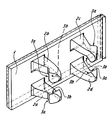
- the drawing shows a label in perspective and bottom view according to the invention.
- the label has a label carrier plate 1, on with the label on the top. It is in the usual Way any type of labeling technique, including labeling on plotters.
- Locking elements on the underside of the label carrier plate 1 for locking in mutually parallel locking channels electrical / electronic Components.
- Locking elements of a label consisting of four individual locking legs 2a, 2b, 2c, 2d.
- Each of the four locking legs 2a - 2d has two around Locking contours 3a, 3b offset from one another by 90 ° for locking with corresponding locking contours of the locking channels of the electrical / electronic Components.
- the two are available for locking Locking channels of the different locking systems always a total of four locking contours 3a, 3b, which then interact in pairs with the locking channels Detent legs 2a - 2d available.
- the latch leg pairs 2a and 2b and 2c and 2d within these pair groups a smaller distance from each other as the locking legs in the pair combination 2a and 2d as well as 2b and 2c. This is due to the different distances parallel locking channels of the different locking systems.
- Locking channel system When such a label is snapped into one Locking channel system, for example the one with the smaller distance of the locking channels from each other, act in pairs with these locking channels the locking legs 2a and 2b with their inner, facing each other facing locking contours 3b and the pair of legs 2c and 2d together with the corresponding locking contours 3b.
- the locking legs 2a and 2d act in pairs with their insofar as the outside of the locking contours 3a and the locking leg pair 2b and 2c also with the corresponding external snap contours 3a together.
Landscapes
- Physics & Mathematics (AREA)
- General Physics & Mathematics (AREA)
- Engineering & Computer Science (AREA)
- Theoretical Computer Science (AREA)
- Burglar Alarm Systems (AREA)
- Details Of Rigid Or Semi-Rigid Containers (AREA)
- Lock And Its Accessories (AREA)
- Details Of Connecting Devices For Male And Female Coupling (AREA)
- Mounting Components In General For Electric Apparatus (AREA)
- Coupling Device And Connection With Printed Circuit (AREA)
Claims (4)
- Etiquette de repérage comportant une plaque de support de repérage et des éléments d'encliquetage, situés au-dessous, pour l'encliquetage dans des canaux d'encliquetage, parallèles entre eux, de composants électriques/électroniques, caractérisée en ce que les éléments d'encliquetage d'une étiquette de repérage sont constitués de quatre jambes d'encliquetage (2a, 2b, 2c, 2d) et chaque jambe d'encliquetage présente deux contours d'encliquetage (3a, 3b), décalés entre eux de 90°.
- Etiquette de repérage selon la revendication 1, caractérisée en ce que les jambes d'encliquetage (2a, 2b, 2c, 2d) sont disposées deux par deux et présentent deux par deux (2a et 2b, 2c et 2d ; 2a et 2d, 2b et 2c) des distances différentes, décalées entre elles de 90°.
- Etiquette de repérage selon l'une des revendications précédentes, caractérisée en ce que les paires de jambes d'encliquetage (2a et 2d ; 2b et 2c) disposées suivant un plus grand écartement l'une de l'autre, possèdent sur leur côté extérieur des contours d'encliquetage (3a) coopérants.
- Etiquette de repérage selon l'une des revendications précédentes, caractérisée en ce que les paires de jambes d'encliquetage (2a et 2b ; 2c et 2d), disposées suivant un plus petit écartement, possèdent leurs contours d'encliquetage (3b) coopérants sur des côtés intérieurs tournés l'un vers l'autre.
Applications Claiming Priority (2)
| Application Number | Priority Date | Filing Date | Title |
|---|---|---|---|
| DE9417391U | 1994-10-29 | ||
| DE9417391U DE9417391U1 (de) | 1994-10-29 | 1994-10-29 | Bezeichnungsschild zur Verrastung in elektrisch/elektronischen Bauelementen |
Publications (2)
| Publication Number | Publication Date |
|---|---|
| EP0709817A1 EP0709817A1 (fr) | 1996-05-01 |
| EP0709817B1 true EP0709817B1 (fr) | 1998-04-29 |
Family
ID=6915473
Family Applications (1)
| Application Number | Title | Priority Date | Filing Date |
|---|---|---|---|
| EP95113743A Expired - Lifetime EP0709817B1 (fr) | 1994-10-29 | 1995-09-01 | Panneau de marquage destiné à être fixé sur un élément de construction électrique ou électronique |
Country Status (3)
| Country | Link |
|---|---|
| EP (1) | EP0709817B1 (fr) |
| AT (1) | ATE165688T1 (fr) |
| DE (2) | DE9417391U1 (fr) |
Cited By (1)
| Publication number | Priority date | Publication date | Assignee | Title |
|---|---|---|---|---|
| DE202004010070U1 (de) * | 2004-06-25 | 2005-11-10 | Weidmüller Interface GmbH & Co. KG | Bezeichnungsschild |
Families Citing this family (3)
| Publication number | Priority date | Publication date | Assignee | Title |
|---|---|---|---|---|
| DE102006003780A1 (de) * | 2005-09-01 | 2007-03-08 | Murrplastik Systemtechnik Gmbh | Kennzeichnungsschildersatz |
| DE202008009018U1 (de) | 2008-07-07 | 2009-11-12 | Phoenix Contact Gmbh & Co. Kg | Bezeichnungsschild mit Bezeichnungsträgerplatte für elektrische und elektronische Bauelemente |
| DE102019105520A1 (de) * | 2019-03-05 | 2020-09-10 | Phoenix Contact Gmbh & Co. Kg | Beschriftungsprofil zur Kennzeichnung von Elektroinstallationen und Verfahren zum Herstellen eines Beschriftungsprofils |
Family Cites Families (3)
| Publication number | Priority date | Publication date | Assignee | Title |
|---|---|---|---|---|
| ZA82400B (en) * | 1982-01-21 | 1982-12-29 | Mimic Displays | Support structures |
| FR2629527B1 (fr) * | 1988-04-01 | 1990-06-08 | Loire Electronique | Dispositif de fixation de plaquettes sur une cloison, en particulier de plaquettes-logos ou de marques sur un coffret ou une carrosserie |
| DE3932066C1 (en) * | 1989-09-26 | 1990-11-29 | Phoenix Elektrizitaetsgesellschaft H. Knuemann Gmbh & Co Kg, 4933 Blomberg, De | Clamping identification tabs for leads - can be retro-fitted by clamping jaws on rear of recessed label carrier |
-
1994
- 1994-10-29 DE DE9417391U patent/DE9417391U1/de not_active Expired - Lifetime
-
1995
- 1995-09-01 DE DE59502044T patent/DE59502044D1/de not_active Expired - Lifetime
- 1995-09-01 AT AT95113743T patent/ATE165688T1/de not_active IP Right Cessation
- 1995-09-01 EP EP95113743A patent/EP0709817B1/fr not_active Expired - Lifetime
Cited By (1)
| Publication number | Priority date | Publication date | Assignee | Title |
|---|---|---|---|---|
| DE202004010070U1 (de) * | 2004-06-25 | 2005-11-10 | Weidmüller Interface GmbH & Co. KG | Bezeichnungsschild |
Also Published As
| Publication number | Publication date |
|---|---|
| ATE165688T1 (de) | 1998-05-15 |
| DE59502044D1 (de) | 1998-06-04 |
| EP0709817A1 (fr) | 1996-05-01 |
| DE9417391U1 (de) | 1994-12-08 |
Similar Documents
| Publication | Publication Date | Title |
|---|---|---|
| EP0552413B1 (fr) | Marqueur pour des barrettes à bornes | |
| DE29606759U1 (de) | Mehrteiliges Gehäuse in Modulbauweise zur Aufnahme einer Leiterplatte | |
| DE59303280C5 (de) | Vorrichtung mit einem kunststoffträger zur aufnahme und halterung eines elektronischen moduls | |
| EP0709817B1 (fr) | Panneau de marquage destiné à être fixé sur un élément de construction électrique ou électronique | |
| DE2807061B2 (de) | Aus Einzeltasten zusammensetzbare Tastatur | |
| DE3687508T2 (de) | Zusatzgeraet wie z.b. ein funktionsstreifen. | |
| EP0929135A2 (fr) | Adaptateur multifonction pour des barres d'un système de barres omnibus | |
| EP0307787B1 (fr) | Boîtier pour lecteur de carte à circuit intégré | |
| DE3324652C1 (de) | Reihenklemmenblock | |
| EP2490237A1 (fr) | Panneau à affichage modifiable pour appareils encastrables en série | |
| DE10052025A1 (de) | Kartenlesevorrichtung für SIM-Karten | |
| DE2116342A1 (de) | Elektrische Steckverbinder | |
| DE3507694C1 (de) | Vorrichtung zum Kennzeichnen von Anschlüssen, Anschlußleitungen u.dgl. an elektrischen Geräten, Bauteilen u.dgl. | |
| DE202014106230U1 (de) | Elektrischer Steckverbinder und Steckverbinderanordnung | |
| DE8911016U1 (de) | Schlüssel mit einer Informationselektronik | |
| DE3928270C2 (fr) | ||
| DE3208991C2 (de) | Gehäuse für Leiterkarten | |
| DE19902811C1 (de) | Kodiervorrichtung und Kodierverfahren zur Kodierung eines elektrischen Gerätes | |
| DE1980771U (de) | Steckbares fuehrungsstueck zur beliebigen unterteilung von aufnahmevorrichtungen fuer elektrische plattenbaugruppen. | |
| DE29910179U1 (de) | Steckverbinder für elektrische Steuerungen | |
| DE1942960A1 (de) | Gehaeuse fuer einen zum Einbau in elektrische Nachrichtengeraete bestimmten Baustein,der einen Kleintransformator enthaelt | |
| DE7520329U (de) | Führungsleiste zum Führen und Halten von Schaltungsplatten | |
| DE7710127U1 (de) | Anschlußklemmvorrichtung, insbesondere für Stromkreisverteiler | |
| DE8413596U1 (de) | Kühlkörper für elektronische Bauelemente | |
| DE2616930A1 (de) | Elektrische doppel-reihenklemme |
Legal Events
| Date | Code | Title | Description |
|---|---|---|---|
| PUAI | Public reference made under article 153(3) epc to a published international application that has entered the european phase |
Free format text: ORIGINAL CODE: 0009012 |
|
| 17P | Request for examination filed |
Effective date: 19960229 |
|
| AK | Designated contracting states |
Kind code of ref document: A1 Designated state(s): AT CH DE FR GB IT LI SE |
|
| GRAG | Despatch of communication of intention to grant |
Free format text: ORIGINAL CODE: EPIDOS AGRA |
|
| 17Q | First examination report despatched |
Effective date: 19970901 |
|
| GRAG | Despatch of communication of intention to grant |
Free format text: ORIGINAL CODE: EPIDOS AGRA |
|
| GRAH | Despatch of communication of intention to grant a patent |
Free format text: ORIGINAL CODE: EPIDOS IGRA |
|
| ITF | It: translation for a ep patent filed | ||
| GRAH | Despatch of communication of intention to grant a patent |
Free format text: ORIGINAL CODE: EPIDOS IGRA |
|
| GRAA | (expected) grant |
Free format text: ORIGINAL CODE: 0009210 |
|
| AK | Designated contracting states |
Kind code of ref document: B1 Designated state(s): AT CH DE FR GB IT LI SE |
|
| REF | Corresponds to: |
Ref document number: 165688 Country of ref document: AT Date of ref document: 19980515 Kind code of ref document: T |
|
| REG | Reference to a national code |
Ref country code: CH Ref legal event code: EP |
|
| GBT | Gb: translation of ep patent filed (gb section 77(6)(a)/1977) |
Effective date: 19980430 |
|
| REF | Corresponds to: |
Ref document number: 59502044 Country of ref document: DE Date of ref document: 19980604 |
|
| ET | Fr: translation filed | ||
| PLBE | No opposition filed within time limit |
Free format text: ORIGINAL CODE: 0009261 |
|
| STAA | Information on the status of an ep patent application or granted ep patent |
Free format text: STATUS: NO OPPOSITION FILED WITHIN TIME LIMIT |
|
| 26N | No opposition filed | ||
| REG | Reference to a national code |
Ref country code: GB Ref legal event code: IF02 |
|
| REG | Reference to a national code |
Ref country code: CH Ref legal event code: PCAR Free format text: ISLER & PEDRAZZINI AG;POSTFACH 1772;8027 ZUERICH (CH) |
|
| PGFP | Annual fee paid to national office [announced via postgrant information from national office to epo] |
Ref country code: SE Payment date: 20090915 Year of fee payment: 15 Ref country code: GB Payment date: 20090922 Year of fee payment: 15 Ref country code: CH Payment date: 20090923 Year of fee payment: 15 Ref country code: AT Payment date: 20090916 Year of fee payment: 15 |
|
| PGFP | Annual fee paid to national office [announced via postgrant information from national office to epo] |
Ref country code: DE Payment date: 20090922 Year of fee payment: 15 |
|
| PGFP | Annual fee paid to national office [announced via postgrant information from national office to epo] |
Ref country code: IT Payment date: 20090926 Year of fee payment: 15 |
|
| REG | Reference to a national code |
Ref country code: CH Ref legal event code: PL |
|
| REG | Reference to a national code |
Ref country code: SE Ref legal event code: EUG |
|
| GBPC | Gb: european patent ceased through non-payment of renewal fee |
Effective date: 20100901 |
|
| PG25 | Lapsed in a contracting state [announced via postgrant information from national office to epo] |
Ref country code: IT Free format text: LAPSE BECAUSE OF NON-PAYMENT OF DUE FEES Effective date: 20100901 |
|
| REG | Reference to a national code |
Ref country code: FR Ref legal event code: ST Effective date: 20110531 |
|
| REG | Reference to a national code |
Ref country code: DE Ref legal event code: R119 Ref document number: 59502044 Country of ref document: DE Effective date: 20110401 |
|
| PG25 | Lapsed in a contracting state [announced via postgrant information from national office to epo] |
Ref country code: LI Free format text: LAPSE BECAUSE OF NON-PAYMENT OF DUE FEES Effective date: 20100930 Ref country code: FR Free format text: LAPSE BECAUSE OF NON-PAYMENT OF DUE FEES Effective date: 20100930 Ref country code: CH Free format text: LAPSE BECAUSE OF NON-PAYMENT OF DUE FEES Effective date: 20100930 Ref country code: DE Free format text: LAPSE BECAUSE OF NON-PAYMENT OF DUE FEES Effective date: 20110401 |
|
| PG25 | Lapsed in a contracting state [announced via postgrant information from national office to epo] |
Ref country code: GB Free format text: LAPSE BECAUSE OF NON-PAYMENT OF DUE FEES Effective date: 20100901 Ref country code: AT Free format text: LAPSE BECAUSE OF NON-PAYMENT OF DUE FEES Effective date: 20100901 |
|
| PGFP | Annual fee paid to national office [announced via postgrant information from national office to epo] |
Ref country code: FR Payment date: 20091001 Year of fee payment: 15 |
|
| PG25 | Lapsed in a contracting state [announced via postgrant information from national office to epo] |
Ref country code: SE Free format text: LAPSE BECAUSE OF NON-PAYMENT OF DUE FEES Effective date: 20100902 |