EP0709854A1 - Gerät zur Überwachung des Neutronenflusses in der Spaltzone eines Kernreaktors - Google Patents
Gerät zur Überwachung des Neutronenflusses in der Spaltzone eines Kernreaktors Download PDFInfo
- Publication number
- EP0709854A1 EP0709854A1 EP94830499A EP94830499A EP0709854A1 EP 0709854 A1 EP0709854 A1 EP 0709854A1 EP 94830499 A EP94830499 A EP 94830499A EP 94830499 A EP94830499 A EP 94830499A EP 0709854 A1 EP0709854 A1 EP 0709854A1
- Authority
- EP
- European Patent Office
- Prior art keywords
- nuclear
- solid
- detector elements
- state
- core
- Prior art date
- Legal status (The legal status is an assumption and is not a legal conclusion. Google has not performed a legal analysis and makes no representation as to the accuracy of the status listed.)
- Withdrawn
Links
- 230000004907 flux Effects 0.000 title claims abstract description 18
- 238000012544 monitoring process Methods 0.000 title claims abstract description 10
- 230000005855 radiation Effects 0.000 claims description 7
- 239000000463 material Substances 0.000 claims description 5
- LBDSXVIYZYSRII-IGMARMGPSA-N alpha-particle Chemical compound [4He+2] LBDSXVIYZYSRII-IGMARMGPSA-N 0.000 claims description 3
- 230000003993 interaction Effects 0.000 claims description 3
- 229910052793 cadmium Inorganic materials 0.000 claims description 2
- BDOSMKKIYDKNTQ-UHFFFAOYSA-N cadmium atom Chemical compound [Cd] BDOSMKKIYDKNTQ-UHFFFAOYSA-N 0.000 claims description 2
- 230000008901 benefit Effects 0.000 description 6
- 235000012431 wafers Nutrition 0.000 description 6
- 239000000446 fuel Substances 0.000 description 4
- 230000015572 biosynthetic process Effects 0.000 description 3
- 238000006243 chemical reaction Methods 0.000 description 3
- 238000009835 boiling Methods 0.000 description 2
- 238000001816 cooling Methods 0.000 description 2
- 230000000694 effects Effects 0.000 description 2
- 230000004992 fission Effects 0.000 description 2
- 238000000034 method Methods 0.000 description 2
- 230000000149 penetrating effect Effects 0.000 description 2
- 230000009466 transformation Effects 0.000 description 2
- XLYOFNOQVPJJNP-UHFFFAOYSA-N water Substances O XLYOFNOQVPJJNP-UHFFFAOYSA-N 0.000 description 2
- 230000002159 abnormal effect Effects 0.000 description 1
- 230000009471 action Effects 0.000 description 1
- 230000002411 adverse Effects 0.000 description 1
- 238000013459 approach Methods 0.000 description 1
- 230000015556 catabolic process Effects 0.000 description 1
- 238000005253 cladding Methods 0.000 description 1
- 239000004020 conductor Substances 0.000 description 1
- 239000002826 coolant Substances 0.000 description 1
- 238000013506 data mapping Methods 0.000 description 1
- 230000001627 detrimental effect Effects 0.000 description 1
- 239000006185 dispersion Substances 0.000 description 1
- 230000006872 improvement Effects 0.000 description 1
- 150000002500 ions Chemical class 0.000 description 1
- 238000013178 mathematical model Methods 0.000 description 1
- 238000005259 measurement Methods 0.000 description 1
- 230000007246 mechanism Effects 0.000 description 1
- 230000005012 migration Effects 0.000 description 1
- 238000013508 migration Methods 0.000 description 1
- 238000012986 modification Methods 0.000 description 1
- 230000004048 modification Effects 0.000 description 1
- 238000013021 overheating Methods 0.000 description 1
- 239000002245 particle Substances 0.000 description 1
- 239000008188 pellet Substances 0.000 description 1
- 230000008569 process Effects 0.000 description 1
- 238000012545 processing Methods 0.000 description 1
- 238000007670 refining Methods 0.000 description 1
- 239000004065 semiconductor Substances 0.000 description 1
- 229910052710 silicon Inorganic materials 0.000 description 1
- 239000010703 silicon Substances 0.000 description 1
Images
Classifications
-
- G—PHYSICS
- G21—NUCLEAR PHYSICS; NUCLEAR ENGINEERING
- G21C—NUCLEAR REACTORS
- G21C17/00—Monitoring; Testing ; Maintaining
- G21C17/10—Structural combination of fuel element, control rod, reactor core, or moderator structure with sensitive instruments, e.g. for measuring radioactivity, strain
- G21C17/108—Measuring reactor flux
-
- Y—GENERAL TAGGING OF NEW TECHNOLOGICAL DEVELOPMENTS; GENERAL TAGGING OF CROSS-SECTIONAL TECHNOLOGIES SPANNING OVER SEVERAL SECTIONS OF THE IPC; TECHNICAL SUBJECTS COVERED BY FORMER USPC CROSS-REFERENCE ART COLLECTIONS [XRACs] AND DIGESTS
- Y02—TECHNOLOGIES OR APPLICATIONS FOR MITIGATION OR ADAPTATION AGAINST CLIMATE CHANGE
- Y02E—REDUCTION OF GREENHOUSE GAS [GHG] EMISSIONS, RELATED TO ENERGY GENERATION, TRANSMISSION OR DISTRIBUTION
- Y02E30/00—Energy generation of nuclear origin
- Y02E30/30—Nuclear fission reactors
Definitions
- the present invention relates to apparatus for monitoring the neutron flux generated in the core of a nuclear reactor. More particularly, the core is enclosed in a pressure vessel which delimits the nuclear reactor and which is substantially cylindrical in shape with an axis of symmetry.
- known types of apparatus for monitoring neutron flux include a plurality of elements for detecting nuclear emissions arranged outside the pressure vessel to detect the nuclear emissions from the vessel which are the result of the neutron flux associated with the nuclear fission reactions which produce the energy in the core.
- the nuclear emission detector elements used in the prior art are ionisation chambers.
- Such chambers comprise a receptacle containing gas subjected to a suitable potential difference by two or more electrodes.
- the incident nuclear emissions ionise the atoms of the gas in the chamber and the ions are collected by the respective electrodes and cause a current to flow which can be detected by a galvanometer.
- the magnitude of the current generated depends on the type and intensity of the incident nuclear emissions.
- the ionisation chambers described above are located outside the pressure vessel in a zone corresponding to the position of the fuel in the core, which is substantially cylindrical and coaxial with the vessel.
- More advanced versions of the monitoring apparatus include six ionisation chambers located on lines parallel to the axis of symmetry of the pressure vessel in each of its quadrants, there being a total of twenty four ionisation chambers.
- the purpose of this apparatus is to determine, as precisely as possible, both the instantaneous power generated and the difference between the power generated at the upper and lower ends of the core.
- This difference if it exists, is caused, for example, by temperature gradients in the coolant in the cooling ducts in the core which differ from those envisaged during normal operation or, in the case of water-cooled nuclear reactors, by an abnormal distribution of the vacant portions of the ducts.
- Ionisation chambers provide an overall measure of the nuclear emissions in the volume of the chambers traversed by the said emissions from the core and the data obtained are processed with the aid of Fourier series. It will readily be understood that an increase in the number of ionisation chambers beyond six would not bring significant increases in precision in the information required.
- ionisation chambers are generally bulky as well as very expensive and difficult to maintain and, hence, an increase in their number would have a significantly adverse effect on the building in which the pressure vessel is housed and also on the surface of the vessel itself.
- the main effect of this would be detrimental to the safety of the nuclear reactor in general in that the lack of space around the pressure vessel might limit the speed and efficiency of any action required to restore safe operating conditions in the event of an incident.
- the technical problem which forms the basis of the present invention consists of making available apparatus for monitoring the neutron flux which overcomes the disadvantages mentioned above with reference to the prior art while simultaneously satisfying the said requirement.
- apparatus of the type specified characterised in that it includes a plurality of solid-state elements for detecting nuclear emissions arranged outside the pressure vessel.
- the main advantage of the apparatus of the invention lies in the fact that solid-state nuclear-emission detectors are small, cheap and easy to use so that it is possible to use a large quantity to obtain data mapping from a large number of points.
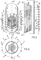
- a nuclear reactor is schematically indicated 1. It is defined and delimited by a pressure vessel 2 of cylindrical shape with a vertical axis of symmetry A.
- apparatus 10 for monitoring the neutron flux generated by the core 3 of the nuclear reactor 1. It includes a plurality of solid-state nuclear-emission detector elements 4 which are arranged on a substantially cylindrical surface 5 concentric with the vessel 2.
- the apparatus 10 will thus have the same number of lines 7 as the number of nuclear-emission detector elements 4 on each circle 6.
- the circles 6 are suitably spaced from each other and suitably located relative to the core 3 of the nuclear reactor 1 ( Figures 1 and 2).
- the core 3 is the seat of nuclear fission reactions responsible for the generation of thermal energy, one product of the reactions being a neutron flux with which an emission of nuclear radiation is associated. More particularly, the gamma radiation, in this case conventionally termed n-gamma, is the most easy to measure as it is particularly penetrating and thus not subject to dispersion or attenuation.
- Solid-state nuclear-emission detector elements consist of pellets, conventionally termed wafers, of semi-conductive material, for example silicon, with opposite surfaces metallised to serve as electrodes. These wafers, when exposed to the nuclear emissions to be measured, are polarised electrically by the application of a predetermined potential difference to the electrodes. Without entering into detail about the mechanisms for the formation and migration of electric charges in semi-conductive wafers, these emissions cause a variation in the electrical conductivity of the wafer which results in a measurable signal constituted by the magnitude of the current through the wafer.
- the apparatus 10 includes a plurality of nuclear-emission detector elements 4 from which there is derived a uniform map of data relating to individual points on the surface 5. In fact the dimensions of the semi-conductor wafer are negligible compared with those of the core 3.
- the preferred version of the apparatus 10 which is the subject of the present description includes at least twenty circles 6 on each of which there are at least eight detector elements 4 so that there are eight lines 7 each including twenty detector elements 4.
- the detector elements 4 are arranged to monitor gamma radiation.
- each detector element 4 is arranged in a casing 4a of a material in which n-alpha-type interactions occur ( Figure 3).
- This material when bombarded by a neutron flux, emits a corresponding flow of alpha particles which, as known, have little penetrating power and must therefore be detected close to the point of emission.
- the material includes cadmium.
- the neutron flux emitted by the core 3 of the nuclear reactor 1 is not itself detectable by the solid-state detector elements but is monitored indirectly via the intensity of the alpha-particle emissions to which the neutron flux is linked through a known transformation function.
- detector elements 4 which can measure alpha-particle emissions.
- a further advantage of the apparatus 10 of the invention lies in the fact that the nuclear-emission detector elements 4 are easy to control, calibrate and replace in the case of breakdown.
Landscapes
- Physics & Mathematics (AREA)
- Engineering & Computer Science (AREA)
- Plasma & Fusion (AREA)
- General Engineering & Computer Science (AREA)
- High Energy & Nuclear Physics (AREA)
- Monitoring And Testing Of Nuclear Reactors (AREA)
Priority Applications (1)
| Application Number | Priority Date | Filing Date | Title |
|---|---|---|---|
| EP94830499A EP0709854A1 (de) | 1994-10-26 | 1994-10-26 | Gerät zur Überwachung des Neutronenflusses in der Spaltzone eines Kernreaktors |
Applications Claiming Priority (1)
| Application Number | Priority Date | Filing Date | Title |
|---|---|---|---|
| EP94830499A EP0709854A1 (de) | 1994-10-26 | 1994-10-26 | Gerät zur Überwachung des Neutronenflusses in der Spaltzone eines Kernreaktors |
Publications (1)
| Publication Number | Publication Date |
|---|---|
| EP0709854A1 true EP0709854A1 (de) | 1996-05-01 |
Family
ID=8218554
Family Applications (1)
| Application Number | Title | Priority Date | Filing Date |
|---|---|---|---|
| EP94830499A Withdrawn EP0709854A1 (de) | 1994-10-26 | 1994-10-26 | Gerät zur Überwachung des Neutronenflusses in der Spaltzone eines Kernreaktors |
Country Status (1)
| Country | Link |
|---|---|
| EP (1) | EP0709854A1 (de) |
Cited By (3)
| Publication number | Priority date | Publication date | Assignee | Title |
|---|---|---|---|---|
| US8153985B2 (en) | 2009-01-30 | 2012-04-10 | Honeywell International Inc. | Neutron detector cell efficiency |
| US8310021B2 (en) | 2010-07-13 | 2012-11-13 | Honeywell International Inc. | Neutron detector with wafer-to-wafer bonding |
| JP2019109076A (ja) * | 2017-12-15 | 2019-07-04 | 株式会社東芝 | 炉内状況測定装置および炉内状況測定方法 |
Citations (3)
| Publication number | Priority date | Publication date | Assignee | Title |
|---|---|---|---|---|
| GB1023117A (en) * | 1963-07-29 | 1966-03-16 | Ca Atomic Energy Ltd | Improvements in neutron flux detectors |
| US3603793A (en) * | 1969-08-01 | 1971-09-07 | Babcock & Wilcox Co | Radiation detector solid state radiation detection using an insulator between the emitter and collector |
| FR2343313A1 (fr) * | 1976-03-05 | 1977-09-30 | Westinghouse Electric Corp | Procede et appareil de controle de la repartition de puissance dans le coeur d'un reacteur nucleaire |
-
1994
- 1994-10-26 EP EP94830499A patent/EP0709854A1/de not_active Withdrawn
Patent Citations (3)
| Publication number | Priority date | Publication date | Assignee | Title |
|---|---|---|---|---|
| GB1023117A (en) * | 1963-07-29 | 1966-03-16 | Ca Atomic Energy Ltd | Improvements in neutron flux detectors |
| US3603793A (en) * | 1969-08-01 | 1971-09-07 | Babcock & Wilcox Co | Radiation detector solid state radiation detection using an insulator between the emitter and collector |
| FR2343313A1 (fr) * | 1976-03-05 | 1977-09-30 | Westinghouse Electric Corp | Procede et appareil de controle de la repartition de puissance dans le coeur d'un reacteur nucleaire |
Cited By (4)
| Publication number | Priority date | Publication date | Assignee | Title |
|---|---|---|---|---|
| US8153985B2 (en) | 2009-01-30 | 2012-04-10 | Honeywell International Inc. | Neutron detector cell efficiency |
| US8399845B2 (en) | 2009-01-30 | 2013-03-19 | Honeywell International Inc. | Neutron detector cell efficiency |
| US8310021B2 (en) | 2010-07-13 | 2012-11-13 | Honeywell International Inc. | Neutron detector with wafer-to-wafer bonding |
| JP2019109076A (ja) * | 2017-12-15 | 2019-07-04 | 株式会社東芝 | 炉内状況測定装置および炉内状況測定方法 |
Similar Documents
| Publication | Publication Date | Title |
|---|---|---|
| US4637910A (en) | Method and apparatus for continuous on-line synthesis of power distribution in a nuclear reactor core | |
| CA1079419A (en) | Method and apparatus for monitoring the axial power distribution within the core of a nuclear reactor, exterior of the reactor | |
| EP3036745B1 (de) | Ionisationskammerstrahlungsdetektor | |
| EP3374996B1 (de) | Subkritischer reaktivitätsmonitor mit unverzüglichen selbstangetriebenen incore-detektoren | |
| EP2661644B1 (de) | Selbstangetriebener drahtloser in-core-detektor | |
| EP3170185B1 (de) | Thermoakustische messanordnung für atomkraftverteilung | |
| EP0138542B1 (de) | Verfahren und Anordnung zum Feststellen der Kritikalitätsnähe eines Kernreaktors | |
| EP0241301A2 (de) | Axiales Leistungsverteilungsüberwachungsgerät und Anzeige mit Verarbeitung von Ausgangsdaten aus Detektoren und Thermopaaren ausserhalb der Spaltzone | |
| JP3064084B2 (ja) | 原子炉用の出力振動範囲を監視する装置と方法 | |
| WO2013095735A1 (en) | Pool level indication system | |
| JP2000147187A (ja) | 中性子束計測装置 | |
| US20140321591A1 (en) | Thermo-acoustic nuclear power distribution measurement assembly | |
| US4708844A (en) | Reactor monitoring assembly | |
| EP0490162B1 (de) | Verfahren und Detektor zur Messung des Unterkanalleeranteils in einem Leichtwasserkernreaktor-Testbrennstabbündel | |
| US4649015A (en) | Monitoring system for a liquid-cooled nuclear fission reactor | |
| JPS6337358B2 (de) | ||
| RU2068205C1 (ru) | Способ оперативного контроля состояния топлива в тепловыделяющей сборке ядерного реактора | |
| EP0258958B1 (de) | Auffinden eines gebrochenen Brennstabbündels in einem in Betrieb befindlichen Kernreaktor | |
| US3393126A (en) | Testing for fuel element sheathing failures in nuclear reactors | |
| Dawson et al. | Instrumentation at Berkeley nuclear power station | |
| Dastidar | Electronics in nuclear science and technology | |
| Buksha et al. | An analysis of used and under-development methods of fast-reactor core subassemblies monitoring in the USSR | |
| JPH06235771A (ja) | 多素子型中性子検出装置 | |
| Bell et al. | RADCAL-based reactor vessel monitoring system for inadequate core cooling determination | |
| Neef et al. | Detection of flux perturbations in pebble bed HTGRs by near core instrumentation |
Legal Events
| Date | Code | Title | Description |
|---|---|---|---|
| PUAI | Public reference made under article 153(3) epc to a published international application that has entered the european phase |
Free format text: ORIGINAL CODE: 0009012 |
|
| AK | Designated contracting states |
Kind code of ref document: A1 Designated state(s): DE ES FR GB IT |
|
| 17P | Request for examination filed |
Effective date: 19960613 |
|
| 17Q | First examination report despatched |
Effective date: 19970109 |
|
| STAA | Information on the status of an ep patent application or granted ep patent |
Free format text: STATUS: THE APPLICATION IS DEEMED TO BE WITHDRAWN |
|
| 18D | Application deemed to be withdrawn |
Effective date: 19971119 |