EP0709857A1 - Enveloppe d'assemblage du combustible nucléaire ayante des moyens de centrage pour grille d'espacement - Google Patents
Enveloppe d'assemblage du combustible nucléaire ayante des moyens de centrage pour grille d'espacement Download PDFInfo
- Publication number
- EP0709857A1 EP0709857A1 EP95307320A EP95307320A EP0709857A1 EP 0709857 A1 EP0709857 A1 EP 0709857A1 EP 95307320 A EP95307320 A EP 95307320A EP 95307320 A EP95307320 A EP 95307320A EP 0709857 A1 EP0709857 A1 EP 0709857A1
- Authority
- EP
- European Patent Office
- Prior art keywords
- channel
- spacers
- fuel assembly
- fuel
- locations
- Prior art date
- Legal status (The legal status is an assumption and is not a legal conclusion. Google has not performed a legal analysis and makes no representation as to the accuracy of the status listed.)
- Withdrawn
Links
- 239000000446 fuel Substances 0.000 title claims abstract description 82
- 125000006850 spacer group Chemical group 0.000 title claims abstract description 79
- 239000002826 coolant Substances 0.000 claims abstract description 12
- 230000006872 improvement Effects 0.000 claims abstract description 5
- 238000007373 indentation Methods 0.000 description 21
- 230000002093 peripheral effect Effects 0.000 description 10
- 238000013461 design Methods 0.000 description 8
- XLYOFNOQVPJJNP-UHFFFAOYSA-N water Substances O XLYOFNOQVPJJNP-UHFFFAOYSA-N 0.000 description 8
- 238000009835 boiling Methods 0.000 description 5
- 239000000463 material Substances 0.000 description 4
- 239000007787 solid Substances 0.000 description 3
- 239000007788 liquid Substances 0.000 description 2
- 239000011159 matrix material Substances 0.000 description 2
- 238000012986 modification Methods 0.000 description 2
- 230000004048 modification Effects 0.000 description 2
- 239000002574 poison Substances 0.000 description 2
- 231100000614 poison Toxicity 0.000 description 2
- VAYOSLLFUXYJDT-RDTXWAMCSA-N Lysergic acid diethylamide Chemical class C1=CC(C=2[C@H](N(C)C[C@@H](C=2)C(=O)N(CC)CC)C2)=C3C2=CNC3=C1 VAYOSLLFUXYJDT-RDTXWAMCSA-N 0.000 description 1
- 238000005760 Tripper reaction Methods 0.000 description 1
- 238000010276 construction Methods 0.000 description 1
- 230000009977 dual effect Effects 0.000 description 1
- 238000009434 installation Methods 0.000 description 1
- 238000012423 maintenance Methods 0.000 description 1
- 238000004519 manufacturing process Methods 0.000 description 1
- 239000002184 metal Substances 0.000 description 1
- 238000000034 method Methods 0.000 description 1
- 230000009467 reduction Effects 0.000 description 1
- 238000012360 testing method Methods 0.000 description 1
- 230000007704 transition Effects 0.000 description 1
Images

Classifications
-
- G—PHYSICS
- G21—NUCLEAR PHYSICS; NUCLEAR ENGINEERING
- G21C—NUCLEAR REACTORS
- G21C3/00—Reactor fuel elements and their assemblies; Selection of substances for use as reactor fuel elements
- G21C3/30—Assemblies of a number of fuel elements in the form of a rigid unit
- G21C3/32—Bundles of parallel pin-, rod-, or tube-shaped fuel elements
- G21C3/33—Supporting or hanging of elements in the bundle; Means forming part of the bundle for inserting it into, or removing it from, the core; Means for coupling adjacent bundles
- G21C3/332—Supports for spacer grids
-
- G—PHYSICS
- G21—NUCLEAR PHYSICS; NUCLEAR ENGINEERING
- G21C—NUCLEAR REACTORS
- G21C3/00—Reactor fuel elements and their assemblies; Selection of substances for use as reactor fuel elements
- G21C3/30—Assemblies of a number of fuel elements in the form of a rigid unit
- G21C3/32—Bundles of parallel pin-, rod-, or tube-shaped fuel elements
- G21C3/322—Means to influence the coolant flow through or around the bundles
-
- G—PHYSICS
- G21—NUCLEAR PHYSICS; NUCLEAR ENGINEERING
- G21C—NUCLEAR REACTORS
- G21C3/00—Reactor fuel elements and their assemblies; Selection of substances for use as reactor fuel elements
- G21C3/30—Assemblies of a number of fuel elements in the form of a rigid unit
- G21C3/32—Bundles of parallel pin-, rod-, or tube-shaped fuel elements
- G21C3/324—Coats or envelopes for the bundles
-
- Y—GENERAL TAGGING OF NEW TECHNOLOGICAL DEVELOPMENTS; GENERAL TAGGING OF CROSS-SECTIONAL TECHNOLOGIES SPANNING OVER SEVERAL SECTIONS OF THE IPC; TECHNICAL SUBJECTS COVERED BY FORMER USPC CROSS-REFERENCE ART COLLECTIONS [XRACs] AND DIGESTS
- Y02—TECHNOLOGIES OR APPLICATIONS FOR MITIGATION OR ADAPTATION AGAINST CLIMATE CHANGE
- Y02E—REDUCTION OF GREENHOUSE GAS [GHG] EMISSIONS, RELATED TO ENERGY GENERATION, TRANSMISSION OR DISTRIBUTION
- Y02E30/00—Energy generation of nuclear origin
- Y02E30/30—Nuclear fission reactors
Definitions
- This invention relates to fuel bundles in boiling water nuclear reactors. More specifically, the invention relates to improved designs for the channel and spacer components of the fuel bundle in the upper two-phase region of the bundle, which optimizes critical power performance.
- Fuel bundles in boiling water nuclear reactors include an array of upstanding side-by-side fuel rods supported between upper and lower tie plates. Each bundle requires multiple spacers (e.g., seven, axially spaced along the bundle) for the maintenance of the fuel rods in designed spaced apart relationship.
- the bundle is surrounded between the tie plates by a fuel bundle channel, which is hollow, elongated sleeve-like member of generally square cross-sectional shape.
- the lower tie plate is configured to permit the inflow of moderating water coolant through the channel while the upper tie plate permits the outflow of both water coolant and generated steam from the channel.
- the surrounding channel thus confines the flow of coolant to a path around the steam generating fuel rods separate from a water flooded core bypass region surrounding each fuel bundle.
- a conventional fuel assembly comprises a plurality of fuel elements or rods supported between an upper tie plate and a lower tie plate.
- the fuel rods pass through a plurality of fuel rod spacers which provide intermediate support and retain the elongated rods in spaced relation.
- Each spacer contains a matrix of ferrules F, each adapted to receive and surround a corresponding fuel rod. In a typical arrangement, seven such spacers may be located along the approximate foot length of the fuel bundle.
- Each of the fuel rods includes an elongated tube containing fissile fuel and other materials, such as fertile fuel, burnable poison, inert material or the like, sealed in the tube by upper and lower end plugs, respectively.
- Lower end plugs are formed with extensions for registration and support within openings formed in the lower tie plate.
- the upper end plugs are formed with extensions which fit into support openings in the upper tie plate.
- the fuel assembly also includes a thin walled tubular flow channel of substantially square cross section, sized to form a sliding fit over the upper and lower tie plates as well as spacers so that the channel may be easily mounted to or removed from the fuel bundle.
- a thin walled tubular flow channel of substantially square cross section, sized to form a sliding fit over the upper and lower tie plates as well as spacers so that the channel may be easily mounted to or removed from the fuel bundle.
- projecting lobes have been formed at spaced locations about the peripheral bands of the spacers for the purpose of centering the bundle within the channel, with predetermined clearance between the spacer lobes and channel (one such arrangement is shown in Figure 1, discussed below).
- the lower tie plate is formed with a nosepiece adapted to support the fuel assembly in a socket in a core support plate (not shown) in the reactor pressure vessel.
- the end of this nosepiece is formed with an opening which receives pressurized coolant in an upward flow direction.
- Critical power capability is one of the more important performance parameters for a BWR fuel bundle.
- Conventional BWR fuel bundles are placed in the surrounding channels with appropriate clearance (about 025 inch total clearance) between the channel and the contact points or lobes of the bundle spacers to allow the channel to slide over the bundle during final bundle assembly. Thereafter, however, it is impossible to know the exact position of the bundle relative to the channel walls which necessitates making conservative assumptions about corner rod-to-channel spacing, thus, losing considerable critical power performance potential.
- outer rod critical power performance may be as much as 5 to 10% higher when the bundle is centered within the channel rather than in its maximum offset position.
- the upper two-phase region of the fuel bundle channel is formed with peripheral indentations at axially spaced locations corresponding to the locations of the upper second and third fuel bundle spacers, i.e., the second and third spacers from the top of the bundle.
- the channel may be modified at locations corresponding to the first and/or fourth spacers as well.
- the cross sectional area of the channel walls at the precise axial locations of the upper spacers is reduced about the four sides of the channel.
- the spacers in these reduced area regions must also be modified so that they may fit within the indentations in the channel walls.
- the remaining spacers in the bundle may be of conventional design.
- the reduced size spacers can be centered within the indented areas by utilizing solid stops between the spacers and the indentations on two adjacent sides of the channel, and leaf spring members on the remaining adjacent two sides, again between the indentations and the spacer.
- the reduced size spacers can be centered within the indented areas of the channel utilizing fasteners inserted from the outside and through the channel walls. Other suitable attachment techniques are also within the scope of this invention.
- the present invention relates to a fuel assembly comprising a plurality of fuel rods positioned in a spaced array by upper and lower tie-plates, a plurality of axially spacers for maintaining the plurality of fuel rods in the spaced array; an open ended flow channel surrounding the array for conducting coolant upward about the fuel rods, the open ended channel having a polygon shaped cross section with substantially flat side sections connected between the corner sections; an improvement in the flow channel comprising a plurality of interior projections at each of a plurality of axially spaced locations in an upper portion only of the channel, the locations corresponding to placement of fuel rod spacers within the upper portion of the channel.
- the invention in another aspect, relates to a fuel assembly comprising a plurality of fuel rods positioned in a spaced array between upper and lower tie-plates; a plurality of axially spaced spacers for maintaining the plurality of fuel rods in the spaced array; an open ended flow channel surrounding the array for conducting coolant upward about the fuel rods, the open ended channel having a polygon shaped cross section with substantially flat side sections connected between the corner sections; the improvement comprising means for redirecting coolant on interior surfaces of the channel toward outer fuel rods in the array and simultaneously centering at least a pair of the spacers within the channel.
- a conventional fuel assembly 10 for a boiling water reactor comprises a plurality of fuel elements or rods 12 supported between an upper tie plate 14 and a lower tie plate 16.
- the fuel rods 12 pass through a plurality of fuel rod spacers 18 which provide intermediate support and retain the elongated rods in spaced relation.
- Each spacer contains a matrix of ferrules F, each adapted to receive and surround a corresponding fuel rod 12. In a typical arrangement, seven such spacers 18 may be located along the approximate 13 foot length of the fuel bundle.
- Each of the fuel rods 12 includes an elongated tube containing fissile fuel and other materials, such as fertile fuel, burnable poison, inert material or the like, sealed in the tube by upper and lower end plugs 20, 22, respectively.
- Lower end plugs 22 are formed with extensions for registration and support within openings formed in the lower tie plate 16.
- the upper end plugs 20 are formed with extensions which fit into support openings in the upper tie plate 14.
- the fuel assembly 10 also includes a thin walled tubular flow channel 24 of substantially square cross section, sized to form a sliding fit over the upper and lower tie plates 14 and 16 as well as spacers 18 so that the channel may be easily mounted to or removed from the fuel bundle.
- the peripheral bands of spacers 18 may be provided with projecting lobes or stops L which are intended to generally center the fuel bundle within the channel 24. It should be noted however, that there remains a specified clearance between the spacer lobes L and the interior walls of the channel 24 on the order of about .012 inch on each side, or about .025 inch total clearance between any two opposite sides of the spacer and adjacent channel walls.
- the lower tie plate 16 is formed with a nosepiece 26 adapted to support the fuel assembly 10 in a socket in a core support plate (not shown) in the reactor pressure vessel.
- the end of this nosepiece is formed with an opening 28 which receives pressurized coolant in an upward flow direction.
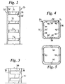
- a fuel bundle channel 30 in accordance with this invention is modified in the upper two-phase (steam and water) region to include four horizontally elongated recesses or indentations 32, 34, 36 and 38 about the periphery of the channel at each of three axially spaced locations corresponding to the three uppermost spacers S1, S2, S3 in the bundle.
- a fourth conventional spacer S4 is shown at an otherwise unmodified location along the channel.
- the recesses or indentations 32, 34, 36 and 38 form corresponding projections 32', 34', 36' and 38' within the interior of the channel 30 to thereby reduce the interior cross-sectional area of the channel at each such location.
- the channel 30 and the spacers S1 - S4 are shown in simplified form in Figures 2-5 to facilitate a clearer understanding of the invention.
- channel 30 and spacers S1 - S3 are shown as modified in accordance with this invention in Figure 2, the preferred arrangement is to modify the channel and respective spacers at only the S2 and S3 positions, with the application of this invention to the S1 and S4 locations optional, depending on design considerations. In any case, in a typical seven spacer arrangement, the channel and spacers at the locations of remaining spacers S5 - S7 (not shown) may be of conventional design.
- indentations shown at 32, 34, 36 and 38 are centered on respective sides of the channel 30.
- Each indentation is 20 to 40 mm in height and 25 to 50 mm in length in the preferred embodiment, and projects inwardly into the enclosed channel space forming the corresponding projections 32', 34', 36' and 38' which effectively decrease the cross-sectional area of the channel at the respective spacer locations S1, S2 and S3.
- Other dimensions and/or indentation shapes may be equally suitable.
- the channel itself may be provided with smooth interior wall surfaces and solid metal strips may be applied to the interior channel surfaces, thus serving the same function as the illustrated indentations 32, 34, 36 and 38. This is a less preferred arrangement, however, particularly in terms of manufacturing and related costs.
- Spacers S1, S2 and S3 necessarily are required to have a different band design from the conventional design spacers in the lower part of the bundle, in order to accommodate the reduced channel cross-sectional areas at these locations. More specifically, the upper spacers S1, S2 and S3 are designed with reduced perimeters so that they will be centered inside the indentations 32', 34', 36' and 38' in the channel wall at each of the corresponding spacer locations. Centering of each spacer within the indented channel area can be achieved in a variety of ways including essentially a near zero clearance between the indentations and the peripheral bands of the spacers.
- the spacer S1 for example (and as shown in Figure 4), can be centered within the area created by indentations 32, 34, 36 and 38 (and as also defined by interior channel projections 32', 34', 36' and 38') through the utilization of springs 40, 42 on adjacent spacer sides with solid stop pairs 44, 46 located on the remaining adjacent sides of the spacer peripheral band.
- Springs 40, 42 are preferably leaf springs mounted within the spacer peripheral band. It will be appreciated that a peripheral leaf spring (not shown) extending completely about the spacer peripheral band may also be utilized in place of the stops 44, 46 and springs 40, 42.
- each of the sides of the spacer peripheral band is secured to an adjacent channel wall indentation by a suitable fastener 50, which may be a simple nut and bolt arrangement as shown.
- a suitable fastener 50 which may be a simple nut and bolt arrangement as shown.
- the indentations 32, 34, 36, 38 and corresponding interior projections 32', 34', 36' and 38' in the channel side walls at each of the spacer locations S3 and S4 (and optionally at S1 and S2) serve a dual function.
- these indentations/projections maintain the spacers centered within the channel, thus avoiding critical power reduction due to uneven spacing.
Landscapes
- Physics & Mathematics (AREA)
- Engineering & Computer Science (AREA)
- Plasma & Fusion (AREA)
- General Engineering & Computer Science (AREA)
- High Energy & Nuclear Physics (AREA)
- Monitoring And Testing Of Nuclear Reactors (AREA)
- Details Of Heat-Exchange And Heat-Transfer (AREA)
Applications Claiming Priority (2)
| Application Number | Priority Date | Filing Date | Title |
|---|---|---|---|
| US328434 | 1981-12-07 | ||
| US32843494A | 1994-10-25 | 1994-10-25 |
Publications (1)
| Publication Number | Publication Date |
|---|---|
| EP0709857A1 true EP0709857A1 (fr) | 1996-05-01 |
Family
ID=23280967
Family Applications (1)
| Application Number | Title | Priority Date | Filing Date |
|---|---|---|---|
| EP95307320A Withdrawn EP0709857A1 (fr) | 1994-10-25 | 1995-10-16 | Enveloppe d'assemblage du combustible nucléaire ayante des moyens de centrage pour grille d'espacement |
Country Status (3)
| Country | Link |
|---|---|
| EP (1) | EP0709857A1 (fr) |
| JP (1) | JPH08240675A (fr) |
| MX (1) | MX9504487A (fr) |
Cited By (1)
| Publication number | Priority date | Publication date | Assignee | Title |
|---|---|---|---|---|
| EP2525367A1 (fr) | 2011-05-20 | 2012-11-21 | Areva NP | Grille-entretoise d'assemblage de combustible nucléaire et ensemble de combustible nucléaire correspondant |
Families Citing this family (1)
| Publication number | Priority date | Publication date | Assignee | Title |
|---|---|---|---|---|
| JP2013217661A (ja) * | 2012-04-04 | 2013-10-24 | Global Nuclear Fuel-Japan Co Ltd | 沸騰水型原子炉用の燃料集合体、及び該燃料集合体のスペーサ |
Citations (4)
| Publication number | Priority date | Publication date | Assignee | Title |
|---|---|---|---|---|
| DE3834611A1 (de) * | 1987-10-13 | 1989-04-27 | Toshiba Kawasaki Kk | Brennstoffanordnung fuer einen kernreaktor |
| EP0458360A1 (fr) * | 1990-05-25 | 1991-11-27 | Hitachi, Ltd. | Assemblage combustible comprenant une pluralité d'éléments combustibles |
| US5143691A (en) * | 1989-11-29 | 1992-09-01 | Siemens Aktiengesellschaft | Fuel assembly with flow tripper for a boiling water reactor |
| EP0557085A1 (fr) * | 1992-02-21 | 1993-08-25 | General Electric Company | Lame périphérique de grille d'espacement pour assemblage combustible de réacteur à eau bouillante, assurant un espacement optimal entre faisceau et enveloppe |
-
1995
- 1995-10-16 EP EP95307320A patent/EP0709857A1/fr not_active Withdrawn
- 1995-10-25 MX MX9504487A patent/MX9504487A/es unknown
- 1995-10-25 JP JP7277290A patent/JPH08240675A/ja not_active Withdrawn
Patent Citations (5)
| Publication number | Priority date | Publication date | Assignee | Title |
|---|---|---|---|---|
| DE3834611A1 (de) * | 1987-10-13 | 1989-04-27 | Toshiba Kawasaki Kk | Brennstoffanordnung fuer einen kernreaktor |
| US5143691A (en) * | 1989-11-29 | 1992-09-01 | Siemens Aktiengesellschaft | Fuel assembly with flow tripper for a boiling water reactor |
| EP0458360A1 (fr) * | 1990-05-25 | 1991-11-27 | Hitachi, Ltd. | Assemblage combustible comprenant une pluralité d'éléments combustibles |
| EP0557085A1 (fr) * | 1992-02-21 | 1993-08-25 | General Electric Company | Lame périphérique de grille d'espacement pour assemblage combustible de réacteur à eau bouillante, assurant un espacement optimal entre faisceau et enveloppe |
| US5267291A (en) * | 1992-02-21 | 1993-11-30 | General Electric Company | Spacer band with optimized fuel bundle to channel clearance in a boiling water reactor |
Cited By (1)
| Publication number | Priority date | Publication date | Assignee | Title |
|---|---|---|---|---|
| EP2525367A1 (fr) | 2011-05-20 | 2012-11-21 | Areva NP | Grille-entretoise d'assemblage de combustible nucléaire et ensemble de combustible nucléaire correspondant |
Also Published As
| Publication number | Publication date |
|---|---|
| JPH08240675A (ja) | 1996-09-17 |
| MX9504487A (es) | 1997-03-29 |
Similar Documents
| Publication | Publication Date | Title |
|---|---|---|
| US4675154A (en) | Nuclear fuel assembly with large coolant conducting tube | |
| EP0283836B1 (fr) | Enveloppe d'un assemblage de combustible à parois minces | |
| JP2657152B2 (ja) | スペーサ | |
| EP0243917B1 (fr) | Assemblage de combustible nucléaire | |
| US4508679A (en) | Nuclear fuel assembly spacer | |
| US4585616A (en) | Nuclear fuel spacer grid with improved outer straps | |
| JPS60100792A (ja) | 原子炉の燃料集合体 | |
| US4357298A (en) | Nuclear fuel assembly space arrangement | |
| EP0146806A2 (fr) | Réacteur nucléaire | |
| EP0260602A2 (fr) | Grille d'espacement intermédiaire et de mélange n'ayant pas de fonction de support pour un assemblage de combustible d'un reacteur à eau bouillante | |
| JPH05341074A (ja) | 沸騰水型原子炉中の燃料バンドル‐チャネル間クリアランスを最適にするスペーサバンド | |
| EP0254096A2 (fr) | Réacteur à eau bouillante comportant une grille d'espacement de barres de combustible positionnée axialement | |
| JPH0816709B2 (ja) | 燃料集合体,チヤンネルボツクス,チヤンネルボツクスの製造方法及び原子炉の炉心 | |
| EP0260601B1 (fr) | Grille d'espacement des aiguilles de combustible ayant des moyens de déflection pour le courant du réfrigérant liquide | |
| US4304635A (en) | Fuel assembly for nuclear boiling-water reactors | |
| JPH08179072A (ja) | 原子炉内の燃料バンドルと共に用いるスペーサ | |
| US20020075988A1 (en) | Fuel assembly | |
| US5787140A (en) | Handle assembly and channel for a nuclear reactor fuel bundle assembly | |
| EP0753194B1 (fr) | Patin d'espacement a hauteur limitee pour barres de combustible nucleaire | |
| EP0270883B1 (fr) | Assemblage de combustible d'un réacteur à eau bouillante ayant le combustible en configuration hybride | |
| JPH07151884A (ja) | 個別セルのマトリクスを有しているスペーサ | |
| EP0319744B1 (fr) | Assemblage partiel de barreaux de combustible pour l'application dans un assemblage de combustible du type réacteur à eau bouillante | |
| US20080118019A1 (en) | Rod Spacer Grid for a Nuclear Fuel Assembly, and a Corresponding Assembly | |
| US5809101A (en) | Handle unit for a fuel assembly in a nuclear reactor and fuel assembly having modified channel | |
| US5815545A (en) | Nuclear fuel assembly spacer and spring |
Legal Events
| Date | Code | Title | Description |
|---|---|---|---|
| PUAI | Public reference made under article 153(3) epc to a published international application that has entered the european phase |
Free format text: ORIGINAL CODE: 0009012 |
|
| AK | Designated contracting states |
Kind code of ref document: A1 Designated state(s): CH DE ES IT LI SE |
|
| STAA | Information on the status of an ep patent application or granted ep patent |
Free format text: STATUS: THE APPLICATION IS DEEMED TO BE WITHDRAWN |
|
| 18D | Application deemed to be withdrawn |
Effective date: 19961102 |