EP0709861A1 - Isolateur pour une clÔture électrique - Google Patents
Isolateur pour une clÔture électrique Download PDFInfo
- Publication number
- EP0709861A1 EP0709861A1 EP95116543A EP95116543A EP0709861A1 EP 0709861 A1 EP0709861 A1 EP 0709861A1 EP 95116543 A EP95116543 A EP 95116543A EP 95116543 A EP95116543 A EP 95116543A EP 0709861 A1 EP0709861 A1 EP 0709861A1
- Authority
- EP
- European Patent Office
- Prior art keywords
- base
- flap
- insulator
- contact surface
- electrical conductor
- Prior art date
- Legal status (The legal status is an assumption and is not a legal conclusion. Google has not performed a legal analysis and makes no representation as to the accuracy of the status listed.)
- Withdrawn
Links
- 239000012212 insulator Substances 0.000 title claims description 13
- 239000004020 conductor Substances 0.000 claims abstract description 11
- 230000014759 maintenance of location Effects 0.000 abstract 1
Images

Classifications
-
- H—ELECTRICITY
- H01—ELECTRIC ELEMENTS
- H01B—CABLES; CONDUCTORS; INSULATORS; SELECTION OF MATERIALS FOR THEIR CONDUCTIVE, INSULATING OR DIELECTRIC PROPERTIES
- H01B17/00—Insulators or insulating bodies characterised by their form
- H01B17/14—Supporting insulators
- H01B17/145—Insulators, poles, handles, or the like in electric fences
Definitions
- the present invention relates to an insulator for holding an electrical conductor in the form of a flat band or electric cable of an electric pasture fence.
- Such isolators have long been in practical use in a variety of designs.
- a conductor in the form of the said flat strip or in the form of an electric cable is used.
- the known insulators have a base which can be connected, for example screwed, to a pole of the pasture fence.
- the applicant has an insulator on the market in which a holding device for a flat strip is formed on the base, which essentially consists of two legs delimiting a longitudinal slot between them.
- the flat ribbon is placed in this longitudinal slot, whereupon a bracket locks the free legs, so that the flat ribbon can no longer be removed from the longitudinal slot.
- a flap is articulated with a second contact surface in the lower region of the base, in such a way that the electrical conductor can be clamped between the two contact surfaces, and in that a locking mechanism for the flap is arranged in the upper region of the base.
- the insulator be attached to a fence post or the like. Then the flap is opened, the ribbon cable is brought between the two contact surfaces, the flap is swung shut and the locking mechanism is actuated so that the flap cannot open by itself.
- the locking mechanism can be a bracket or the like.
- the embodiment according to an advantageous development is particularly preferred, in which the mechanism consists of a machine screw, the head of which is pivotally held in the base and the shaft of which, when the insulator is closed, can be pivoted into and into an open longitudinal slot provided in the flap Position can be screwed with a wing nut.
- the insulator according to the invention has a notch which is embedded in the contact surface of the base.
- the laying of the pasture fence in this case practically does not differ from the aforementioned case.
- the only thing that needs to be taken care of is that the electric cable is placed in the notch before the flap is closed and the locking mechanism is actuated.
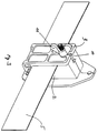
- the insulator has a base 2 which can be screwed to a fence post or the like.
- a flap 3 is articulated in the lower region of the base 2.
- the base 2 has a contact surface 6 for a flat strip 5.
- the flap 3, however, has a contact surface 4. The arrangement is such that the conductor 5 is clamped between the two contact surfaces 4 and 6 when the flap 3 is closed (Fig. 2).
- a locking mechanism 7 is provided in the upper region of the base 2, in the present case in the form of a machine screw 8, the head 9 of which is pivotably mounted in the base 2.
- the screw 8 is pivoted by approximately 90 °, the shaft of the screw 8 being pivoted into an open longitudinal slot 10 in the flap 3 and being screwed by means of a wing screw 11.
- FIG. 1 also shows the special embodiment, which has a notch 12 in the contact surface 6 of the base 2 for receiving an electric cable instead of the flat strip 5 shown.
Landscapes
- Insulators (AREA)
- Processes Specially Adapted For Manufacturing Cables (AREA)
- Catching Or Destruction (AREA)
Applications Claiming Priority (2)
| Application Number | Priority Date | Filing Date | Title |
|---|---|---|---|
| DE9417209U | 1994-10-27 | ||
| DE9417209U DE9417209U1 (de) | 1994-10-27 | 1994-10-27 | Isolator für einen elektrischen Weidezaun |
Publications (1)
| Publication Number | Publication Date |
|---|---|
| EP0709861A1 true EP0709861A1 (fr) | 1996-05-01 |
Family
ID=6915345
Family Applications (1)
| Application Number | Title | Priority Date | Filing Date |
|---|---|---|---|
| EP95116543A Withdrawn EP0709861A1 (fr) | 1994-10-27 | 1995-10-20 | Isolateur pour une clÔture électrique |
Country Status (2)
| Country | Link |
|---|---|
| EP (1) | EP0709861A1 (fr) |
| DE (1) | DE9417209U1 (fr) |
Cited By (1)
| Publication number | Priority date | Publication date | Assignee | Title |
|---|---|---|---|---|
| DE102010008136A1 (de) | 2010-02-16 | 2011-08-18 | Müller, Josef, 84428 | Isolator für einen Elektrozaun |
Families Citing this family (1)
| Publication number | Priority date | Publication date | Assignee | Title |
|---|---|---|---|---|
| DE102008058989A1 (de) * | 2008-11-25 | 2010-06-02 | Karl-Heinz Probst | Weidezaunisolator für Seil und Band (E) Answer Basic CP |
Citations (3)
| Publication number | Priority date | Publication date | Assignee | Title |
|---|---|---|---|---|
| US4356599A (en) * | 1980-12-19 | 1982-11-02 | Minnesota Mining And Manufacturing Company | Stackable flat cable clamp |
| US4965413A (en) * | 1989-08-25 | 1990-10-23 | North Central Plastics, Incorporated | Electric fence insulator with latching capability |
| US5063274A (en) * | 1989-09-29 | 1991-11-05 | Itw Plastiglide | Electric fence insulator |
-
1994
- 1994-10-27 DE DE9417209U patent/DE9417209U1/de not_active Expired - Lifetime
-
1995
- 1995-10-20 EP EP95116543A patent/EP0709861A1/fr not_active Withdrawn
Patent Citations (3)
| Publication number | Priority date | Publication date | Assignee | Title |
|---|---|---|---|---|
| US4356599A (en) * | 1980-12-19 | 1982-11-02 | Minnesota Mining And Manufacturing Company | Stackable flat cable clamp |
| US4965413A (en) * | 1989-08-25 | 1990-10-23 | North Central Plastics, Incorporated | Electric fence insulator with latching capability |
| US5063274A (en) * | 1989-09-29 | 1991-11-05 | Itw Plastiglide | Electric fence insulator |
Cited By (1)
| Publication number | Priority date | Publication date | Assignee | Title |
|---|---|---|---|---|
| DE102010008136A1 (de) | 2010-02-16 | 2011-08-18 | Müller, Josef, 84428 | Isolator für einen Elektrozaun |
Also Published As
| Publication number | Publication date |
|---|---|
| DE9417209U1 (de) | 1994-12-15 |
Similar Documents
| Publication | Publication Date | Title |
|---|---|---|
| DE2709604A1 (de) | Mehrfach-kupplungsbuchse zum anschluss an insbesondere drei steckerstifte | |
| EP0075280B1 (fr) | Borne à vis | |
| DE3938351C2 (de) | Elektrische Klemme | |
| DE29807839U1 (de) | Batterie-Verbindungselement | |
| DE3816010C2 (fr) | ||
| DE2123097A1 (de) | Werkzeughalter für ein Kabelspleißgerät | |
| EP0709861A1 (fr) | Isolateur pour une clÔture électrique | |
| DE1440790B2 (de) | Stecker | |
| DE1100123B (de) | Klemme fuer elektrische Leiter | |
| DE2433347A1 (de) | Elektrische kraftsteckvorrichtung | |
| DE2013884C3 (de) | Steckvorrichtung | |
| EP0827235B1 (fr) | Borne pour barre de masse | |
| EP0271606B1 (fr) | Dispositif de sertissage de connecteurs aux conducteurs d'un câble-ruban | |
| DE2845608C2 (de) | Schutzleiter-Reihenklemme für Tragschienen mit hutförmigem Profil | |
| DE102019218484B4 (de) | Isolator zum Halten eines länglichen, elektrisch leitenden Zaunelements | |
| DE29607495U1 (de) | Vorrichtung zur Zugentlastung von elektrischen Leitungen | |
| EP0133561B1 (fr) | Fiche male pour prises électriques permettant une connexion électriquement conductrice réglable | |
| DE8125479U1 (de) | "Anschlußklemme" | |
| DE1440790C (de) | Stecker | |
| DE9216857U1 (de) | Elektrischer Stecker- und Steckdoseneinheit | |
| DE815360C (de) | Kabelanschlussklemme | |
| DE29918663U1 (de) | Aufhängesockel für eine Lampe | |
| DE4117879C2 (de) | Mit lösbarer Verbindungs- bzw. Anschlußanordnung versehene Drehzahl- bzw. Geschwindigkeitsregelvorrichtung für Elektromotoren | |
| DE6928818U (de) | Ausgangs-zwischenstecker fuer elektrische verteilerschienen | |
| DE2816656C3 (de) | Elektrische Tischleuchte |
Legal Events
| Date | Code | Title | Description |
|---|---|---|---|
| PUAI | Public reference made under article 153(3) epc to a published international application that has entered the european phase |
Free format text: ORIGINAL CODE: 0009012 |
|
| AK | Designated contracting states |
Kind code of ref document: A1 Designated state(s): AT BE CH DE FR LI NL SE |
|
| STAA | Information on the status of an ep patent application or granted ep patent |
Free format text: STATUS: THE APPLICATION HAS BEEN WITHDRAWN |
|
| 18W | Application withdrawn |
Withdrawal date: 19960605 |