EP0709864A2 - Transformateur encapsulé en résine coulée - Google Patents
Transformateur encapsulé en résine coulée Download PDFInfo
- Publication number
- EP0709864A2 EP0709864A2 EP95116433A EP95116433A EP0709864A2 EP 0709864 A2 EP0709864 A2 EP 0709864A2 EP 95116433 A EP95116433 A EP 95116433A EP 95116433 A EP95116433 A EP 95116433A EP 0709864 A2 EP0709864 A2 EP 0709864A2
- Authority
- EP
- European Patent Office
- Prior art keywords
- bore
- connection
- cast resin
- wire
- transformer according
- Prior art date
- Legal status (The legal status is an assumption and is not a legal conclusion. Google has not performed a legal analysis and makes no representation as to the accuracy of the status listed.)
- Granted
Links
- 239000011347 resin Substances 0.000 title claims description 16
- 229920005989 resin Polymers 0.000 title claims description 16
- 238000004804 winding Methods 0.000 claims abstract description 19
- 229910001369 Brass Inorganic materials 0.000 claims abstract description 5
- RYGMFSIKBFXOCR-UHFFFAOYSA-N Copper Chemical compound [Cu] RYGMFSIKBFXOCR-UHFFFAOYSA-N 0.000 claims abstract description 5
- 239000010951 brass Substances 0.000 claims abstract description 5
- 239000010949 copper Substances 0.000 claims abstract description 5
- 229910052802 copper Inorganic materials 0.000 claims abstract description 5
- 238000005266 casting Methods 0.000 description 3
- 239000004020 conductor Substances 0.000 description 3
- 229910000679 solder Inorganic materials 0.000 description 2
- 230000032683 aging Effects 0.000 description 1
- XAGFODPZIPBFFR-UHFFFAOYSA-N aluminium Chemical compound [Al] XAGFODPZIPBFFR-UHFFFAOYSA-N 0.000 description 1
- 229910052782 aluminium Inorganic materials 0.000 description 1
- 150000001875 compounds Chemical class 0.000 description 1
- 238000005516 engineering process Methods 0.000 description 1
- 230000004907 flux Effects 0.000 description 1
- 239000007788 liquid Substances 0.000 description 1
- 238000004519 manufacturing process Methods 0.000 description 1
- 239000000463 material Substances 0.000 description 1
- 238000000034 method Methods 0.000 description 1
- 238000005476 soldering Methods 0.000 description 1
- 238000003466 welding Methods 0.000 description 1
Images

Classifications
-
- H—ELECTRICITY
- H01—ELECTRIC ELEMENTS
- H01F—MAGNETS; INDUCTANCES; TRANSFORMERS; SELECTION OF MATERIALS FOR THEIR MAGNETIC PROPERTIES
- H01F5/00—Coils
- H01F5/04—Arrangements of electric connections to coils, e.g. leads
-
- H—ELECTRICITY
- H01—ELECTRIC ELEMENTS
- H01F—MAGNETS; INDUCTANCES; TRANSFORMERS; SELECTION OF MATERIALS FOR THEIR MAGNETIC PROPERTIES
- H01F27/00—Details of transformers or inductances, in general
- H01F27/02—Casings
- H01F27/022—Encapsulation
-
- H—ELECTRICITY
- H01—ELECTRIC ELEMENTS
- H01F—MAGNETS; INDUCTANCES; TRANSFORMERS; SELECTION OF MATERIALS FOR THEIR MAGNETIC PROPERTIES
- H01F27/00—Details of transformers or inductances, in general
- H01F27/28—Coils; Windings; Conductive connections
Definitions
- the present invention relates to a cast resin transformer with at least one primary winding, at least one secondary winding and at least one with cast-in connection element, which is connected in an electrically conductive manner to the primary winding or the secondary winding via a connecting wire and to which, e.g. by means of a screw connection, a transformer-external connecting line can be connected, the connecting element having a hole for receiving the connecting wire and the connecting wire being inserted into the hole (DE-PS 29 04 746).
- connection elements in which in a casting compound together with the winding cast connection elements are mechanically fixed and electrically conductive via conductor rod to the winding in that these conductor rods have deformations in the manner of a knurling.
- the connecting wires are also connected to the conductor bars via solder joints.
- Similar transformers are also manufactured and sold, for example, by Trafo-Union GmbH under the name GEAFOL cast resin transformers.
- the object of the present invention is to establish a simple, reliable and inexpensive connection between the connecting wire and the connecting element.
- connection technology used allows one reliable operation of the transformer. There is no aging damage like a solder joint.
- the deformation is advantageously designed as a bulge.
- the bulge can be caused by upsetting, which is easy to manufacture.
- the bore can be designed as a blind bore or alternatively as a through bore.
- the connecting element can advantageously have a threaded bore for receiving a screw for connecting the connecting line, the bore being arranged radially or axially to the threaded bore. This allows the cast resin transformer to be connected to the network in a convenient manner.
- the threaded bore and / or the bore can advantageously be arranged eccentrically, so that a lateral connection is possible.
- the connecting element is preferably made of brass, the connecting wire preferably consisting of copper. This ensures good contact.
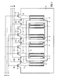
- a primary-side three-phase network with the phases R, S and T or a secondary-side three-phase network with the phases U, V and W can be connected to the connection elements 6 and 8 via transformer-external connecting lines 9, 10.
- the entire transformer including transformer core 4, windings 1, 2, connecting elements 6, 8 and connecting wires 5, 7 is cast in casting resin 11. So only the connection elements 6, 8 are accessible from the outside.
- the windings can also form individually cast structural units which are arranged on a common, non-cast core.
- connection elements 6, 8 are designed as hexagon cast nuts.
- the connection elements 6, 8 each have a threaded bore 12 into which a screw (not shown in FIG. 2) can be screwed.
- a screw not shown in FIG. 2
- the transformer-external connecting lines 9, 10 are connected to the transformer.
- the connection elements 6, 8 also each have a bore 13, which in the cast-in state of the connection elements 6, 8 is directed inwards and serves to accommodate the connection wires 5, 7.
- the connecting wire 5 inserted into the bore 13 has a bulge 14 in the area of the connecting element 6.
- the bulge 14 can e.g. to be caused by upsetting. Due to the bulge 14, the connecting wire 5 is mechanically fixed and electrically conductively connected to the connecting element 6.
- the connection is both gas and liquid tight. It can absorb tensile forces and acts as a protection against torsion.
- the bulge 14 can be designed differently depending on the configuration of the bore 13. If the bore 13 is a simple bore, the bulge 14 is at the entrance to the bore 13 arranged. If the bore is half open or has a puncture, the bulge 14 can alternatively or additionally also be arranged in the semi-open region of the bore 13 or in the puncture region of the bore 13.
- the bore 13 is arranged axially to the threaded bore 12, both the threaded bore 12 and the bore 13 being arranged outside the line of symmetry of the pouring nut 6, that is to say eccentrically. As a result, the pouring nut 6 can be kept compact.
- the bore 13 is designed as a blind bore in the present case.
- the bore 13 could also be designed as a through bore.
- FIG. 3 shows a further embodiment of the connection between connecting wire 7 and connecting element 8.
- the bore 13 is not arranged axially but radially to the threaded bore 12.
- the bore 13 is also formed as a through bore.
- it could also be designed as a blind bore.
- the invention described above is particularly advantageous when the connecting element 6, 8 is made of brass and the connecting wire 5, 7 is made of copper. With this combination in particular, flux is required for soldering, which can only be removed again with great effort. However, other working methods such as welding or squeezing are not possible for other technical reasons.
- the present invention therefore enables great cost savings, in particular in the combination "brass for casting nut and copper for connecting wire".
- other material combinations for example in connection with aluminum, are also possible.
- they are described above Features can be combined in any way within the scope of professional skill, without leaving the path of the present idea.
Landscapes
- Engineering & Computer Science (AREA)
- Power Engineering (AREA)
- Coils Of Transformers For General Uses (AREA)
- Transformers For Measuring Instruments (AREA)
- Coils Or Transformers For Communication (AREA)
- Insulating Of Coils (AREA)
Applications Claiming Priority (2)
| Application Number | Priority Date | Filing Date | Title |
|---|---|---|---|
| DE4438653 | 1994-10-28 | ||
| DE4438653A DE4438653C1 (de) | 1994-10-28 | 1994-10-28 | Gießharztransformator |
Publications (3)
| Publication Number | Publication Date |
|---|---|
| EP0709864A2 true EP0709864A2 (fr) | 1996-05-01 |
| EP0709864A3 EP0709864A3 (fr) | 1996-06-05 |
| EP0709864B1 EP0709864B1 (fr) | 1999-01-13 |
Family
ID=6531985
Family Applications (1)
| Application Number | Title | Priority Date | Filing Date |
|---|---|---|---|
| EP95116433A Expired - Lifetime EP0709864B1 (fr) | 1994-10-28 | 1995-10-18 | Transformateur encapsulé en résine coulée |
Country Status (4)
| Country | Link |
|---|---|
| EP (1) | EP0709864B1 (fr) |
| AT (1) | ATE175806T1 (fr) |
| DE (2) | DE4438653C1 (fr) |
| ES (1) | ES2127451T3 (fr) |
Cited By (1)
| Publication number | Priority date | Publication date | Assignee | Title |
|---|---|---|---|---|
| WO2012123341A3 (fr) * | 2011-03-11 | 2012-12-20 | REO TRAIN TECHNOLOGIES GmbH | Composant électrique comportant au moins une source de dissipation de puissance électrique disposée dans un matériau d'enrobage et un dispositif de refroidissement |
Citations (2)
| Publication number | Priority date | Publication date | Assignee | Title |
|---|---|---|---|---|
| US3838372A (en) | 1971-10-29 | 1974-09-24 | Motorola Inc | Magnetic pickup assembly |
| DE2904746A1 (de) | 1979-02-08 | 1980-08-28 | Smit Transformatoren Bv | Wicklung fuer einen luftgekuehlten trockentransformator |
Family Cites Families (3)
| Publication number | Priority date | Publication date | Assignee | Title |
|---|---|---|---|---|
| DE406685C (de) * | 1923-09-13 | 1925-07-16 | Wolfgang Bauer | Klemme fuer elektrische Leitungen |
| DE3743222A1 (de) * | 1987-12-19 | 1989-06-29 | Asea Brown Boveri | Gekuehlte drosselspule fuer stromrichteranlagen |
| DE9114654U1 (de) * | 1991-11-25 | 1992-04-30 | Elektro-Kern GmbH & Co KG, 7990 Friedrichshafen | Magnetspule |
-
1994
- 1994-10-28 DE DE4438653A patent/DE4438653C1/de not_active Revoked
-
1995
- 1995-10-18 DE DE59504800T patent/DE59504800D1/de not_active Expired - Fee Related
- 1995-10-18 ES ES95116433T patent/ES2127451T3/es not_active Expired - Lifetime
- 1995-10-18 EP EP95116433A patent/EP0709864B1/fr not_active Expired - Lifetime
- 1995-10-18 AT AT95116433T patent/ATE175806T1/de not_active IP Right Cessation
Patent Citations (2)
| Publication number | Priority date | Publication date | Assignee | Title |
|---|---|---|---|---|
| US3838372A (en) | 1971-10-29 | 1974-09-24 | Motorola Inc | Magnetic pickup assembly |
| DE2904746A1 (de) | 1979-02-08 | 1980-08-28 | Smit Transformatoren Bv | Wicklung fuer einen luftgekuehlten trockentransformator |
Cited By (1)
| Publication number | Priority date | Publication date | Assignee | Title |
|---|---|---|---|---|
| WO2012123341A3 (fr) * | 2011-03-11 | 2012-12-20 | REO TRAIN TECHNOLOGIES GmbH | Composant électrique comportant au moins une source de dissipation de puissance électrique disposée dans un matériau d'enrobage et un dispositif de refroidissement |
Also Published As
| Publication number | Publication date |
|---|---|
| EP0709864B1 (fr) | 1999-01-13 |
| ATE175806T1 (de) | 1999-01-15 |
| ES2127451T3 (es) | 1999-04-16 |
| EP0709864A3 (fr) | 1996-06-05 |
| DE59504800D1 (de) | 1999-02-25 |
| DE4438653C1 (de) | 1996-06-20 |
Similar Documents
| Publication | Publication Date | Title |
|---|---|---|
| DE112016000367T5 (de) | Statoraufbau für einen Motor | |
| EP0232471A2 (fr) | Transducteur de courant à haute tension et procédé pour sa fabrication | |
| DE10130982A1 (de) | Temperaturfühler für die Statorwicklung von Elektromotoren | |
| DE2540605B2 (de) | Langgestreckte Einspannhülse aus verformbarem Metall | |
| EP0709864B1 (fr) | Transformateur encapsulé en résine coulée | |
| DE2914540C2 (de) | Ringtransformator für Maschinen zum elektrischen Widerstandsstumpfschweißen | |
| EP1610350A2 (fr) | Transformateur de soudage | |
| CH660088A5 (de) | Scheibenisolator mit eingusselektrode und verfahren zu seiner herstellung. | |
| DE2244158A1 (de) | Drossel oder transformator, insbesondere als vorschaltgeraet fuer gasentladungslampen | |
| DE10145570C2 (de) | Elektromotor | |
| DE725978C (de) | Anordnung der aus Flachband bestehenden Primaerwicklung von Stromwandlern mit Schenkelkern | |
| DE102016215646A1 (de) | Mehrstocktransformator für ein Verteilnetz oder den Betrieb mit einem Umrichter | |
| EP3577665B1 (fr) | Partie active pour un appareil électrique à haute tension | |
| DE2418230C3 (de) | Kapazitiv gesteuerte Hochspannungswicklung aus Scheibenspulen für Transformatoren mit großen Leistungen | |
| DE202014006814U1 (de) | Wicklungsanordnung | |
| DE3239391C2 (fr) | ||
| DE1915864C3 (de) | Drehstromöltransformator | |
| DE2425899A1 (de) | Wicklungsanordnung fuer transformatoren mit rechteckigem kernquerschnitt | |
| EP0102941B1 (fr) | Enroulement à conducteurs transposés | |
| DE2513393C3 (de) | Hochspannungsstromwandler | |
| DE102017204930B4 (de) | Elektrisches Gerät zum Anschluss an ein Hochspannungsnetz | |
| DE19829761A1 (de) | Verfahren und Leitungsverbinder zum Verbinden von warmfest lackisolierten Drähten | |
| DE2161635A1 (de) | Drossel oder transformator, insbesondere als vorschaltgeraet fuer gasentladungslampen | |
| EP0967690B1 (fr) | Procédé de raccordement de fils mince avec un élément de contact conduisant de courant et produits ainsi obtenus | |
| DE19609260C2 (de) | Isolationsanordnung für rechteckige Wickeldrähte zur Herstellung von Wicklungen aus Scheibenspulen für Transformatoren und Drosseln |
Legal Events
| Date | Code | Title | Description |
|---|---|---|---|
| PUAI | Public reference made under article 153(3) epc to a published international application that has entered the european phase |
Free format text: ORIGINAL CODE: 0009012 |
|
| PUAL | Search report despatched |
Free format text: ORIGINAL CODE: 0009013 |
|
| AK | Designated contracting states |
Kind code of ref document: A2 Designated state(s): AT BE CH DE ES FR GB IT LI NL PT SE |
|
| AK | Designated contracting states |
Kind code of ref document: A3 Designated state(s): AT BE CH DE ES FR GB IT LI NL PT SE |
|
| 17P | Request for examination filed |
Effective date: 19960706 |
|
| 17Q | First examination report despatched |
Effective date: 19960821 |
|
| GRAG | Despatch of communication of intention to grant |
Free format text: ORIGINAL CODE: EPIDOS AGRA |
|
| GRAG | Despatch of communication of intention to grant |
Free format text: ORIGINAL CODE: EPIDOS AGRA |
|
| GRAH | Despatch of communication of intention to grant a patent |
Free format text: ORIGINAL CODE: EPIDOS IGRA |
|
| GRAH | Despatch of communication of intention to grant a patent |
Free format text: ORIGINAL CODE: EPIDOS IGRA |
|
| GRAA | (expected) grant |
Free format text: ORIGINAL CODE: 0009210 |
|
| AK | Designated contracting states |
Kind code of ref document: B1 Designated state(s): AT BE CH DE ES FR GB IT LI NL PT SE |
|
| PG25 | Lapsed in a contracting state [announced via postgrant information from national office to epo] |
Ref country code: SE Free format text: THE PATENT HAS BEEN ANNULLED BY A DECISION OF A NATIONAL AUTHORITY Effective date: 19990113 |
|
| REF | Corresponds to: |
Ref document number: 175806 Country of ref document: AT Date of ref document: 19990115 Kind code of ref document: T |
|
| REG | Reference to a national code |
Ref country code: CH Ref legal event code: NV Representative=s name: SIEMENS SCHWEIZ AG Ref country code: CH Ref legal event code: EP |
|
| REF | Corresponds to: |
Ref document number: 59504800 Country of ref document: DE Date of ref document: 19990225 |
|
| ET | Fr: translation filed | ||
| ITF | It: translation for a ep patent filed | ||
| REG | Reference to a national code |
Ref country code: ES Ref legal event code: FG2A Ref document number: 2127451 Country of ref document: ES Kind code of ref document: T3 |
|
| GBT | Gb: translation of ep patent filed (gb section 77(6)(a)/1977) |
Effective date: 19990524 |
|
| PG25 | Lapsed in a contracting state [announced via postgrant information from national office to epo] |
Ref country code: AT Free format text: LAPSE BECAUSE OF NON-PAYMENT OF DUE FEES Effective date: 19991018 |
|
| PG25 | Lapsed in a contracting state [announced via postgrant information from national office to epo] |
Ref country code: ES Free format text: LAPSE BECAUSE OF NON-PAYMENT OF DUE FEES Effective date: 19991019 |
|
| PLBE | No opposition filed within time limit |
Free format text: ORIGINAL CODE: 0009261 |
|
| STAA | Information on the status of an ep patent application or granted ep patent |
Free format text: STATUS: NO OPPOSITION FILED WITHIN TIME LIMIT |
|
| 26N | No opposition filed | ||
| PG25 | Lapsed in a contracting state [announced via postgrant information from national office to epo] |
Ref country code: NL Free format text: LAPSE BECAUSE OF NON-PAYMENT OF DUE FEES Effective date: 20000501 |
|
| EUG | Se: european patent has lapsed |
Ref document number: 95116433.4 |
|
| NLV4 | Nl: lapsed or anulled due to non-payment of the annual fee |
Effective date: 20000501 |
|
| PG25 | Lapsed in a contracting state [announced via postgrant information from national office to epo] |
Ref country code: PT Free format text: LAPSE BECAUSE OF NON-PAYMENT OF DUE FEES Effective date: 20010430 |
|
| REG | Reference to a national code |
Ref country code: GB Ref legal event code: IF02 |
|
| REG | Reference to a national code |
Ref country code: ES Ref legal event code: FD2A Effective date: 20001113 |
|
| PGFP | Annual fee paid to national office [announced via postgrant information from national office to epo] |
Ref country code: BE Payment date: 20041020 Year of fee payment: 10 |
|
| PG25 | Lapsed in a contracting state [announced via postgrant information from national office to epo] |
Ref country code: BE Free format text: LAPSE BECAUSE OF NON-PAYMENT OF DUE FEES Effective date: 20051031 |
|
| BERE | Be: lapsed |
Owner name: *SIEMENS A.G. Effective date: 20051031 |
|
| PGFP | Annual fee paid to national office [announced via postgrant information from national office to epo] |
Ref country code: CH Payment date: 20080110 Year of fee payment: 13 |
|
| PGFP | Annual fee paid to national office [announced via postgrant information from national office to epo] |
Ref country code: DE Payment date: 20071214 Year of fee payment: 13 |
|
| PG25 | Lapsed in a contracting state [announced via postgrant information from national office to epo] |
Ref country code: PT Free format text: LAPSE BECAUSE OF NON-PAYMENT OF DUE FEES Effective date: 19991018 |
|
| REG | Reference to a national code |
Ref country code: CH Ref legal event code: PCAR Free format text: SIEMENS SCHWEIZ AG;INTELLECTUAL PROPERTY FREILAGERSTRASSE 40;8047 ZUERICH (CH) |
|
| PGFP | Annual fee paid to national office [announced via postgrant information from national office to epo] |
Ref country code: IT Payment date: 20081028 Year of fee payment: 14 |
|
| PGFP | Annual fee paid to national office [announced via postgrant information from national office to epo] |
Ref country code: FR Payment date: 20081017 Year of fee payment: 14 |
|
| REG | Reference to a national code |
Ref country code: CH Ref legal event code: PL |
|
| PGFP | Annual fee paid to national office [announced via postgrant information from national office to epo] |
Ref country code: GB Payment date: 20081020 Year of fee payment: 14 |
|
| PG25 | Lapsed in a contracting state [announced via postgrant information from national office to epo] |
Ref country code: DE Free format text: LAPSE BECAUSE OF NON-PAYMENT OF DUE FEES Effective date: 20090501 |
|
| PG25 | Lapsed in a contracting state [announced via postgrant information from national office to epo] |
Ref country code: LI Free format text: LAPSE BECAUSE OF NON-PAYMENT OF DUE FEES Effective date: 20081031 Ref country code: CH Free format text: LAPSE BECAUSE OF NON-PAYMENT OF DUE FEES Effective date: 20081031 |
|
| REG | Reference to a national code |
Ref country code: FR Ref legal event code: ST Effective date: 20100630 |
|
| PG25 | Lapsed in a contracting state [announced via postgrant information from national office to epo] |
Ref country code: FR Free format text: LAPSE BECAUSE OF NON-PAYMENT OF DUE FEES Effective date: 20091102 |
|
| PG25 | Lapsed in a contracting state [announced via postgrant information from national office to epo] |
Ref country code: GB Free format text: LAPSE BECAUSE OF NON-PAYMENT OF DUE FEES Effective date: 20091018 |
|
| PG25 | Lapsed in a contracting state [announced via postgrant information from national office to epo] |
Ref country code: IT Free format text: LAPSE BECAUSE OF NON-PAYMENT OF DUE FEES Effective date: 20091018 |