EP0709885A2 - Baugruppe mit integriertem, geschlossenem Kühlkreislaufsystem - Google Patents
Baugruppe mit integriertem, geschlossenem Kühlkreislaufsystem Download PDFInfo
- Publication number
- EP0709885A2 EP0709885A2 EP95307538A EP95307538A EP0709885A2 EP 0709885 A2 EP0709885 A2 EP 0709885A2 EP 95307538 A EP95307538 A EP 95307538A EP 95307538 A EP95307538 A EP 95307538A EP 0709885 A2 EP0709885 A2 EP 0709885A2
- Authority
- EP
- European Patent Office
- Prior art keywords
- cooling
- heat
- delivery system
- cooling fluid
- manifold
- Prior art date
- Legal status (The legal status is an assumption and is not a legal conclusion. Google has not performed a legal analysis and makes no representation as to the accuracy of the status listed.)
- Withdrawn
Links
Images


Classifications
-
- H—ELECTRICITY
- H05—ELECTRIC TECHNIQUES NOT OTHERWISE PROVIDED FOR
- H05K—PRINTED CIRCUITS; CASINGS OR CONSTRUCTIONAL DETAILS OF ELECTRIC APPARATUS; MANUFACTURE OF ASSEMBLAGES OF ELECTRICAL COMPONENTS
- H05K7/00—Constructional details common to different types of electric apparatus
- H05K7/20—Modifications to facilitate cooling, ventilating, or heating
- H05K7/20009—Modifications to facilitate cooling, ventilating, or heating using a gaseous coolant in electronic enclosures
- H05K7/20136—Forced ventilation, e.g. by fans
- H05K7/20145—Means for directing air flow, e.g. ducts, deflectors, plenum or guides
-
- H—ELECTRICITY
- H10—SEMICONDUCTOR DEVICES; ELECTRIC SOLID-STATE DEVICES NOT OTHERWISE PROVIDED FOR
- H10W—GENERIC PACKAGES, INTERCONNECTIONS, CONNECTORS OR OTHER CONSTRUCTIONAL DETAILS OF DEVICES COVERED BY CLASS H10
- H10W40/00—Arrangements for thermal protection or thermal control
- H10W40/40—Arrangements for thermal protection or thermal control involving heat exchange by flowing fluids
- H10W40/43—Arrangements for thermal protection or thermal control involving heat exchange by flowing fluids by flowing gases, e.g. forced air cooling
-
- H—ELECTRICITY
- H05—ELECTRIC TECHNIQUES NOT OTHERWISE PROVIDED FOR
- H05K—PRINTED CIRCUITS; CASINGS OR CONSTRUCTIONAL DETAILS OF ELECTRIC APPARATUS; MANUFACTURE OF ASSEMBLAGES OF ELECTRICAL COMPONENTS
- H05K1/00—Printed circuits
- H05K1/18—Printed circuits structurally associated with non-printed electric components
-
- H—ELECTRICITY
- H10—SEMICONDUCTOR DEVICES; ELECTRIC SOLID-STATE DEVICES NOT OTHERWISE PROVIDED FOR
- H10W—GENERIC PACKAGES, INTERCONNECTIONS, CONNECTORS OR OTHER CONSTRUCTIONAL DETAILS OF DEVICES COVERED BY CLASS H10
- H10W40/00—Arrangements for thermal protection or thermal control
- H10W40/40—Arrangements for thermal protection or thermal control involving heat exchange by flowing fluids
- H10W40/47—Arrangements for thermal protection or thermal control involving heat exchange by flowing fluids by flowing liquids, e.g. forced water cooling
-
- H—ELECTRICITY
- H05—ELECTRIC TECHNIQUES NOT OTHERWISE PROVIDED FOR
- H05K—PRINTED CIRCUITS; CASINGS OR CONSTRUCTIONAL DETAILS OF ELECTRIC APPARATUS; MANUFACTURE OF ASSEMBLAGES OF ELECTRICAL COMPONENTS
- H05K2201/00—Indexing scheme relating to printed circuits covered by H05K1/00
- H05K2201/06—Thermal details
- H05K2201/064—Fluid cooling, e.g. by integral pipes
Definitions
- This invention relates to the cooling of heat-producing devices. More particularly, this invention relates to a circuit pack having an integrated closed-loop cooling system.
- Effectively dissipating the heat produced by the operation of microelectronic devices, such as integrated circuit (“ICs"), is an important concern in optimizing the performance of the circuitry in which those devices are used.
- effective heat dissipation also helps to prolong the useful life of those devices and enhances both device and overall system reliability.
- IC devices typically include an active semiconductor die encapsulated in a plastic package.
- the plastic package provides mechanical protection to the die and dissipates heat generated by the die during operation.
- One or more IC devices are electrically interconnected and mounted on a common substrate, such as a printed circuit board, to form a circuit pack.
- a heat sink typically made of metal having high thermal conductivity, may be attached to the outer surface of each of the packages to aid in heat dissipation.
- Such heat sinks often utilize an array of elongated fins arranged on a common platform where the platform is then bonded or mechanically attached to the top of the IC package.
- Cooling fluid such as air, conducts heat away from the IC package and heat sink by means of forced or natural convection. Unfortunately, such cooling arrangements afford limited cooling capacity and thus, may not be able to adequately dissipate the heat generated by today's high-powered circuit packs in certain applications.
- circuit pack with an integrated closed-loop cooling system, such a circuit pack comprising: a substrate; at least one heat-producing component mounted on the substrate; cooling units provided for predetermined ones of at least one heat-producing component in heat conductive relationship therewith; a delivery system for delivery of a cooling fluid to and from the cooling units; and a cooling fluid mover coupled to the substrate for circulating the cooling fluid through the delivery system and the cooling units.
- a heat exchanger and cooling fluid reservoir are coupled to the delivery system to enhance the performance of the integrated closed-loop cooling system in certain applications of the invention.
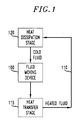
- FIG. 1 is a simplified block diagram of a closed-loop cooling system, the principles of which are embodied in the present invention.
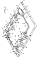
- FIG. 2 is a pictorial representation of an illustrative example of a circuit pack having an integrated closed-loop cooling system, in accordance with the invention.
- FIG. 3 is a simplified schematic diagram of the circuit pack shown in FIG. 2.
- FIG. 4 shows an illustrative example of the invention having a heat exchanger and cooling fluid reservoir.
- FIG. 5 shows an illustrative example of the invention with a manifold delivery system.
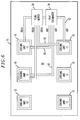
- FIG. 6 shows an illustrative example of the invention with a multiple-loop delivery system.
- FIG. 1 is a simplified block diagram of a closed-loop cooling system, the principles of which are embodied in the present invention.
- a fluid is continously circulated by a fluid moving device 100 around a closed-loop 110 coupling a heat transfer stage 115 and a heat dissipation stage 120.
- the system is "closed” because cooling fluid never leaves the system.
- Heat, from some heat source (not shown) is transferred to the fluid in the heat transfer stage 115 and dissipated by the fluid in the heat dissipation stage 120.
- FIG. 2 is a simplified pictorial representation of an illustrative example of a circuit pack 5 having an integrated closed-loop cooling system, in accordance with the invention.
- FIG. 3 is a simplified schematic diagram of circuit pack 5.
- circuit-pack refers to devices which typically comprise a plurality of electrically interconnected integrated circuits ("ICs") mounted on a common substrate such as a printed circuit board. These devices are often called “cards” or “boards” and are typically installed in slots in some larger electronic system such as computers, televisions, telephone switches, and the like. Modem cards and video boards for personal computers are well known examples of circuit packs.
- integrated closed-loop cooling system refers to an arrangement where a complete closed-loop cooling system is directly incorporated into the circuit pack without requiring connections, other than power, to systems or components external to the circuit pack in order to perform the desired cooling function. It should also be noted that heretofore closed-loop cooling has been provided to heat-producing components using apparatus that is at least partially remotely located from the circuit pack and typically centralized so as to provide electronic system-level cooling for components located on different circuit packs.
- the circuit pack having an integrated closed-loop cooling system of the present invention provides a number of advantages: 1) Simplified electronic system repair - If a particular circuit pack in the system fails, a replacement circuit pack can be readily installed since no plumbing connections need to be broken or made to a central cooling system to effectuate the replacement.
- circuit pack 5 While it is intended that the various components of circuit pack 5, which are discussed in detail below, be sufficiently miniature to effect a closed-loop cooling system that is integrated on a circuit pack, it will be appreciated by those skilled in the art that the specific size and dimensions of the various components, as well as operating parameters such pressure and flow rates, are dependent upon the particular application of the invention. Accordingly, specific component sizes and dimensions and operating parameters may be readily selected based on generally known principles of heat transfer and fluid dynamics.
- a circuit pack 5 includes a plurality of heat-producing components 10 which are located on a substrate 15.
- Circuit pack 5 may also include various other electrical and mechanical components (not shown) that are typically employed in circuit packs.
- Heat-producing components 10 could be, for example, integrated circuit devices.
- Substrate 15 would typically be a printed circuit board.
- Each of the heat producing components 10 is equipped with a cooling unit 12 that is in heat conductive contact with the heat-producing component. Cooling units are devices that remove heat from heat-producing electronic components, and often have provision for utilizing a cooling fluid of some kind.
- Cooling units are well known and include, for example, cooling members as described in United States patent 4,558,395 by Yamada et al., the disclosure of which is incorporated by reference herein. Alternatively, cooling units may be, for example, integrated into the package of components 10 as described in my co-pending United States application Serial Number (K. Azar Case 13), filed on the same day as the present application, the disclosure of which is incorporated by reference herein. Cooling units 12 may be formed, for example, using metals having high thermal conductivity such as copper, steel, and aluminum. Alternatively, cooling units 12 may be formed using plastic, glass, or ceramic materials. Although each heat-producing component 10 is shown with its own individual cooling unit 12, it should also be noted that a cooling unit 12 may be sized and located to provide cooling to more than one heat-producing component 10.
- Circuit pack 5 also includes a delivery system 20, which in this illustrative example of the invention, comprises a plurality of cooling pipe segments 22 serially connected between adjacent cooling units 12.
- Cooling pipe segments 22 may be formed from any of the many tubing types that are known in art for their ability to carrying cooling fluids. Accordingly, cooling pipe segments 22 may be, for example, steel, stainless steel, copper, aluminum, plastic, or combinations thereof. Cooling pipe segments 22 are coupled to cooling units 12 in a fluid-tight manner. For example, the coupling could be threaded, adhesive-bonded, brazed, welded, soldered, friction-fit, molded, or press-fit according to the particular materials chosen for cooling units 12 and cooling pipe segments 22.
- Cooling fluid mover 26 having an intake port 27 and discharge port 28, is coupled via these ports, as shown, to cooling pipe segments 22 to effect a single pass closed-loop cooling system.
- Cooling fluid mover 26 may be, for example, a pump, siphon, turbine, or compressor. These devices, having appropriate sizes for application to the present invention, are known.
- Cooling fluid mover 26 circulates a cooling fluid (not shown) through cooling pipe segments 22 and cooling units 12 in a continuous loop so that heat generated by the heat-producing components 10 is transferred to the cooling fluid in cooling units 12.
- the cooling fluid can be a gas or liquid.
- the cooling fluid is a liquid, such as water, due to its greater thermal conductivity as compared to gases.
- One suitable liquid cooling fluid is commercially available under the designation FLUORINERT FC-77 by the 3M Corporation.
- cooling pipe segments 22 and cooling fluid mover 26 the heat carried by the cooling fluid will be dissipated to the ambient surroundings via natural convection as it circulates through cooling pipe segments 22 and cooling fluid mover 26.
- this heat dissipation can be substantial, particularly if forced convection is utilized.
- external heat sinks may be attached to cooling pipe segments 22 and cooling fluid mover 26 to increase the effective heat dissipative surface area for these components.
- Heat exchangers are well known, and may include, for example, coiled tube, finned tube, plates, shell and tube, and U-tube designs.
- Heat exchanger 34 as shown in FIG. 4 is multiple row finned tube design. Heat exchanger 34 may be air or liquid cooled. If air cooled, then natural or forced convection may be utilized.
- Cooling fluid reservoir 36 serves to increase the volume of fluid available for cooling purposes thereby increasing the cooling capacity of the cooling system, and may be used to promote mixing between cooling fluid returning from cooling units 12 and the cooling fluid held in the reservoir 36.
- cooling fluid reservoirs are known.
- Conventional heat sinks may be attached to the exterior of cooling fluid reservoir 36 to provide a further heat dissipation path for the cooling fluid, if desired.
- Cooling fluid reservoir 36 may also be equipped with known filter arrangements to remove contaminants or other foreign substances from cooling fluid 32.
- FIG. 5 shows another illustrative arrangement of a delivery system, in accordance with the invention.
- Delivery system 80 comprises a main supply manifold 82 and main return manifold 83.
- Heat exchanger 34 is also shown in FIG. 5.
- Secondary supply lines 84 and secondary return lines 86 couple the main supply manifold 82 and main return manifold 83, respectively, to the individual cooling units 12 as shown.
- Cold cooling fluid is discharged from fluid mover 26 into the main supply manifold 82 where it is circulated through the cooling units 12. The hot cooling fluid is then returned to heat exchanger 34 via main return manifold 83 as shown.
- the manifolds and supply lines may be formed from the same materials as the cooling pipe segments 22 described when referring to FIG. 2.
- the above described manifold delivery arrangement may be useful, for example, in situations where the layout of the heat-producing components 10 on substrate 15 is such as to prevent serial connection of the cooling pipes.
- a manifold delivery arrangement may be desirable for the uniform cooling it provides to cooling units 12, recognizing of course, that the above-described single pass system may provide non-uniform cooling in certain instances.
- FIG. 6 shows another illustrative arrangement of a delivery system, in accordance with the invention.
- Delivery system 90 comprises a plurality of cooling loops 92 where each cooling loop couples individual cooling units 12 to fluid mover 26 and heat exchanger 34 as shown to effect a multiple-loop delivery system. For clarity in illustration, only three cooling units 12 are shown coupled to the delivery system.
- Such a delivery system may be useful in order to accomodate particular circuit pack layouts that are not suited to the above-described single-pass and manifold delivery system.
- multiple fluid movers, cooling fluid reservoirs, and heat exchangers may also be incorporated onto a single circuit pack.
Landscapes
- Engineering & Computer Science (AREA)
- Microelectronics & Electronic Packaging (AREA)
- Physics & Mathematics (AREA)
- Thermal Sciences (AREA)
- Cooling Or The Like Of Semiconductors Or Solid State Devices (AREA)
- Cooling Or The Like Of Electrical Apparatus (AREA)
Applications Claiming Priority (2)
| Application Number | Priority Date | Filing Date | Title |
|---|---|---|---|
| US33222394A | 1994-10-31 | 1994-10-31 | |
| US332223 | 1994-10-31 |
Publications (2)
| Publication Number | Publication Date |
|---|---|
| EP0709885A2 true EP0709885A2 (de) | 1996-05-01 |
| EP0709885A3 EP0709885A3 (de) | 1997-08-27 |
Family
ID=23297269
Family Applications (1)
| Application Number | Title | Priority Date | Filing Date |
|---|---|---|---|
| EP95307538A Withdrawn EP0709885A3 (de) | 1994-10-31 | 1995-10-24 | Baugruppe mit integriertem, geschlossenem Kühlkreislaufsystem |
Country Status (5)
| Country | Link |
|---|---|
| EP (1) | EP0709885A3 (de) |
| JP (1) | JPH08213526A (de) |
| KR (1) | KR960015698A (de) |
| AU (1) | AU3446195A (de) |
| CA (1) | CA2161823A1 (de) |
Cited By (4)
| Publication number | Priority date | Publication date | Assignee | Title |
|---|---|---|---|---|
| WO1998003997A1 (en) * | 1996-07-22 | 1998-01-29 | Northrop Grumman Corporation | Closed loop liquid cooling within rf modules |
| CN104487794A (zh) * | 2012-09-05 | 2015-04-01 | 松下知识产权经营株式会社 | 冷却装置、装载有该冷却装置的电动汽车和电子设备 |
| US9279340B2 (en) | 2010-03-23 | 2016-03-08 | General Electric Company | System and method for cooling gas turbine components |
| US10756002B2 (en) | 2018-01-15 | 2020-08-25 | Stmicroelectronics S.R.L. | Packaged power device having improved heat dissipation capacity and better thermal performances |
Families Citing this family (2)
| Publication number | Priority date | Publication date | Assignee | Title |
|---|---|---|---|---|
| US7280358B2 (en) * | 2004-04-19 | 2007-10-09 | Hewlett-Packard Development Company, L.P. | Liquid loop with multiple heat exchangers for efficient space utilization |
| JP2014116385A (ja) * | 2012-12-07 | 2014-06-26 | Panasonic Corp | 冷却装置およびこれを搭載した電気自動車および電子機器 |
Citations (1)
| Publication number | Priority date | Publication date | Assignee | Title |
|---|---|---|---|---|
| US4558395A (en) | 1983-04-27 | 1985-12-10 | Hitachi, Ltd. | Cooling module for integrated circuit chips |
Family Cites Families (7)
| Publication number | Priority date | Publication date | Assignee | Title |
|---|---|---|---|---|
| US4791983A (en) * | 1987-10-13 | 1988-12-20 | Unisys Corporation | Self-aligning liquid-cooling assembly |
| JPH0682941B2 (ja) * | 1987-10-22 | 1994-10-19 | 富士通株式会社 | 冷却液供給装置 |
| JPH03208398A (ja) * | 1990-01-10 | 1991-09-11 | Fujitsu Ltd | 半導体装置 |
| US5177666A (en) * | 1991-10-24 | 1993-01-05 | Bland Timothy J | Cooling rack for electronic devices |
| JPH05121610A (ja) * | 1991-10-29 | 1993-05-18 | Nec Commun Syst Ltd | 液体冷却方式 |
| US5316077A (en) * | 1992-12-09 | 1994-05-31 | Eaton Corporation | Heat sink for electrical circuit components |
| JPH0794648A (ja) * | 1993-09-27 | 1995-04-07 | Hitachi Ltd | 集積回路の冷却装置 |
-
1995
- 1995-10-24 EP EP95307538A patent/EP0709885A3/de not_active Withdrawn
- 1995-10-25 AU AU34461/95A patent/AU3446195A/en not_active Abandoned
- 1995-10-30 KR KR1019950039470A patent/KR960015698A/ko not_active Withdrawn
- 1995-10-31 CA CA002161823A patent/CA2161823A1/en not_active Abandoned
- 1995-10-31 JP JP7305274A patent/JPH08213526A/ja active Pending
Patent Citations (1)
| Publication number | Priority date | Publication date | Assignee | Title |
|---|---|---|---|---|
| US4558395A (en) | 1983-04-27 | 1985-12-10 | Hitachi, Ltd. | Cooling module for integrated circuit chips |
Cited By (5)
| Publication number | Priority date | Publication date | Assignee | Title |
|---|---|---|---|---|
| WO1998003997A1 (en) * | 1996-07-22 | 1998-01-29 | Northrop Grumman Corporation | Closed loop liquid cooling within rf modules |
| US9279340B2 (en) | 2010-03-23 | 2016-03-08 | General Electric Company | System and method for cooling gas turbine components |
| CN104487794A (zh) * | 2012-09-05 | 2015-04-01 | 松下知识产权经营株式会社 | 冷却装置、装载有该冷却装置的电动汽车和电子设备 |
| CN104487794B (zh) * | 2012-09-05 | 2017-03-08 | 松下知识产权经营株式会社 | 冷却装置、装载有该冷却装置的电动汽车和电子设备 |
| US10756002B2 (en) | 2018-01-15 | 2020-08-25 | Stmicroelectronics S.R.L. | Packaged power device having improved heat dissipation capacity and better thermal performances |
Also Published As
| Publication number | Publication date |
|---|---|
| KR960015698A (ko) | 1996-05-22 |
| JPH08213526A (ja) | 1996-08-20 |
| EP0709885A3 (de) | 1997-08-27 |
| CA2161823A1 (en) | 1996-05-01 |
| AU3446195A (en) | 1996-05-09 |
Similar Documents
| Publication | Publication Date | Title |
|---|---|---|
| US7327570B2 (en) | Fluid cooled integrated circuit module | |
| KR102930582B1 (ko) | 열 관리 장치를 포함하는 이종 통합 모듈 | |
| US5986882A (en) | Electronic apparatus having removable processor/heat pipe cooling device modules therein | |
| US6055157A (en) | Large area, multi-device heat pipe for stacked MCM-based systems | |
| US6173759B1 (en) | Method of cooling electronic devices using a tube in plate heat sink | |
| US8713957B2 (en) | Thermoelectric-enhanced, vapor-condenser facilitating immersion-cooling of electronic component(s) | |
| US8369091B2 (en) | Interleaved, immersion-cooling apparatus and method for an electronic subsystem of an electronics rack | |
| US9686889B2 (en) | Field-replaceable bank of immersion-cooled electronic components | |
| US6496367B2 (en) | Apparatus for liquid cooling of specific computer components | |
| US7715194B2 (en) | Methodology of cooling multiple heat sources in a personal computer through the use of multiple fluid-based heat exchanging loops coupled via modular bus-type heat exchangers | |
| US5982616A (en) | Electronic apparatus with plug-in heat pipe module cooling system | |
| US9250024B2 (en) | Pump-enhanced, sub-cooling of immersion-cooling fluid | |
| US7515415B2 (en) | Embedded microchannel cooling package for a central processor unit | |
| US9282678B2 (en) | Field-replaceable bank of immersion-cooled electronic components and separable heat sinks | |
| US5699853A (en) | Combined heat sink and sink plate | |
| US20110315343A1 (en) | Interleaved, immersion-cooling apparatuses and methods for cooling electronic subsystems | |
| US20060162898A1 (en) | Liquid cooled thermosiphon with flexible coolant tubes | |
| US6377459B1 (en) | Chip cooling management | |
| US20050241802A1 (en) | Liquid loop with flexible fan assembly | |
| US20110315355A1 (en) | Immersion-cooling apparatus and method for an electronic subsystem of an electronics rack | |
| US20100103619A1 (en) | Interchangeable Heat Exchanger for a Circuit Board | |
| CN102834688A (zh) | 相变冷却器和设有该相变冷却器的电子设备 | |
| JP2009532871A (ja) | 冷却装置 | |
| US7755186B2 (en) | Cooling solutions for die-down integrated circuit packages | |
| US10874034B1 (en) | Pump driven liquid cooling module with tower fins |
Legal Events
| Date | Code | Title | Description |
|---|---|---|---|
| PUAI | Public reference made under article 153(3) epc to a published international application that has entered the european phase |
Free format text: ORIGINAL CODE: 0009012 |
|
| AK | Designated contracting states |
Kind code of ref document: A2 Designated state(s): DE FR GB IT NL SE |
|
| PUAL | Search report despatched |
Free format text: ORIGINAL CODE: 0009013 |
|
| AK | Designated contracting states |
Kind code of ref document: A3 Designated state(s): DE FR GB IT NL SE |
|
| 17P | Request for examination filed |
Effective date: 19980211 |
|
| STAA | Information on the status of an ep patent application or granted ep patent |
Free format text: STATUS: THE APPLICATION HAS BEEN WITHDRAWN |
|
| 17Q | First examination report despatched |
Effective date: 19990105 |
|
| 18W | Application withdrawn |
Withdrawal date: 19990109 |