EP0709921A1 - Barrette d'interconnexion pour repartition transversale de puissance - Google Patents
Barrette d'interconnexion pour repartition transversale de puissance Download PDFInfo
- Publication number
- EP0709921A1 EP0709921A1 EP95113953A EP95113953A EP0709921A1 EP 0709921 A1 EP0709921 A1 EP 0709921A1 EP 95113953 A EP95113953 A EP 95113953A EP 95113953 A EP95113953 A EP 95113953A EP 0709921 A1 EP0709921 A1 EP 0709921A1
- Authority
- EP
- European Patent Office
- Prior art keywords
- distribution
- jumper
- conductor
- plug
- connection
- Prior art date
- Legal status (The legal status is an assumption and is not a legal conclusion. Google has not performed a legal analysis and makes no representation as to the accuracy of the status listed.)
- Granted
Links
Images


Classifications
-
- H—ELECTRICITY
- H01—ELECTRIC ELEMENTS
- H01R—ELECTRICALLY-CONDUCTIVE CONNECTIONS; STRUCTURAL ASSOCIATIONS OF A PLURALITY OF MUTUALLY-INSULATED ELECTRICAL CONNECTING ELEMENTS; COUPLING DEVICES; CURRENT COLLECTORS
- H01R9/00—Structural associations of a plurality of mutually-insulated electrical connecting elements, e.g. terminal strips or terminal blocks; Terminals or binding posts mounted upon a base or in a case; Bases therefor
- H01R9/22—Bases, e.g. strip, block, panel
- H01R9/24—Terminal blocks
- H01R9/26—Clip-on terminal blocks for side-by-side rail- or strip-mounting
- H01R9/2675—Electrical interconnections between two blocks, e.g. by means of busbars
Definitions
- the invention relates to distribution strips with a plurality of conductor connections which are arranged next to one another and contain conductor rail pieces and have a distribution of the electrical power.
- distribution strips are used for the supply-related and control-related connection of technical components such as voltage sources, signal receivers, initiators, actuators and field devices. They can be used to build up initiator terminal blocks (EP 0 222 030 A1). They are also widely used in modular control systems.
- a large number of solutions for jumper elements are known from the prior art which provide suitable devices for connecting conductor connections within a row direction of a distributor strip in order to transmit potentials between the distributor strips in the row direction.
- These so-called cross distributors are known for example from DE 43 22 535 A1, DE 30 48 497 A1, DE 68 91 20 40 T2.
- the transverse distribution is carried out exclusively within a distribution strip, in which, due to the connection situation of the connected components, certain potentials are required at the connection points. In this case, however, the forwarding of the potentials, which is usually referred to as transverse distribution, does not leave the distributor strip, only connecting elements are connected to one another in the direction of the row.
- the present invention is based on the object of demonstrating an embodiment with which distribution strips arranged parallel to one another reliably and simply, at least in some areas, with the possibility of additional potential branching to the same potential can be brought.
- the solution according to the invention consists in that at least one conductor connection of a distribution strip and the adjacent conductor connection of at least one distribution strip arranged parallel to one another have bottom-side plug contact elements on their conductor rail pieces for an additional potential branching for transverse distribution and a jumper is provided which has a contact spring strut with which the bottom side is connected Plug contact element of the current conducting piece contacting a conductor connection can be contacted and the jumper has at least one plug contact element with which the bottom-side plug contact element of the adjacent other conductor connection of the distribution strip can be contacted.
- socket contacts and plug-in tabs are arranged on the side in such a way that the plug-in tabs contact the socket contacts in the direction of the sequence of adjacent conductor connections in the sequence in order to form the distribution strip, the socket contacts forming the bottom-side plug contact elements are also open to the floor.
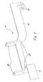
- FIG. 1 shows two connecting disks 1 and 2 of a connecting block composed of a plurality of such connecting disks, for example a modular control system, in this exemplary embodiment the connecting disk 2 being the connecting disk on the input side with respect to the transverse potential distribution and potential branching, which in the illustrated embodiment also has a first modular design Distribution strips 3 in corresponding receptacles 4 in the disc housing 5 carries.
- the individual elements of the distributor strips 3 consist essentially of electrically conductive conductor connections 6, which are located in a housing washer 7, which is on one of them Side are provided with locking pin 8 and on the other side with locking recesses, so that in this way the distribution strip is built up in the desired number of poles in connection with the arrangement and composition.
- socket contacts 10 are designed as spring-loaded terminals, busbar pieces 9, which all have lateral socket contacts 10 on the one hand and plug-in tabs 11 on the other hand, in such an arrangement that when assembling the distribution strips in each of the individual distribution strips 3, the plug-in tabs 11 contacting the socket contacts 10 of adjacent conductor connections 6 intervene.
- the socket contacts 10 are also open at the bottom and thus at the same time form a plug contact element on the bottom, for which free access is also provided in the bottom region of the housing washer 7.
- the connecting disk 2 is, for example with respect to a supply potential and a potential branch, the input and feed disk of the connecting block.
- the terminal disk 1 sitting in front of it at the end can be a PE disk for the block, which also feeds the neutral conductor potential into the terminal block via one of the three distribution strips provided in the exemplary embodiment.
- individual designation carrier disks 12 without electrical function sit in the connecting disk 1 in such a configuration.
- the free socket contact 10 of the conductor connection 6 of the middle distributor strip 3, which can also be used on the bottom side, is used to branch the potential in this connecting disk 2 by contacting by means of a current-conducting piece 13 designed here in an angular manner, for example in order to branch it to an electronic module associated with this connecting block (not shown) ) feed.
- the potential in question is fed through an electrical conductor (not shown) to be plugged into this affected conductor connection 6 and is also guided by means of a special jumper 14 to the adjacent conductor connection 6 of the further distribution strip 3 arranged in parallel, in which in turn the potential then continues through the described electrical transverse distribution.
- the socket contact of the conductor connection 6 of this adjacent distributor strip is free and can therefore be contacted by the jumper 14 from the bottom side.
- the jumper 14 consists of a connecting rail 15 which bridges the distance between the two conductor connections 6 of the mutually parallel distribution strips and at the one end of which two spring pieces 17 forming a plug-in slot 16 are located to form a contact spring strut.
- the spring pieces extend from the connecting rail 15 downwards and are bent in the area of their free ends so that they can be plugged from the side onto the upstanding angular section of the current conducting piece 13, so that good contact spring force and a large current transmission cross section for reliable contacting and Power line are available.
- the other end of the connecting rail 15 is bent over and carries at this bent end an upwardly extending plug-in tab 18, which makes contact from the bottom side in the socket contact 10 of this first conductor connection 6 of the distribution board concerned can, so that the potential transfer from one to the other distribution strip is reached.
- a support bracket 19 is provided on the jumper 14, opposite the plug-in bracket 18 and extending opposite thereto, for which a rib 20 of the housing 5 of the connecting disk 2 forms a supporting counter-bearing surface.
- the jumper 14 is expediently inserted with its connecting rail 15 from the side between two ribs 21, 22 of the housing 5 of the connecting disk 2, which also have corresponding passages for the spring pieces 17 of the contact spring strut of the plug-in tab 18 and the support tab 19 and the current conducting piece 13 .
- the connection disk 2 has been appropriately equipped, the upper end of the current conducting piece 13 and the plug-in tab 18 of the jumper 14 protrude into the receptacles 4, so that the desired contacting occurs when the distributor strips 3 are inserted.
- Distribution blocks of another design can also be connected in a potential-transferring manner with such a jumper, provided that they each have at least one conductor connection with a free plug contact element on the bottom.
- the current conducting piece 13 can then lead, if necessary in a completely different shape, for example to an adjacent functional circuit board, for example arranged directly in the housing of the connection block.
- the current conducting piece 13 could lead to control lights or signaling devices in a different shape, for example.
- a multi-pole distribution with a multi-pole jumper 14 'to a plurality of parallel distributor strips can also be advantageous.
- the jumper 14 'illustrated in FIG. 5 has an extended connecting rail 15' with the spring pieces 17. Between them and the one not shown bent end with a plug-in tab 18, further upward-facing plug-in tabs 18 are provided on indentations 23 of the connecting rail 15 '.
Landscapes
- Connections Arranged To Contact A Plurality Of Conductors (AREA)
- Coupling Device And Connection With Printed Circuit (AREA)
- Emergency Protection Circuit Devices (AREA)
- Waveguide Aerials (AREA)
- Current-Collector Devices For Electrically Propelled Vehicles (AREA)
- Multi-Conductor Connections (AREA)
- Details Of Connecting Devices For Male And Female Coupling (AREA)
Applications Claiming Priority (2)
| Application Number | Priority Date | Filing Date | Title |
|---|---|---|---|
| DE4438802 | 1994-10-31 | ||
| DE4438802A DE4438802C1 (de) | 1994-10-31 | 1994-10-31 | Verteilerleisten mit Querverteilung der elektrischen Leistung (II) |
Publications (2)
| Publication Number | Publication Date |
|---|---|
| EP0709921A1 true EP0709921A1 (fr) | 1996-05-01 |
| EP0709921B1 EP0709921B1 (fr) | 1998-06-24 |
Family
ID=6532090
Family Applications (1)
| Application Number | Title | Priority Date | Filing Date |
|---|---|---|---|
| EP95113953A Expired - Lifetime EP0709921B1 (fr) | 1994-10-31 | 1995-09-06 | Barrette d'interconnexion pour repartition transversale de puissance |
Country Status (6)
| Country | Link |
|---|---|
| US (1) | US5651702A (fr) |
| EP (1) | EP0709921B1 (fr) |
| JP (1) | JP4118347B2 (fr) |
| AT (1) | ATE167758T1 (fr) |
| DE (2) | DE4438802C1 (fr) |
| ES (1) | ES2117818T3 (fr) |
Families Citing this family (75)
| Publication number | Priority date | Publication date | Assignee | Title |
|---|---|---|---|---|
| DE4438803C1 (de) * | 1994-10-31 | 1996-03-21 | Weidmueller Interface | Verteilerleisten mit Querverteilung der elektrischen Leistung (I) |
| DE29612709U1 (de) | 1995-10-16 | 1996-09-12 | F. Wieland Elektrische Industrie Gmbh, 96052 Bamberg | Initiatorenklemme |
| DE19630859C2 (de) * | 1996-07-31 | 2001-06-21 | Gerd Conrad | Reihenklemme, insbesondere Initiator-Aktor-Klemme |
| DE19630860C1 (de) * | 1996-07-31 | 1997-10-16 | Gerd Conrad | Reihenklemme, insbesondere Initiatoren-Aktoren-Klemme |
| DE29706125U1 (de) * | 1997-04-07 | 1997-05-22 | Weidmüller Interface GmbH & Co, 32760 Detmold | Reihenklemmenblock |
| DE19741136C2 (de) * | 1997-09-12 | 2000-09-07 | Wago Verwaltungs Gmbh | Elektrische Anschluß- oder Verbindungsklemme |
| US6572403B2 (en) | 2001-01-22 | 2003-06-03 | National Instruments Corporation | Expansion plug apparatus for connecting a plurality of terminal blocks |
| DE20114612U1 (de) * | 2001-09-05 | 2003-01-16 | Weidmüller Interface GmbH & Co., 32760 Detmold | Reihenklemme mit Schneidkontakten und Anschlußvorrichtung |
| US7101231B2 (en) * | 2003-10-09 | 2006-09-05 | Cooper Technologies Company | Locking spring-clamp terminal block and method for connecting the same |
| US20090291593A1 (en) | 2005-06-30 | 2009-11-26 | Prescott Atkinson | High frequency broadside-coupled electrical connector |
| DE102005040657A1 (de) * | 2005-08-26 | 2007-03-15 | Phoenix Contact Gmbh & Co. Kg | Elektrische Anschlussklemme |
| DE202005014719U1 (de) * | 2005-09-17 | 2007-02-01 | Weidmüller Interface GmbH & Co. KG | Anschluß-System zur Realisierung von Abzweigungen an durchgehenden Leitern |
| US8027168B2 (en) * | 2008-08-13 | 2011-09-27 | Delphi Technologies, Inc. | Electrical center with vertical power bus bar |
| CN102714363B (zh) | 2009-11-13 | 2015-11-25 | 安费诺有限公司 | 高性能小形状因数的连接器 |
| EP2539971A4 (fr) | 2010-02-24 | 2014-08-20 | Amphenol Corp | Connecteur à grande largeur de bande |
| CN107069274B (zh) | 2010-05-07 | 2020-08-18 | 安费诺有限公司 | 高性能线缆连接器 |
| WO2012106554A2 (fr) | 2011-02-02 | 2012-08-09 | Amphenol Corporation | Connecteur de type mezzanine |
| DE102011001715B4 (de) * | 2011-03-31 | 2018-02-01 | Phoenix Contact Gmbh & Co. Kg | Auflagebock für Schirmklemmen |
| CN103931057B (zh) | 2011-10-17 | 2017-05-17 | 安费诺有限公司 | 具有混合屏蔽件的电连接器 |
| US8715017B1 (en) * | 2012-02-08 | 2014-05-06 | Phoenix Contact Development and Manufacturing, Inc. | Terminal block having an extender body fitted to a contact body |
| CN108336593B (zh) | 2012-06-29 | 2019-12-17 | 安费诺有限公司 | 低成本高性能的射频连接器 |
| CN104704682B (zh) | 2012-08-22 | 2017-03-22 | 安费诺有限公司 | 高频电连接器 |
| DE202012104617U1 (de) * | 2012-11-28 | 2014-03-03 | Weidmüller Interface GmbH & Co. KG | Montage einer Anschlussvorrichtung |
| US9520689B2 (en) | 2013-03-13 | 2016-12-13 | Amphenol Corporation | Housing for a high speed electrical connector |
| US9484674B2 (en) | 2013-03-14 | 2016-11-01 | Amphenol Corporation | Differential electrical connector with improved skew control |
| CN110247219B (zh) | 2014-01-22 | 2021-06-15 | 安费诺有限公司 | 电连接器 |
| CN107112696B (zh) | 2014-11-12 | 2020-06-09 | 安费诺有限公司 | 在配合区域中具有阻抗控制的非常高速、高密度电互连系统 |
| US9336977B1 (en) | 2015-04-03 | 2016-05-10 | Eaton Corporation | Electrical switching apparatus and secondary disconnect assembly with terminal retention and correction features therefor |
| US9396889B1 (en) | 2015-04-03 | 2016-07-19 | Eaton Corporation | Electrical switching apparatus and secondary disconnect assembly with cradle assembly alignment and positioning features therefor |
| US9576762B2 (en) | 2015-04-03 | 2017-02-21 | Eaton Corporation | Electrical switching apparatus and secondary disconnect assembly with error-proofing features therefor |
| US9570261B2 (en) | 2015-04-03 | 2017-02-14 | Eaton Corporation | Electrical switching apparatus and secondary disconnect assembly with contact alignment features therefor |
| CN108701922B (zh) | 2015-07-07 | 2020-02-14 | Afci亚洲私人有限公司 | 电连接器 |
| TWI754439B (zh) | 2015-07-23 | 2022-02-01 | 美商安芬諾Tcs公司 | 連接器、製造連接器方法、用於連接器的擴充器模組以及電子系統 |
| DE202015105022U1 (de) * | 2015-09-22 | 2016-12-23 | Weidmüller Interface GmbH & Co. KG | Anschlussvorrichtung für Leiter |
| CN115241696A (zh) | 2016-05-31 | 2022-10-25 | 安费诺有限公司 | 高性能线缆终端装置 |
| WO2017209694A1 (fr) | 2016-06-01 | 2017-12-07 | Amphenol Fci Connectors Singapore Pte. Ltd. | Connecteur électrique à grande vitesse |
| WO2018039164A1 (fr) | 2016-08-23 | 2018-03-01 | Amphenol Corporation | Connecteur configurable pour hautes performances |
| CN115189162B (zh) | 2016-10-19 | 2026-02-03 | 安费诺有限公司 | 用于安装接口的组件、电连接器、电子系统和印刷电路板 |
| CN114498109B (zh) | 2017-08-03 | 2024-10-11 | 安费诺有限公司 | 用于高速互连的线缆连接器 |
| CN118630506A (zh) | 2017-10-30 | 2024-09-10 | 安费诺富加宜(亚洲)私人有限公司 | 低串扰卡缘连接器 |
| US10601181B2 (en) | 2017-12-01 | 2020-03-24 | Amphenol East Asia Ltd. | Compact electrical connector |
| US10777921B2 (en) | 2017-12-06 | 2020-09-15 | Amphenol East Asia Ltd. | High speed card edge connector |
| US10665973B2 (en) | 2018-03-22 | 2020-05-26 | Amphenol Corporation | High density electrical connector |
| WO2019195319A1 (fr) | 2018-04-02 | 2019-10-10 | Ardent Concepts, Inc. | Extrémité de câble souple à impédance contrôlée |
| CN208862209U (zh) | 2018-09-26 | 2019-05-14 | 安费诺东亚电子科技(深圳)有限公司 | 一种连接器及其应用的pcb板 |
| US11870171B2 (en) | 2018-10-09 | 2024-01-09 | Amphenol Commercial Products (Chengdu) Co., Ltd. | High-density edge connector |
| TWM576774U (zh) | 2018-11-15 | 2019-04-11 | 香港商安費諾(東亞)有限公司 | 具有防位移結構之金屬殼體及其連接器 |
| US10931062B2 (en) | 2018-11-21 | 2021-02-23 | Amphenol Corporation | High-frequency electrical connector |
| US11381015B2 (en) | 2018-12-21 | 2022-07-05 | Amphenol East Asia Ltd. | Robust, miniaturized card edge connector |
| CN117175250A (zh) | 2019-01-25 | 2023-12-05 | 富加宜(美国)有限责任公司 | 被配置用于线缆连接到中板的i/o连接器 |
| WO2020154507A1 (fr) | 2019-01-25 | 2020-07-30 | Fci Usa Llc | Connecteur d'e/s configuré pour une connexion de câble à une carte intermédiaire |
| US11189971B2 (en) | 2019-02-14 | 2021-11-30 | Amphenol East Asia Ltd. | Robust, high-frequency electrical connector |
| TWI889666B (zh) | 2019-02-19 | 2025-07-11 | 美商安芬諾股份有限公司 | 電連接器及用於製造電連接器之方法 |
| WO2020172395A1 (fr) | 2019-02-22 | 2020-08-27 | Amphenol Corporation | Ensemble connecteur de câble haute performance |
| TWM582251U (zh) | 2019-04-22 | 2019-08-11 | 香港商安費諾(東亞)有限公司 | Connector set with built-in locking mechanism and socket connector thereof |
| TWI855075B (zh) | 2019-05-20 | 2024-09-11 | 美商安芬諾股份有限公司 | 連接器模組、連接器、電子組件、電連接器以及連接器模組的薄片 |
| EP4032147A4 (fr) | 2019-09-19 | 2024-02-21 | Amphenol Corporation | Système électronique à grande vitesse avec connecteur de câble de carte intermédiaire |
| TWI895292B (zh) | 2019-11-06 | 2025-09-01 | 香港商安費諾(東亞)有限公司 | 具有互鎖段之高頻率電連接器及製造其之方法 |
| US11588277B2 (en) | 2019-11-06 | 2023-02-21 | Amphenol East Asia Ltd. | High-frequency electrical connector with lossy member |
| TWI887339B (zh) | 2020-01-27 | 2025-06-21 | 美商Fci美國有限責任公司 | 高速及高密度之直接耦合垂直式連接器 |
| WO2021154702A1 (fr) | 2020-01-27 | 2021-08-05 | Fci Usa Llc | Connecteur à vitesse élevée |
| CN113258325A (zh) | 2020-01-28 | 2021-08-13 | 富加宜(美国)有限责任公司 | 高频中板连接器 |
| TWM630230U (zh) | 2020-03-13 | 2022-08-01 | 大陸商安費諾商用電子產品(成都)有限公司 | 加強部件、電連接器、電路板總成及絕緣本體 |
| US11728585B2 (en) | 2020-06-17 | 2023-08-15 | Amphenol East Asia Ltd. | Compact electrical connector with shell bounding spaces for receiving mating protrusions |
| US11831092B2 (en) | 2020-07-28 | 2023-11-28 | Amphenol East Asia Ltd. | Compact electrical connector |
| US11652307B2 (en) | 2020-08-20 | 2023-05-16 | Amphenol East Asia Electronic Technology (Shenzhen) Co., Ltd. | High speed connector |
| CN212874843U (zh) | 2020-08-31 | 2021-04-02 | 安费诺商用电子产品(成都)有限公司 | 电连接器 |
| CN215816516U (zh) | 2020-09-22 | 2022-02-11 | 安费诺商用电子产品(成都)有限公司 | 电连接器 |
| CN213636403U (zh) | 2020-09-25 | 2021-07-06 | 安费诺商用电子产品(成都)有限公司 | 电连接器 |
| US11569613B2 (en) | 2021-04-19 | 2023-01-31 | Amphenol East Asia Ltd. | Electrical connector having symmetrical docking holes |
| US12176650B2 (en) | 2021-05-05 | 2024-12-24 | Amphenol East Asia Limited (Hong Kong) | Electrical connector with guiding structure and mating groove and method of connecting electrical connector |
| CN215266741U (zh) | 2021-08-13 | 2021-12-21 | 安费诺商用电子产品(成都)有限公司 | 一种满足高带宽传输的高性能卡类连接器 |
| USD1002553S1 (en) | 2021-11-03 | 2023-10-24 | Amphenol Corporation | Gasket for connector |
| USD1068685S1 (en) | 2021-12-14 | 2025-04-01 | Amphenol Corporation | Electrical connector |
| USD1067191S1 (en) | 2021-12-14 | 2025-03-18 | Amphenol Corporation | Electrical connector |
Citations (7)
| Publication number | Priority date | Publication date | Assignee | Title |
|---|---|---|---|---|
| DE3048497A1 (de) | 1980-12-22 | 1982-07-01 | C.A. Weidmüller KG, 4930 Detmold | Querverbinder fuer reihenklemmen |
| US4469128A (en) * | 1981-04-24 | 1984-09-04 | La Telemecanique Electrique | System for distributing by electrical means pneumatic control signals |
| US4487464A (en) * | 1982-09-07 | 1984-12-11 | At&T Bell Laboratories | Electrical socket connector construction |
| DE3422800A1 (de) * | 1984-06-16 | 1985-12-19 | WAGO Verwaltungsgesellschaft mbH, 4950 Minden | Steckverbinder |
| EP0222030A1 (fr) | 1985-11-09 | 1987-05-20 | C.A. Weidmüller GmbH & Co. | Bloc de connexion pour initiateur |
| DE68912040T2 (de) | 1988-09-16 | 1994-06-09 | Merlin Gerin Meylan | Einrichtung zur Verbindung von modulären elektrischen Geräten durch Überbrückungskamm und Herstellungsverfahren eines solchen Kammes. |
| DE4322535A1 (de) | 1993-07-02 | 1995-01-12 | Wago Verwaltungs Gmbh | Elektrische Klemmen mit steckbaren Querbrückern |
Family Cites Families (2)
| Publication number | Priority date | Publication date | Assignee | Title |
|---|---|---|---|---|
| US4989118A (en) * | 1989-04-21 | 1991-01-29 | Carlingswitch, Inc. | Off-set terminal configuration for electrically coupling the load side of adjacent circuit breakers |
| EP0527247B1 (fr) * | 1991-08-08 | 2000-02-02 | Siemens Aktiengesellschaft | Bus se construisant automatiquement |
-
1994
- 1994-10-31 DE DE4438802A patent/DE4438802C1/de not_active Expired - Fee Related
-
1995
- 1995-09-06 DE DE59502647T patent/DE59502647D1/de not_active Expired - Lifetime
- 1995-09-06 AT AT95113953T patent/ATE167758T1/de not_active IP Right Cessation
- 1995-09-06 EP EP95113953A patent/EP0709921B1/fr not_active Expired - Lifetime
- 1995-09-06 ES ES95113953T patent/ES2117818T3/es not_active Expired - Lifetime
- 1995-10-30 US US08/550,115 patent/US5651702A/en not_active Expired - Lifetime
- 1995-10-31 JP JP28328195A patent/JP4118347B2/ja not_active Expired - Fee Related
Patent Citations (7)
| Publication number | Priority date | Publication date | Assignee | Title |
|---|---|---|---|---|
| DE3048497A1 (de) | 1980-12-22 | 1982-07-01 | C.A. Weidmüller KG, 4930 Detmold | Querverbinder fuer reihenklemmen |
| US4469128A (en) * | 1981-04-24 | 1984-09-04 | La Telemecanique Electrique | System for distributing by electrical means pneumatic control signals |
| US4487464A (en) * | 1982-09-07 | 1984-12-11 | At&T Bell Laboratories | Electrical socket connector construction |
| DE3422800A1 (de) * | 1984-06-16 | 1985-12-19 | WAGO Verwaltungsgesellschaft mbH, 4950 Minden | Steckverbinder |
| EP0222030A1 (fr) | 1985-11-09 | 1987-05-20 | C.A. Weidmüller GmbH & Co. | Bloc de connexion pour initiateur |
| DE68912040T2 (de) | 1988-09-16 | 1994-06-09 | Merlin Gerin Meylan | Einrichtung zur Verbindung von modulären elektrischen Geräten durch Überbrückungskamm und Herstellungsverfahren eines solchen Kammes. |
| DE4322535A1 (de) | 1993-07-02 | 1995-01-12 | Wago Verwaltungs Gmbh | Elektrische Klemmen mit steckbaren Querbrückern |
Also Published As
| Publication number | Publication date |
|---|---|
| US5651702A (en) | 1997-07-29 |
| ATE167758T1 (de) | 1998-07-15 |
| ES2117818T3 (es) | 1998-08-16 |
| JP4118347B2 (ja) | 2008-07-16 |
| EP0709921B1 (fr) | 1998-06-24 |
| DE4438802C1 (de) | 1996-03-21 |
| JPH08213079A (ja) | 1996-08-20 |
| DE59502647D1 (de) | 1998-07-30 |
Similar Documents
| Publication | Publication Date | Title |
|---|---|---|
| EP0709921B1 (fr) | Barrette d'interconnexion pour repartition transversale de puissance | |
| EP0726622B1 (fr) | Dispositif de distribution électrique | |
| EP0712267B1 (fr) | Installation de commande modulaire avec connexion sur bus secteur intégré | |
| DE3843664C2 (fr) | ||
| DE19964157A1 (de) | Elektrisches Gerät | |
| DE4121836A1 (de) | Reihenklemme mit aufsteckmodul | |
| DE2432441A1 (de) | Kreuzverbindungsschalter | |
| DE19902745A1 (de) | Elektrisches Gerät | |
| CH629059A5 (de) | Mit anschlussorganen fuer anschlussdraehte versehene elektrische anschlussplatte. | |
| EP0709919B1 (fr) | Barrette d'interconnexion pour repartition transversale de puissance | |
| EP0222030B1 (fr) | Bloc de connexion pour initiateur | |
| DE4324061C2 (de) | Verteilerleiste | |
| EP0308635B1 (fr) | Dispositif de raccordement de technique de télécommunication | |
| DE3879365T2 (de) | Klinkensteckermodul mit eingebauten lampen. | |
| EP0760539A2 (fr) | Barrette à borne avec barre omnibus | |
| EP0316259A2 (fr) | Bloc de connexion formé de plusieurs sous-blocs | |
| DE3880069T2 (de) | Klinkenfeld mit geteilter Frontplatte. | |
| EP0413045B1 (fr) | Plaque de circuit électrique | |
| DE4235876C2 (de) | Mit Anschluß- und Verzweigungseinrichtungen versehbarer Leitungsbus | |
| EP0746064B1 (fr) | Plaque à bornes pour des plaquettes de circuits | |
| DE2643186C2 (de) | Verteilerelement für Fernmeldevermittlungsanlagen | |
| DE19749119C2 (de) | Elektrisches Verbindungssystem | |
| DE19641845C2 (de) | Elektrische Mehrstock- oder Etagenklemme für Leiterplatten | |
| DE19533364C1 (de) | Elektronikreihenklemmanordnung | |
| DE102018221660B4 (de) | Universell einsetzbares Isoliereinsatzteil, mehrpolige Steckeranordnung mit einem Isoliereinsatzteil |
Legal Events
| Date | Code | Title | Description |
|---|---|---|---|
| PUAI | Public reference made under article 153(3) epc to a published international application that has entered the european phase |
Free format text: ORIGINAL CODE: 0009012 |
|
| 17P | Request for examination filed |
Effective date: 19960304 |
|
| AK | Designated contracting states |
Kind code of ref document: A1 Designated state(s): AT CH DE ES FR GB IT LI |
|
| GRAG | Despatch of communication of intention to grant |
Free format text: ORIGINAL CODE: EPIDOS AGRA |
|
| GRAG | Despatch of communication of intention to grant |
Free format text: ORIGINAL CODE: EPIDOS AGRA |
|
| GRAH | Despatch of communication of intention to grant a patent |
Free format text: ORIGINAL CODE: EPIDOS IGRA |
|
| 17Q | First examination report despatched |
Effective date: 19980129 |
|
| GRAH | Despatch of communication of intention to grant a patent |
Free format text: ORIGINAL CODE: EPIDOS IGRA |
|
| ITF | It: translation for a ep patent filed | ||
| GRAA | (expected) grant |
Free format text: ORIGINAL CODE: 0009210 |
|
| AK | Designated contracting states |
Kind code of ref document: B1 Designated state(s): AT CH DE ES FR GB IT LI |
|
| REF | Corresponds to: |
Ref document number: 167758 Country of ref document: AT Date of ref document: 19980715 Kind code of ref document: T |
|
| REG | Reference to a national code |
Ref country code: CH Ref legal event code: NV Representative=s name: ISLER & PEDRAZZINI AG Ref country code: CH Ref legal event code: EP |
|
| GBT | Gb: translation of ep patent filed (gb section 77(6)(a)/1977) |
Effective date: 19980624 |
|
| REF | Corresponds to: |
Ref document number: 59502647 Country of ref document: DE Date of ref document: 19980730 |
|
| REG | Reference to a national code |
Ref country code: ES Ref legal event code: FG2A Ref document number: 2117818 Country of ref document: ES Kind code of ref document: T3 |
|
| ET | Fr: translation filed | ||
| PLBE | No opposition filed within time limit |
Free format text: ORIGINAL CODE: 0009261 |
|
| 26N | No opposition filed | ||
| REG | Reference to a national code |
Ref country code: GB Ref legal event code: IF02 |
|
| REG | Reference to a national code |
Ref country code: CH Ref legal event code: PCAR Free format text: ISLER & PEDRAZZINI AG;POSTFACH 1772;8027 ZUERICH (CH) |
|
| PGFP | Annual fee paid to national office [announced via postgrant information from national office to epo] |
Ref country code: AT Payment date: 20080915 Year of fee payment: 14 |
|
| PGFP | Annual fee paid to national office [announced via postgrant information from national office to epo] |
Ref country code: GB Payment date: 20080918 Year of fee payment: 14 |
|
| GBPC | Gb: european patent ceased through non-payment of renewal fee |
Effective date: 20090906 |
|
| PG25 | Lapsed in a contracting state [announced via postgrant information from national office to epo] |
Ref country code: AT Free format text: LAPSE BECAUSE OF NON-PAYMENT OF DUE FEES Effective date: 20090906 |
|
| PGFP | Annual fee paid to national office [announced via postgrant information from national office to epo] |
Ref country code: ES Payment date: 20100924 Year of fee payment: 16 |
|
| PG25 | Lapsed in a contracting state [announced via postgrant information from national office to epo] |
Ref country code: GB Free format text: LAPSE BECAUSE OF NON-PAYMENT OF DUE FEES Effective date: 20090906 |
|
| PGFP | Annual fee paid to national office [announced via postgrant information from national office to epo] |
Ref country code: IT Payment date: 20100922 Year of fee payment: 16 Ref country code: FR Payment date: 20101005 Year of fee payment: 16 |
|
| PGFP | Annual fee paid to national office [announced via postgrant information from national office to epo] |
Ref country code: CH Payment date: 20110923 Year of fee payment: 17 |
|
| PGFP | Annual fee paid to national office [announced via postgrant information from national office to epo] |
Ref country code: DE Payment date: 20110923 Year of fee payment: 17 |
|
| PG25 | Lapsed in a contracting state [announced via postgrant information from national office to epo] |
Ref country code: IT Free format text: LAPSE BECAUSE OF NON-PAYMENT OF DUE FEES Effective date: 20110906 |
|
| REG | Reference to a national code |
Ref country code: FR Ref legal event code: ST Effective date: 20120531 |
|
| PG25 | Lapsed in a contracting state [announced via postgrant information from national office to epo] |
Ref country code: FR Free format text: LAPSE BECAUSE OF NON-PAYMENT OF DUE FEES Effective date: 20110930 |
|
| REG | Reference to a national code |
Ref country code: CH Ref legal event code: PL |
|
| REG | Reference to a national code |
Ref country code: ES Ref legal event code: FD2A Effective date: 20130702 |
|
| REG | Reference to a national code |
Ref country code: DE Ref legal event code: R119 Ref document number: 59502647 Country of ref document: DE Effective date: 20130403 |
|
| PG25 | Lapsed in a contracting state [announced via postgrant information from national office to epo] |
Ref country code: CH Free format text: LAPSE BECAUSE OF NON-PAYMENT OF DUE FEES Effective date: 20120930 Ref country code: ES Free format text: LAPSE BECAUSE OF NON-PAYMENT OF DUE FEES Effective date: 20110907 Ref country code: LI Free format text: LAPSE BECAUSE OF NON-PAYMENT OF DUE FEES Effective date: 20120930 Ref country code: DE Free format text: LAPSE BECAUSE OF NON-PAYMENT OF DUE FEES Effective date: 20130403 |