EP0709923A1 - Terminal intermédiaire pour une boîte de raccordement - Google Patents
Terminal intermédiaire pour une boîte de raccordement Download PDFInfo
- Publication number
- EP0709923A1 EP0709923A1 EP95111348A EP95111348A EP0709923A1 EP 0709923 A1 EP0709923 A1 EP 0709923A1 EP 95111348 A EP95111348 A EP 95111348A EP 95111348 A EP95111348 A EP 95111348A EP 0709923 A1 EP0709923 A1 EP 0709923A1
- Authority
- EP
- European Patent Office
- Prior art keywords
- intermediate terminal
- column
- tabs
- portions
- connecting spring
- Prior art date
- Legal status (The legal status is an assumption and is not a legal conclusion. Google has not performed a legal analysis and makes no representation as to the accuracy of the status listed.)
- Granted
Links
- 238000003780 insertion Methods 0.000 claims abstract description 4
- 230000037431 insertion Effects 0.000 claims abstract description 4
- 238000004519 manufacturing process Methods 0.000 description 6
- 238000010276 construction Methods 0.000 description 5
- 239000002184 metal Substances 0.000 description 3
- 238000005452 bending Methods 0.000 description 2
- 239000004020 conductor Substances 0.000 description 1
- 238000005520 cutting process Methods 0.000 description 1
- 238000004049 embossing Methods 0.000 description 1
- 238000005304 joining Methods 0.000 description 1
- 230000013011 mating Effects 0.000 description 1
Images


Classifications
-
- H—ELECTRICITY
- H01—ELECTRIC ELEMENTS
- H01R—ELECTRICALLY-CONDUCTIVE CONNECTIONS; STRUCTURAL ASSOCIATIONS OF A PLURALITY OF MUTUALLY-INSULATED ELECTRICAL CONNECTING ELEMENTS; COUPLING DEVICES; CURRENT COLLECTORS
- H01R13/00—Details of coupling devices of the kinds covered by groups H01R12/70 or H01R24/00 - H01R33/00
- H01R13/02—Contact members
- H01R13/10—Sockets for co-operation with pins or blades
- H01R13/11—Resilient sockets
- H01R13/113—Resilient sockets co-operating with pins or blades having a rectangular transverse section
-
- H—ELECTRICITY
- H01—ELECTRIC ELEMENTS
- H01H—ELECTRIC SWITCHES; RELAYS; SELECTORS; EMERGENCY PROTECTIVE DEVICES
- H01H85/00—Protective devices in which the current flows through a part of fusible material and this current is interrupted by displacement of the fusible material when this current becomes excessive
- H01H85/02—Details
- H01H85/20—Bases for supporting the fuse; Separate parts thereof
- H01H85/203—Bases for supporting the fuse; Separate parts thereof for fuses with blade type terminals
- H01H85/2035—Bases for supporting the fuse; Separate parts thereof for fuses with blade type terminals for miniature fuses with parallel side contacts
-
- H—ELECTRICITY
- H01—ELECTRIC ELEMENTS
- H01H—ELECTRIC SWITCHES; RELAYS; SELECTORS; EMERGENCY PROTECTIVE DEVICES
- H01H11/00—Apparatus or processes specially adapted for the manufacture of electric switches
- H01H11/0006—Apparatus or processes specially adapted for the manufacture of electric switches for converting electric switches
- H01H11/0031—Apparatus or processes specially adapted for the manufacture of electric switches for converting electric switches for allowing different types or orientation of connections to contacts
-
- H—ELECTRICITY
- H01—ELECTRIC ELEMENTS
- H01R—ELECTRICALLY-CONDUCTIVE CONNECTIONS; STRUCTURAL ASSOCIATIONS OF A PLURALITY OF MUTUALLY-INSULATED ELECTRICAL CONNECTING ELEMENTS; COUPLING DEVICES; CURRENT COLLECTORS
- H01R31/00—Coupling parts supported only by co-operation with counterpart
- H01R31/06—Intermediate parts for linking two coupling parts, e.g. adapter
Definitions
- the present invention relates to an intermediate terminal for an electrical connection box and, particularly to an intermediate terminal into which a tab of a busbar mounted in an electrical connection box and a tab of a functional part such as a fuse or a relay are inserted to establish the electrical connection between the busbar and the functional part. Especially, it is designed to mount an intermediate terminal in the electrical connection box independently of a direction in which the tab of the relay or of like mating part is inserted.
- An electrical connection box used to connect a wiring harness for an automotive vehicle with a variety of wiring devices is adapted to realize a rational and economical junction connection of the wiring by concentrating points of junction connection on one location.
- a variety of types of such electrical connection boxes are being developed for different types of vehicles and for different purposes while the wiring harness is made more compact.
- intermediate terminals 3, 3 for connecting, for example, tabs 1a, 1a of a fuse 1 and tabs 2a, 2a of a busbar or like device mounted in the junction box as shown in FIG. 6(A).
- intermediate terminals 3 having different structures have been proposed. Most of them are directional in the vertical direction and the forward/backward direction, i.e. the shape of the terminals differs at its top and bottom and at its front side and rear side, respectively.
- the structure of the intermediate terminal 3 has such a shape.
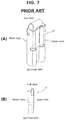
- An intermediate terminal 3 formerly proposed by the present inventors and shown in FIGS. 8(A) and 8(B) is non-directional, i.e. has the same structure at its top and bottom and at its front and back, respectively (Japanese Unexamined Utility Model Publication No. 5-79889).
- the intermediate terminal 3 shown in FIGS. 8(A) and 8(B) has generally the shape of a rectangular column.
- pairs of arcuate connecting spring portions 3b, 3b and 3c, 3c project inwardly from its front and rear surfaces 3a, 3a, forming a clearance between each pair so that the tabs 1a or 2a can be inserted at will from top or bottom.
- the tab 1a of the fuse 1 is inserted into the clearance between the connecting spring portions 3b and 3b at the top end of the intermediate terminal 3
- the tab 2a of the busbar or like device is inserted into the clearance between the connecting spring portions 3c and 3c at the bottom end thereof.
- the intermediate terminal 3 cannot be used unless the tab 1a of the fuse 1 and the tab 2a of the busbar or like device extend in the same direction as shown in FIG. 6(A).
- the invention is developed to solve the above problems, and an object thereof is to provide a more versatile intermediate terminal.
- the tab (which could be seen as a rotationally directional connection terminal) which is typically a tab with a rectangular cross section can be inserted in at least one end portion in at least two different rotational orientations. Accordingly, if the tabs (connection terminals) to be inserted into the other end portions are aligned in one rotational direction, the connection terminals to be inserted into the one end portion need not be aligned. Conclusively, the inventive intermediate terminals can be used for this type of connection without being turned about their longitudinal axes.
- two receiving portions for receiving connection terminals at a different rotational orientation are formed. If both end portions are provided with two receiving portions, the above type of connection can be made even without aligning the intermediate terminals with respect to their up/down orientation.
- the two receiving portions intersect at a right angle.
- the column has a generally rectangular cross section, and the connecting spring portions are provided at each side of the column.
- the connecting spring portions have an arcuate cross section and define two receiving portions. It is particularly preferred that the connecting spring portions are formed throughout the entire longitudinal extension of the column. Namely, the intermediate terminal is now particularly easy to manufacture, e.g. by bending and folding a plate.
- the column has a cross-like cross section defining four wings, wherein each two opposing wings define a receiving portion and wherein the connecting spring portions are formed at the sides of the wings.
- the intermediate terminal is easy to manufacture if the column is entirely hollow, particularly if also the connecting spring portions are formed over the entire length.
- the intermediate terminal is easy to handle, particularly by an automatic connecting apparatus.
- the intermediate terminals can be mounted in the electrical connection box in the same direction independently of inserting directions of tabs. Further, even if a tab of a fuse or like device and a tab of a busbar or like device extend in different directions, i.e., their extending directions are displaced by 90°, the respective tabs can be inserted into the intermediate terminal.
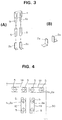
- a intermediate terminal 5 as a first embodiment has the form of a substantially square column of a conductive material (e.g. metal) as indicated by phantom line in FIGS. 1 and 2.
- a conductive material e.g. metal
- the intermediate terminal 5 is formed into the substantially square column by folding a metal plate having a width W corresponding to a height of the intermediate terminal 5 four times by generally the same length L at an angle of 90°, placing a finishing end 5b over the outer surface of a starting end 5a, and connecting the ends 5a and 5b.
- clearances g for permitting insertion of a tab 1a of a fuse 1 or a tab 2a of a busbar or like device are formed between the inner surfaces of the connecting spring portions 5g and 5h, 5h and 5i, 5i and 5j, 5j and 5g and are, thus, positioned at four corners defined by the surfaces 5c and 5d, 5d and 5e, 5e and 5f, 5f and 5c, respectively.
- first and second tab receiving portions 10 and 20 which extend through and intersect at a longitudinal axis A at a right angle.
- the inner surfaces of the connecting spring portions 5g and 5h at one diagonal end of the square terminal 5 and 5i and 5j at the opposite diagonal end are respectively opposed to each other with the first tab receiving portion 10 therebetween.
- the inner surfaces of the connecting spring portions 5g and 5j at one diagonal end of the square terminal 5 and 5h and 5i at the opposite diagonal end are opposed to each other with the second tab receiving portion 20 therebetween.
- first and second tab receiving portions 10 and 20 extend along lines L1 and L2, respectively.
- the intermediate terminals 5 can be mounted in the same direction in one electrical connection box 30 as shown in FIG. 3(A), independently of whether the tabs 2a of each busbar mounted in the electrical connection box 30 extend along the longitudinal or lateral direction orthogonally thereto and are inserted into a lower part of either the first or second tab receiving portion 10 or 20.
- the tabs 1a of relays 1A, 1B and 1C to be connected with the intermediate terminals 5 thus connected with the tabs 2a of the busbars mounted in the electrical connection box 30 can be inserted into upper parts of the first or second tab receiving portions 10 or 20 independently of whether the tabs 1a extend along the longitudinal or lateral direction.
- the tabs can be connected by means of the intermediate terminals 5 mounted in the same direction in the electrical connection box 30 both when the tabs 1a, 1a of the fuses 1 and the tabs 2a, 2a of the busbars 2 to be inserted into the first or second tab receiving portions 10 or 20 extend in the same direction as shown in FIG. 3(A) and as in fuses 1A, 1A of FIG. 4, and when the tabs 1a, 1a of the fuses 1 and the tabs 2a, 2a of the busbars 2 extend in different directions as shown in FIG. 3(B) and as in fuses 1B, 1C of FIG. 4.
- the tabs 1a, 1a of the fuse 1 extend in the same direction as the tabs 2a, 2a of the busbars as with the fuse 1A of FIG. 4, but the fuse 1 is mounted in the different direction (rotated by 90°) as the fuse 1C of FIG. 4, if the intermediate terminals 5, 5 are mounted from above regardless of the direction thereof such that the tabs 2a, 2a are inserted into the lower parts thereof, the tabs 2a, 2a are tightly held between the connecting spring portions 5g and 5h, 5i and 5j (or 5g and 5j, 5h and 5i) as shown in FIG. 2.
- the tabs 1a, 1a and 2a, 2a can be inserted into the intermediate terminals 5, 5 even if the tabs 1a, 1a of the fuse 1 extend in the direction displaced by e.g. 90° from the tabs 2a, 2a of the busbars. Accordingly, even if the fuses 1 are mounted in different directions (rotated by 90°) in the electrical connection box, the intermediate terminals 5, 5 need not be aligned in conformity with the mounting directions of the fuses 1. Thus, the automatic intermediate terminal inserting apparatus is allowed to have a simple construction, thereby reducing a production cost.
- the tabs 1a, 1a of the fuse 1 and the tabs 2a, 2a of the busbar may even be inserted into clearances between apexes of the facing arcuate connecting spring portions 5g and 5i, 5h and 5j as indicated by dashed line in FIG. 2.
- the tabs must have a specified width. To the contrary, if the tabs are inserted into the tab receiving portions, they must not have a specified width, but a specified thickness.
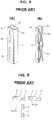
- FIG. 5 shows an intermediate terminal 3A as a second embodiment which employs the basic construction of the prior art intermediate terminal 3 shown in FIG. 8.
- the intermediate terminal 3A looks as if it were formed by cutting away one side surface 3d shown in FIG. 8(A) from the intermediate terminal 3, and joining four such intermediate terminals 3 to have a cross-like cross section by bringing the cut edges into abutment.
- the intermediate terminal 3a is formed by bending and embossing a metal plate similar to the intermediate terminal 5.
- the intermediate terminal 3A is in the form of a cross-like column. Surfaces 3e to 3h face each other.
- the intermediate terminal 3A as the second embodiment, there are also formed two tab receiving portions, namely a first tab receiving portion 10' and a second tab receiving portion 20' which intersect at right angles. Accordingly, if the intermediate terminals 3A are mounted in the same direction in the electrical connection box, the tabs of the busbars can be connected with the corresponding tabs of the relays by means of the intermediate terminals independently of whether the tabs extend in the longitudinal or lateral direction.
- the connecting spring portions are formed on the side surfaces of the rectangular column which surfaces are point-symmetrical with respect to a middle point of two intersecting directions. Accordingly, even if a tab of a fuse or like device and a tab of a busbar or like device extend in different directions, i.e., their extending directions are displaced by e.g. 90°, the respective tabs can be inserted into the same intermediate terminal. Therefore, even if fuses or like devices are mounted in different directions in the electrical connection box (rotated by 90°), the intermediate terminals need not be aligned in accordance with the mounting direction of the fuses. This makes the construction of an automatic intermediate terminal inserting apparatus simple, thereby reducing a production cost.
Landscapes
- Connection Or Junction Boxes (AREA)
Applications Claiming Priority (2)
| Application Number | Priority Date | Filing Date | Title |
|---|---|---|---|
| JP6262725A JP2814933B2 (ja) | 1994-10-26 | 1994-10-26 | 電気接続箱用の中継端子 |
| JP262725/94 | 1994-10-26 |
Publications (2)
| Publication Number | Publication Date |
|---|---|
| EP0709923A1 true EP0709923A1 (fr) | 1996-05-01 |
| EP0709923B1 EP0709923B1 (fr) | 1998-09-30 |
Family
ID=17379731
Family Applications (1)
| Application Number | Title | Priority Date | Filing Date |
|---|---|---|---|
| EP95111348A Expired - Lifetime EP0709923B1 (fr) | 1994-10-26 | 1995-07-19 | Terminal intermédiaire pour une boíte de raccordement |
Country Status (4)
| Country | Link |
|---|---|
| US (1) | US5603626A (fr) |
| EP (1) | EP0709923B1 (fr) |
| JP (1) | JP2814933B2 (fr) |
| DE (1) | DE69505086T2 (fr) |
Cited By (4)
| Publication number | Priority date | Publication date | Assignee | Title |
|---|---|---|---|---|
| DE19713960A1 (de) * | 1997-04-04 | 1998-10-08 | Whitaker Corp | Elektrische Anschlußklemme |
| US6000974A (en) * | 1994-05-10 | 1999-12-14 | The Whitaker Corporation | Universal contact receptacle |
| DE10019241A1 (de) * | 2000-04-18 | 2001-10-25 | Grote & Hartmann | Elektrisches Kontaktelement |
| WO2019229568A1 (fr) * | 2018-05-29 | 2019-12-05 | Te Connectivity Corporation | Borne de prise pour boîte de jonction |
Families Citing this family (20)
| Publication number | Priority date | Publication date | Assignee | Title |
|---|---|---|---|---|
| JP2005129389A (ja) * | 2003-10-24 | 2005-05-19 | Yazaki Corp | 中継端子 |
| DE102005043601B4 (de) * | 2005-09-12 | 2007-06-14 | Yazaki Europe Ltd., Hemel Hempstead | Kontakthalteklammer zur Montage an einer Stromschiene und Kontakthalterung aus diesen |
| US7988506B2 (en) | 2006-10-12 | 2011-08-02 | Borgwarner, Inc. | Dual female terminal with two contact portions each having an aperture and a male terminal disposed in apertures of both contact portions |
| DE102006062022B4 (de) | 2006-12-29 | 2022-05-25 | Te Connectivity Germany Gmbh | Elektrischer Kreuzkontakt |
| US9833098B2 (en) | 2009-07-14 | 2017-12-05 | Loominocity, Inc. | Architecture for routing multi-channel commands via a tree column |
| US11013356B2 (en) | 2009-07-14 | 2021-05-25 | Belgravia Wood Limited | Power pole for artificial tree apparatus with axial electrical connectors |
| US10993572B2 (en) | 2009-07-14 | 2021-05-04 | Belgravia Wood Limited | Power pole for artificial tree apparatus with axial electrical connectors |
| US8863416B2 (en) | 2011-10-28 | 2014-10-21 | Polygroup Macau Limited (Bvi) | Powered tree construction |
| CN102568885A (zh) * | 2012-02-14 | 2012-07-11 | 江门市创艺电器有限公司 | 一种新型软线开关 |
| CN102931510B (zh) * | 2012-11-08 | 2015-08-05 | 邢国坚 | 插孔接触件及其制造方法 |
| JP2016096021A (ja) * | 2014-11-14 | 2016-05-26 | 住友電装株式会社 | 基板端子付プリント基板およびそれを用いた電気接続箱 |
| US9839315B2 (en) | 2015-03-27 | 2017-12-12 | Polygroup Macau Limited (Bvi) | Multi-wire quick assemble tree |
| CN105490108A (zh) * | 2015-12-29 | 2016-04-13 | 苏州卓德电子有限公司 | 一种线束连接器用线束中部固定装置 |
| US9907136B2 (en) | 2016-03-04 | 2018-02-27 | Polygroup Macau Limited (Bv) | Variable multi-color LED light string and controller for an artificial tree |
| CN107317124A (zh) * | 2016-04-26 | 2017-11-03 | 苏州艾希迪连接器科技有限公司 | 电连接装置 |
| DE102016209478A1 (de) * | 2016-05-31 | 2017-11-30 | Te Connectivity Germany Gmbh | Verbindungskäfig zur Verbindung zweier elektrischer Flachkontakte |
| JP2019185885A (ja) * | 2018-04-03 | 2019-10-24 | 矢崎総業株式会社 | 中継端子及び中継コネクタ |
| US10181667B1 (en) * | 2018-05-29 | 2019-01-15 | Te Connectivity Corporation | Receptacle terminal for a junction box |
| JP7302382B2 (ja) | 2019-08-26 | 2023-07-04 | 株式会社オートネットワーク技術研究所 | 端子台 |
| DE102020101836A1 (de) | 2020-01-27 | 2021-07-29 | Lisa Dräxlmaier GmbH | Fixiereinrichtung für elektrische kontaktpartner |
Citations (4)
| Publication number | Priority date | Publication date | Assignee | Title |
|---|---|---|---|---|
| US2965869A (en) * | 1959-09-24 | 1960-12-20 | Ludwig Louis | Female contact for electrical outlet receptacle |
| US4460239A (en) * | 1981-03-11 | 1984-07-17 | Tokai Electric Wire Company Limited | Connector terminal |
| EP0463608A2 (fr) * | 1990-06-27 | 1992-01-02 | Yazaki Corporation | Terminal de jonction |
| JPH0579889U (ja) | 1992-03-30 | 1993-10-29 | 住友電装株式会社 | 分岐接続箱用中継端子 |
-
1994
- 1994-10-26 JP JP6262725A patent/JP2814933B2/ja not_active Expired - Fee Related
-
1995
- 1995-07-19 EP EP95111348A patent/EP0709923B1/fr not_active Expired - Lifetime
- 1995-07-19 DE DE69505086T patent/DE69505086T2/de not_active Expired - Fee Related
- 1995-08-30 US US08/520,885 patent/US5603626A/en not_active Expired - Lifetime
Patent Citations (4)
| Publication number | Priority date | Publication date | Assignee | Title |
|---|---|---|---|---|
| US2965869A (en) * | 1959-09-24 | 1960-12-20 | Ludwig Louis | Female contact for electrical outlet receptacle |
| US4460239A (en) * | 1981-03-11 | 1984-07-17 | Tokai Electric Wire Company Limited | Connector terminal |
| EP0463608A2 (fr) * | 1990-06-27 | 1992-01-02 | Yazaki Corporation | Terminal de jonction |
| JPH0579889U (ja) | 1992-03-30 | 1993-10-29 | 住友電装株式会社 | 分岐接続箱用中継端子 |
Cited By (5)
| Publication number | Priority date | Publication date | Assignee | Title |
|---|---|---|---|---|
| US6000974A (en) * | 1994-05-10 | 1999-12-14 | The Whitaker Corporation | Universal contact receptacle |
| DE19713960A1 (de) * | 1997-04-04 | 1998-10-08 | Whitaker Corp | Elektrische Anschlußklemme |
| DE19713960B4 (de) * | 1997-04-04 | 2008-01-24 | The Whitaker Corp., Wilmington | Elektrische Anschlußklemme |
| DE10019241A1 (de) * | 2000-04-18 | 2001-10-25 | Grote & Hartmann | Elektrisches Kontaktelement |
| WO2019229568A1 (fr) * | 2018-05-29 | 2019-12-05 | Te Connectivity Corporation | Borne de prise pour boîte de jonction |
Also Published As
| Publication number | Publication date |
|---|---|
| DE69505086T2 (de) | 1999-06-24 |
| JP2814933B2 (ja) | 1998-10-27 |
| US5603626A (en) | 1997-02-18 |
| EP0709923B1 (fr) | 1998-09-30 |
| DE69505086D1 (de) | 1998-11-05 |
| JPH08124639A (ja) | 1996-05-17 |
Similar Documents
| Publication | Publication Date | Title |
|---|---|---|
| EP0709923B1 (fr) | Terminal intermédiaire pour une boíte de raccordement | |
| US5554040A (en) | Joint terminal for bus bar | |
| US4460239A (en) | Connector terminal | |
| US4992062A (en) | Electrical connection device | |
| JPH08185921A (ja) | 電気接続箱 | |
| US5411419A (en) | Multipole connection terminal and method for producing same | |
| JP2001016745A (ja) | バスバーの接続構造 | |
| US5417589A (en) | Linked electrical connectors | |
| US5380218A (en) | Pressure-contact terminal structure | |
| EP0720256B1 (fr) | Boíte de raccordement électrique et borne de liaison utilisée avec une telle boíte | |
| EP1148531A2 (fr) | Fusible | |
| US5669778A (en) | IDC branch connector for large range of wire sizes | |
| US5823834A (en) | Flat plug | |
| US6224433B1 (en) | Electrical connector for crossing reinforcing bars | |
| US6179628B1 (en) | Electric connection box | |
| CA1082272A (fr) | Connecteur souple a extremite boulonnee pour disjoncteur | |
| JP2001035556A (ja) | 接続用端子、該接続用端子を用いたジョイントコネクタ及び該ジョイントコネクタを備えたワイヤハーネス | |
| EP0891124A2 (fr) | Système d'interconnexion électrique tridimensionnel | |
| JP3473447B2 (ja) | 電気接続箱用中継端子及びその電気接続箱用中継端子を用いた電気接続箱 | |
| JPH06310186A (ja) | バスバーの短絡構造 | |
| JPH0141183Y2 (fr) | ||
| JP2568652Y2 (ja) | ヒューズブロック | |
| US6141871A (en) | Electrical connection box and a method for forming terminals | |
| JP3106954B2 (ja) | 電気接続箱 | |
| JP3321018B2 (ja) | リレーの取付構造 |
Legal Events
| Date | Code | Title | Description |
|---|---|---|---|
| PUAI | Public reference made under article 153(3) epc to a published international application that has entered the european phase |
Free format text: ORIGINAL CODE: 0009012 |
|
| 17P | Request for examination filed |
Effective date: 19950719 |
|
| AK | Designated contracting states |
Kind code of ref document: A1 Designated state(s): DE FR GB |
|
| 17Q | First examination report despatched |
Effective date: 19970402 |
|
| GRAG | Despatch of communication of intention to grant |
Free format text: ORIGINAL CODE: EPIDOS AGRA |
|
| GRAG | Despatch of communication of intention to grant |
Free format text: ORIGINAL CODE: EPIDOS AGRA |
|
| GRAH | Despatch of communication of intention to grant a patent |
Free format text: ORIGINAL CODE: EPIDOS IGRA |
|
| GRAH | Despatch of communication of intention to grant a patent |
Free format text: ORIGINAL CODE: EPIDOS IGRA |
|
| GRAA | (expected) grant |
Free format text: ORIGINAL CODE: 0009210 |
|
| AK | Designated contracting states |
Kind code of ref document: B1 Designated state(s): DE FR GB |
|
| REF | Corresponds to: |
Ref document number: 69505086 Country of ref document: DE Date of ref document: 19981105 |
|
| ET | Fr: translation filed | ||
| PLBE | No opposition filed within time limit |
Free format text: ORIGINAL CODE: 0009261 |
|
| STAA | Information on the status of an ep patent application or granted ep patent |
Free format text: STATUS: NO OPPOSITION FILED WITHIN TIME LIMIT |
|
| 26N | No opposition filed | ||
| PGFP | Annual fee paid to national office [announced via postgrant information from national office to epo] |
Ref country code: FR Payment date: 20010712 Year of fee payment: 7 |
|
| PGFP | Annual fee paid to national office [announced via postgrant information from national office to epo] |
Ref country code: GB Payment date: 20010718 Year of fee payment: 7 |
|
| REG | Reference to a national code |
Ref country code: GB Ref legal event code: IF02 |
|
| PG25 | Lapsed in a contracting state [announced via postgrant information from national office to epo] |
Ref country code: GB Free format text: LAPSE BECAUSE OF NON-PAYMENT OF DUE FEES Effective date: 20020719 |
|
| GBPC | Gb: european patent ceased through non-payment of renewal fee |
Effective date: 20020719 |
|
| PG25 | Lapsed in a contracting state [announced via postgrant information from national office to epo] |
Ref country code: FR Free format text: LAPSE BECAUSE OF NON-PAYMENT OF DUE FEES Effective date: 20030331 |
|
| REG | Reference to a national code |
Ref country code: FR Ref legal event code: ST |
|
| PGFP | Annual fee paid to national office [announced via postgrant information from national office to epo] |
Ref country code: DE Payment date: 20080724 Year of fee payment: 14 |
|
| PG25 | Lapsed in a contracting state [announced via postgrant information from national office to epo] |
Ref country code: DE Free format text: LAPSE BECAUSE OF NON-PAYMENT OF DUE FEES Effective date: 20100202 |