EP0709945B1 - Elektromotor mit temperaturabhängigem Bauelement - Google Patents
Elektromotor mit temperaturabhängigem Bauelement Download PDFInfo
- Publication number
- EP0709945B1 EP0709945B1 EP95810460A EP95810460A EP0709945B1 EP 0709945 B1 EP0709945 B1 EP 0709945B1 EP 95810460 A EP95810460 A EP 95810460A EP 95810460 A EP95810460 A EP 95810460A EP 0709945 B1 EP0709945 B1 EP 0709945B1
- Authority
- EP
- European Patent Office
- Prior art keywords
- stator
- temperature
- insulation
- temperature dependent
- dependent unit
- Prior art date
- Legal status (The legal status is an assumption and is not a legal conclusion. Google has not performed a legal analysis and makes no representation as to the accuracy of the status listed.)
- Expired - Lifetime
Links
- 238000004804 winding Methods 0.000 claims description 32
- 230000001419 dependent effect Effects 0.000 claims description 29
- 238000009413 insulation Methods 0.000 claims description 25
- 239000004020 conductor Substances 0.000 claims description 2
- 230000004308 accommodation Effects 0.000 claims 1
- 238000000034 method Methods 0.000 description 2
- 238000009434 installation Methods 0.000 description 1
- 239000012212 insulator Substances 0.000 description 1
- 238000004519 manufacturing process Methods 0.000 description 1
- 239000002966 varnish Substances 0.000 description 1
Images

Classifications
-
- H—ELECTRICITY
- H02—GENERATION; CONVERSION OR DISTRIBUTION OF ELECTRIC POWER
- H02K—DYNAMO-ELECTRIC MACHINES
- H02K11/00—Structural association of dynamo-electric machines with electric components or with devices for shielding, monitoring or protection
- H02K11/20—Structural association of dynamo-electric machines with electric components or with devices for shielding, monitoring or protection for measuring, monitoring, testing, protecting or switching
- H02K11/25—Devices for sensing temperature, or actuated thereby
-
- H—ELECTRICITY
- H02—GENERATION; CONVERSION OR DISTRIBUTION OF ELECTRIC POWER
- H02K—DYNAMO-ELECTRIC MACHINES
- H02K29/00—Motors or generators having non-mechanical commutating devices, e.g. discharge tubes or semiconductor devices
-
- H—ELECTRICITY
- H02—GENERATION; CONVERSION OR DISTRIBUTION OF ELECTRIC POWER
- H02K—DYNAMO-ELECTRIC MACHINES
- H02K11/00—Structural association of dynamo-electric machines with electric components or with devices for shielding, monitoring or protection
Definitions
- the invention relates to an electric motor with a stator having pronounced poles.
- Stator windings and insulation bodies for the insulation of the respective end faces of the Stator wherein the insulating body is essentially ring-shaped, arranged on the end faces of the stator base body have, of which collars project axially in the region of the poles and being on the base body Terminals are arranged.
- DE-OS 30 37 615 describes a method for determining stator windings Electric motor known.
- the end faces of a made up of a laminated core with pronounced Poles composing stator are covered with an insulation body, of its base body two substantially diametrically opposite Protrude collar.
- the collars are used for fixing of the winding heads of the stator windings formed in the area of the end faces, where the stator windings penetrate the cavities defined by the collars.
- the Insulation body essentially consists of a ring-shaped base body, which, in addition to two protruding collars, also has connection terminals. While When the electric motor is started up, it heats up. The permissible Temperatures exceeded, this can damage the winding insulation to lead.
- the Winding packages consist of a stator winding and one of the adapters Insulator body serving stator winding made of a non-current-conducting material together, penetrate the stator and protrude over both end faces of the same. At least one of the two insulation bodies has a pocket-shaped recess, in which a temperature-dependent component is accommodated. The temperature dependent The component is arranged laterally next to a stator winding and through a wall part the pocket-shaped recess is separated from the stator winding.
- the invention has for its object an economically producible electric motor to create, in which damage caused by excessive temperatures are avoided.
- the object is achieved in that at least one Collar on one of the insulation bodies, over which the stator winding temperature-dependent component is arranged with electrical wires, the Electrical wires are connected to the connection terminals.
- the temperature-dependent component Due to the arrangement of the temperature-dependent component according to the invention quick and economical installation is possible on at least one of the insulation bodies guaranteed the temperature-dependent component on the stator of the electric motor.
- the temperature-dependent component is placed on the insulation body overwound on the stator with the stator winding so that the temperature dependent Component is in direct contact with the stator winding in order to this can be heated.
- the wire of the stator winding from an insulation layer surrounded, for example, in the form of a varnish is the temperature-dependent Device in indirect contact with the stator winding. A very good temperature transfer between the temperature-dependent component and the stator winding is thus guaranteed.
- the temperature-dependent one arranged on the insulation body The component has two electrical wires, via the corresponding switch-on and switch-off signals for the current limitation.
- the basic body of the insulation body has connecting terminals on which before the insulation body is installed the electrical wires of the temperature-dependent component are attached.
- the temperature dependent The component and the insulation body thus form an assembly unit, which can be attached as a whole to the end face of the stator.
- the temperature-dependent component is expediently in one towards the collar arranged open recess of the base body.
- This recess ensures a safe, non-slip arrangement of the temperature-dependent component the base body of the insulation body.
- the recess is arranged under a collar.
- this is preferably temperature-dependent Component firmly connected to the base body.
- the temperature dependent The component is glued to the base body, plugged onto the base body or connected to the base body by means of a fastening element.
- the temperature-dependent component is preferably an indirectly heated PTC thermistor.
- the resistance value of a PTC thermistor almost increases with increasing temperature abruptly as soon as a certain temperature is exceeded.
- the PTC thermistors are also used as a PTC resistor designated.
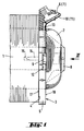
- the electric series motor partially shown in Fig. 1 has one of a Laminated core existing stator 1, on the end face 4 an insulation body 3 is plugged is.
- the connection between the insulation body 3 and the stator 1 exists from pin-shaped connecting elements 14 which on a first side 17 of the Base body 5 are arranged and in appropriately designed receiving bores 15 of the stator 1 protrude.
- the insulation body 3 is composed of an essentially ring-shaped formed base body 5, from that on a second side facing away from the stator 1 18 protrude two diametrically opposite collars 8.
- a recess 12 is arranged to accommodate a temperature-dependent component 9 serves
- An openly formed receiving channel extends from the recess 12 13 to terminals 6, 7.
- the temperature-dependent component is with electrical wires 10, 11, which are guided in the receiving channel 13, with the Terminals 6, 7 connected.
- the recess 12 is under the collar 8 in an area of the base body 5 which is wound with a stator winding 2 becomes.
- the depth of the receiving channel 13 is dimensioned such that the in the Receiving channel 13 arranged electrical wires 10, 11 over the surface of the base body 5 do not protrude in the area of the receiving channel 13, so that a contact of the electric wires 10, 11 with the stator winding 2 is prevented.
- Winding ends of the stator windings 2 can, for example, on likewise not shown, further connecting elements arranged on the base body 5 can be fastened.
- the base body 5 has through openings 16 which are diametrically opposite one another and are arranged offset from the collar 8 by 90 °.
Landscapes
- Engineering & Computer Science (AREA)
- Power Engineering (AREA)
- Microelectronics & Electronic Packaging (AREA)
- Insulation, Fastening Of Motor, Generator Windings (AREA)
Description
- Fig. 1
- einen erfindungsgemässen Isolationskörper, in Verbindung mit einem Stator und einer Statorwicklung;
- Fig. 2
- den Isolationskörper gemäss Fig. 1, in der Ansicht II, gemäss Fig. 1.
Claims (5)
- Elektromotor mit ausgeprägte Pole aufweisendem Stator (1), Statorwicklungen (2) und lsolationskörpern (3) für die Isolierung des jeweiligen Stirnflächen (4) des Stators (1), wobei die Isolationskörper (3) im wesentlichen ringförmig ausgebildete, auf den Stirnflächen (4) des Stators (1) angeordnete Grundkörper (5) aufweisen, von denen im Bereich der Pole Kragen (8) axial abragen und wobei am GrundkörperAnschlussklemmen (6, 7) angeordnet sind, dadurch gekennzeichnet, dass im Bereich wenigstens eines Kragens (8) an einem der Isolationskörper (3) ein von der Statorwicklung (2) überwickeltes, temperaturabhängiges Bauelement (9) mit Elektrodrähten (10, 11) angeordnet ist, wobei die Elektrodrähte (10, 11) mit den Anschlussklemmen (6, 7) in Verbindung stehen.
- Motor nach Anspruch 1, dadurch gekennzeichnet, dass das temperaturabhängige Bauelement (9) in einer zum Kragen (8) hin offenen Ausnehmung (12) des Grundkörpers (5) angeordnet ist.
- Motor nach Anspruch 1 oder 2, dadurch gekennzeichnet, dass das temperaturabhängige Bauelement (9) fest mit dem Grundkörper (5) verbunden ist.
- Motor nach einem der Ansprüche 1 bis 3, dadurch gekennzeichnet, dass die für die Verbindung des temperaturabhängigen Bauelementes (9) mit den Anschlussklemmen (6, 7) vorgesehenen Elektrodrähte (10, 11) in einem Aufnahmekanal (13) des Grundkörpers (5) angeordnet sind.
- Motor nach einem der Ansprüche 1 bis 4, dadurch gekennzeichnet, dass das temperaturabhängige Bauelement (9) ein indirekt beheizter Kaltleiter ist.
Applications Claiming Priority (2)
| Application Number | Priority Date | Filing Date | Title |
|---|---|---|---|
| DE4438242 | 1994-10-26 | ||
| DE4438242A DE4438242A1 (de) | 1994-10-26 | 1994-10-26 | Elektromotor mit temperaturabhängigem Bauelement |
Publications (2)
| Publication Number | Publication Date |
|---|---|
| EP0709945A1 EP0709945A1 (de) | 1996-05-01 |
| EP0709945B1 true EP0709945B1 (de) | 1999-05-12 |
Family
ID=6531741
Family Applications (1)
| Application Number | Title | Priority Date | Filing Date |
|---|---|---|---|
| EP95810460A Expired - Lifetime EP0709945B1 (de) | 1994-10-26 | 1995-07-12 | Elektromotor mit temperaturabhängigem Bauelement |
Country Status (5)
| Country | Link |
|---|---|
| EP (1) | EP0709945B1 (de) |
| JP (1) | JPH08214505A (de) |
| KR (1) | KR100318615B1 (de) |
| DE (2) | DE4438242A1 (de) |
| ES (1) | ES2132578T3 (de) |
Families Citing this family (5)
| Publication number | Priority date | Publication date | Assignee | Title |
|---|---|---|---|---|
| DE19859011C1 (de) * | 1998-12-21 | 2000-09-21 | Metabowerke Kg | Elektromotor |
| DE19925699C1 (de) * | 1999-06-04 | 2000-11-02 | Interelectric Ag Sachseln | Elektromotor oder -Generator |
| CN101233396B (zh) | 2005-03-23 | 2010-12-22 | 丰田自动车株式会社 | 温度检测器和固定材料移动抑制结构 |
| CN102812624A (zh) | 2010-03-24 | 2012-12-05 | 丰田自动车株式会社 | 使温度检测元件邻接的器具 |
| DE102013003052A1 (de) * | 2013-02-20 | 2014-09-04 | Ziehl-Abegg Se | Einrichtung mit einem eine Wicklung aufweisenden Lamellenpaket und Stator für einen Elektromotor mit einer solchen Einrichtung |
Family Cites Families (4)
| Publication number | Priority date | Publication date | Assignee | Title |
|---|---|---|---|---|
| US4028570A (en) * | 1975-06-18 | 1977-06-07 | Emerson Electric Co. | Self locking molded thermostat strap |
| DE3021689A1 (de) | 1980-06-10 | 1981-12-17 | Metabowerke GmbH & Co, 7440 Nürtingen | Ueberlastsicherung fuer den motor, insbesondere eines elektrohandwerkzeugs |
| DE3037615C2 (de) | 1980-10-04 | 1983-12-01 | Licentia Patent-Verwaltungs-Gmbh, 6000 Frankfurt | Verfahren zur Festlegung der Wickelköpfe der Feldspulen von elektrischen Maschinen mit ausgeprägten Polen |
| IT223866Z2 (it) * | 1990-01-18 | 1995-10-03 | Cartoccio per bobine di motori elettrici a corrente alternata, corredato di tasca per l'appoggio e l'arresto dell'interruttore termico salvamotore. |
-
1994
- 1994-10-26 DE DE4438242A patent/DE4438242A1/de not_active Withdrawn
-
1995
- 1995-07-12 ES ES95810460T patent/ES2132578T3/es not_active Expired - Lifetime
- 1995-07-12 DE DE59505894T patent/DE59505894D1/de not_active Expired - Lifetime
- 1995-07-12 EP EP95810460A patent/EP0709945B1/de not_active Expired - Lifetime
- 1995-09-05 KR KR1019950028906A patent/KR100318615B1/ko not_active Expired - Lifetime
- 1995-10-26 JP JP7279321A patent/JPH08214505A/ja active Pending
Also Published As
| Publication number | Publication date |
|---|---|
| ES2132578T3 (es) | 1999-08-16 |
| DE4438242A1 (de) | 1996-05-02 |
| JPH08214505A (ja) | 1996-08-20 |
| KR100318615B1 (ko) | 2002-04-22 |
| KR960016069A (ko) | 1996-05-22 |
| EP0709945A1 (de) | 1996-05-01 |
| DE59505894D1 (de) | 1999-06-17 |
Similar Documents
| Publication | Publication Date | Title |
|---|---|---|
| DE3447826C2 (de) | Elektro-Außenläufermotor | |
| DE112020005633T5 (de) | System zum radialen einsetzen eines thermistors in einen statorkern | |
| DE19609655C2 (de) | Zündvorrichtung für einen Verbrennungsmotor | |
| DE1102249B (de) | Widerstand mit Schmelzsicherung | |
| EP0709945A1 (de) | Elektromotor mit temperaturabhängigem Bauelement | |
| WO1998012713A1 (de) | Kontaktgruppe für halbleiter-widerstände, wie kaltleiter | |
| DE3382581T4 (de) | Langgestreckte elektrische Heizvorrichtung und Einrichtung mit solchen Vorrichtungen. | |
| DE102004027653B4 (de) | Elektromotor | |
| DE102016211599A1 (de) | Segmentierter Stator und Verfahren zum Verschalten des Stators | |
| EP3895291B1 (de) | Stator und elektrische maschine | |
| DE3129862A1 (de) | Widerstandsanordnung | |
| WO2021190694A1 (de) | Vorrichtung zur anbringung eines temperatursensors an eine elektrische maschine und elektrische maschine mit vorrichtung zur temperaturmessung | |
| EP0066644B1 (de) | Anordnung und Verfahren zum Verschalten der Wicklungsenden der Statorwicklung eines Kleinmotors | |
| DE102004057750B4 (de) | Verfahren zur Herstellung eines Kommutators sowie Kommutator | |
| DE19859011C1 (de) | Elektromotor | |
| DE3102849A1 (de) | "anordnung zur innenpotentialsteuerung bei verdrillten generatorstaeben" | |
| EP0843325B1 (de) | Kleintransformator | |
| DE8026597U1 (de) | In eine der beiden zur isolierung der stirnflaechen des staenderblechpakets elektrischer maschinen mit ausgepraegten polen dienenden endscheiben eingesetzte anschlussklemmen | |
| CH673917A5 (de) | ||
| DE69808692T2 (de) | Elektrischer Widerstand als widerstandsfähiger flexibler Gürtel und mit diesem Widerstand versehenes Gerät | |
| DE69502016T2 (de) | Zusammenbau eines scheibenförmigen Varistors und Montageverfahren eines scheibenförmigen Varistors | |
| EP1665501A1 (de) | Elektromotor | |
| EP1503483B1 (de) | Verfahren zum Befestigen einer Entstördrossel sowie Vorrichtung beinhaltend eine solche Entstördrossel | |
| EP1480290B1 (de) | Kontaktanordnung mit einer Drahtverbindung | |
| DE3312513A1 (de) | Transformator |
Legal Events
| Date | Code | Title | Description |
|---|---|---|---|
| PUAI | Public reference made under article 153(3) epc to a published international application that has entered the european phase |
Free format text: ORIGINAL CODE: 0009012 |
|
| AK | Designated contracting states |
Kind code of ref document: A1 Designated state(s): BE CH DE ES FR GB IT LI NL SE |
|
| 17P | Request for examination filed |
Effective date: 19960524 |
|
| 17Q | First examination report despatched |
Effective date: 19970910 |
|
| GRAG | Despatch of communication of intention to grant |
Free format text: ORIGINAL CODE: EPIDOS AGRA |
|
| GRAG | Despatch of communication of intention to grant |
Free format text: ORIGINAL CODE: EPIDOS AGRA |
|
| GRAH | Despatch of communication of intention to grant a patent |
Free format text: ORIGINAL CODE: EPIDOS IGRA |
|
| GRAH | Despatch of communication of intention to grant a patent |
Free format text: ORIGINAL CODE: EPIDOS IGRA |
|
| GRAA | (expected) grant |
Free format text: ORIGINAL CODE: 0009210 |
|
| ITF | It: translation for a ep patent filed | ||
| AK | Designated contracting states |
Kind code of ref document: B1 Designated state(s): BE CH DE ES FR GB IT LI NL SE |
|
| PG25 | Lapsed in a contracting state [announced via postgrant information from national office to epo] |
Ref country code: NL Free format text: LAPSE BECAUSE OF FAILURE TO SUBMIT A TRANSLATION OF THE DESCRIPTION OR TO PAY THE FEE WITHIN THE PRESCRIBED TIME-LIMIT Effective date: 19990512 |
|
| REG | Reference to a national code |
Ref country code: CH Ref legal event code: EP |
|
| REF | Corresponds to: |
Ref document number: 59505894 Country of ref document: DE Date of ref document: 19990617 |
|
| REG | Reference to a national code |
Ref country code: ES Ref legal event code: FG2A Ref document number: 2132578 Country of ref document: ES Kind code of ref document: T3 |
|
| GBT | Gb: translation of ep patent filed (gb section 77(6)(a)/1977) |
Effective date: 19990726 |
|
| ET | Fr: translation filed | ||
| PLBE | No opposition filed within time limit |
Free format text: ORIGINAL CODE: 0009261 |
|
| STAA | Information on the status of an ep patent application or granted ep patent |
Free format text: STATUS: NO OPPOSITION FILED WITHIN TIME LIMIT |
|
| 26N | No opposition filed | ||
| PGFP | Annual fee paid to national office [announced via postgrant information from national office to epo] |
Ref country code: ES Payment date: 20000719 Year of fee payment: 6 |
|
| PG25 | Lapsed in a contracting state [announced via postgrant information from national office to epo] |
Ref country code: ES Free format text: LAPSE BECAUSE OF NON-PAYMENT OF DUE FEES Effective date: 20010713 |
|
| REG | Reference to a national code |
Ref country code: GB Ref legal event code: IF02 |
|
| REG | Reference to a national code |
Ref country code: ES Ref legal event code: FD2A Effective date: 20020810 |
|
| PG25 | Lapsed in a contracting state [announced via postgrant information from national office to epo] |
Ref country code: IT Free format text: LAPSE BECAUSE OF NON-PAYMENT OF DUE FEES;WARNING: LAPSES OF ITALIAN PATENTS WITH EFFECTIVE DATE BEFORE 2007 MAY HAVE OCCURRED AT ANY TIME BEFORE 2007. THE CORRECT EFFECTIVE DATE MAY BE DIFFERENT FROM THE ONE RECORDED. Effective date: 20050712 |
|
| PGFP | Annual fee paid to national office [announced via postgrant information from national office to epo] |
Ref country code: CH Payment date: 20140714 Year of fee payment: 20 Ref country code: DE Payment date: 20140709 Year of fee payment: 20 |
|
| PGFP | Annual fee paid to national office [announced via postgrant information from national office to epo] |
Ref country code: FR Payment date: 20140708 Year of fee payment: 20 Ref country code: SE Payment date: 20140711 Year of fee payment: 20 Ref country code: GB Payment date: 20140709 Year of fee payment: 20 |
|
| PGFP | Annual fee paid to national office [announced via postgrant information from national office to epo] |
Ref country code: BE Payment date: 20140714 Year of fee payment: 20 |
|
| REG | Reference to a national code |
Ref country code: DE Ref legal event code: R071 Ref document number: 59505894 Country of ref document: DE |
|
| REG | Reference to a national code |
Ref country code: CH Ref legal event code: PL |
|
| REG | Reference to a national code |
Ref country code: GB Ref legal event code: PE20 Expiry date: 20150711 |
|
| REG | Reference to a national code |
Ref country code: SE Ref legal event code: EUG |
|
| PG25 | Lapsed in a contracting state [announced via postgrant information from national office to epo] |
Ref country code: GB Free format text: LAPSE BECAUSE OF EXPIRATION OF PROTECTION Effective date: 20150711 |