EP0709951A2 - Motorregelsystem - Google Patents
Motorregelsystem Download PDFInfo
- Publication number
- EP0709951A2 EP0709951A2 EP95120463A EP95120463A EP0709951A2 EP 0709951 A2 EP0709951 A2 EP 0709951A2 EP 95120463 A EP95120463 A EP 95120463A EP 95120463 A EP95120463 A EP 95120463A EP 0709951 A2 EP0709951 A2 EP 0709951A2
- Authority
- EP
- European Patent Office
- Prior art keywords
- phase
- data
- speed
- signal
- motor
- Prior art date
- Legal status (The legal status is an assumption and is not a legal conclusion. Google has not performed a legal analysis and makes no representation as to the accuracy of the status listed.)
- Granted
Links
Images


Classifications
-
- H—ELECTRICITY
- H02—GENERATION; CONVERSION OR DISTRIBUTION OF ELECTRIC POWER
- H02P—CONTROL OR REGULATION OF ELECTRIC MOTORS, ELECTRIC GENERATORS OR DYNAMO-ELECTRIC CONVERTERS; CONTROLLING TRANSFORMERS, REACTORS OR CHOKE COILS
- H02P23/00—Arrangements or methods for the control of AC motors characterised by a control method other than vector control
- H02P23/18—Controlling the angular speed together with angular position or phase
- H02P23/186—Controlling the angular speed together with angular position or phase of one shaft by controlling the prime mover
Definitions
- the present invention relates to a motor control system. More specifically, the present invention relates to a motor control system which is utilized for controlling a drum motor and a capstan motor of a VTR, for example.
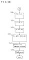
- speed error data is outputted by a speed detection portion 3 on the basis of a speed signal (FG signal) from a motor 2
- phase error data is outputted by a phase detection portion 4 on the basis of a phase signal (PG signal) from the motor 2 and a vertical synchronization signal (Vsync).
- the speed error data and the phase error data are synthesized with each other, and a synthesized result is inputted to a driver 6 via a filter 5, such that the motor 2 is driven by the driver 6.
- the speed error data is outputted by the speed detection portion 3 on the basis of the FG signal
- speed integration data is outputted by a speed integration portion 7 by sequentially adding differences between the speed error data and a theoretical FG period data that is applied from an outside.
- the speed integration data is synthesized with the speed error data, and a synthesized result is given to the driver 6 through the filter 5.
- the above described theoretical FG period data and phase difference data between the PG signal that is applied via a switch 8 and the vertical synchronization signal Vsync are synthesized with each other, whereby the phase lock between the vertical synchronization signal Vsync and the PG signal can be established by changing the theoretical FG period data.
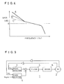
- a sufficient pull-in range for the phase In the conventional motor control system 1 shown in Figure 9, it is impossible to secure a sufficient pull-in range for the phase. In contrast, in the motor control system 1' shown in Figure 10, the pull-in range can be made broader enough because an integration type phase servo-control is performed; however, in the both prior arts, there was a problem that a sufficient gain can not be secured in a case of a miniaturized motor which is utilized in an 8 mm VTR, for example, as shown by a line B in Figure 4. In addition, a line C in Figure 4 is representative of a transfer function of a case where only a speed servo-control is performed.
- a principal object of the present invention is to provide a motor control system in which it is possible to make a pull-in range for a phase broader and a servo-gain larger.
- a motor control system controls a motor outputting a speed signal and a phase signal, comprising: speed detecting means for outputting a speed error signal component on the basis of said speed signal; phase detecting means for outputting a phase error signal component on the basis of said phase signal; synthesizing means for synthesizing said speed error signal component and said phase error signal component with each other; acceleration detecting means for detecting acceleration of the rotation of said motor; and filter means for filtering an output of said synthesizing means with different synthesizing ratios of filter outputs of different degrees in response to said accelration.
- a synthesizing ratio of different degrees of the filter means, a primary filter output and a secondary filter output is continuously changed according to the acceleration. Therefore, the larger acceleration, the larger ratio of the primary filter output. Accordingly, in a transient state, a transient response becomes stable because the ratio of the primary filter output becomes larger, and in a normal state, a gain of a low-frequency region becomes larger because the ratio of the secondary filter output is made larger.
- a motor control system 10 of this embodiment shown is a so-called software servo-control system for a drum motor 12.
- a PG signal and an FG signal are outputted from the drum motor 12, and then, inputted to a microcomputer 16 via amplifiers 14a and 14b.
- theoretical FG period data T that is an ideal value of an FG period
- a vertical synchronization signal Vsync and theoretical phase error data T ⁇ that is an ideal value of a phase difference between the vertical synchronisation signal Vsync and the PG signal are inputted to the microcomputer 16.
- the microcomputer 16 executes a so-called software servo-control on the basis of these signals and data so as to apply a driving signal to a driver 18.
- FG period data (R3) is calculated.
- FRC free-running counter
- the speed error data (R4) is set as "2 m - 1" in a step S5.
- "m” denotes an arbitrary integer.
- the present FG capture data (R1) is set as the last FG capture data (R2).
- a difference between the FG period data (R3) and the theoretical FG period data (T) is calculated by an accumulator (not shown), and a result thereof is held by the accumulator (A).
- a held value (A) and speed integration data (R5) are sequentially added to each other, whereby succeeding speed integration data (R5) can be calculated.
- a difference between PG timer data (R6) and Vsync timer data (R7) is calculated by an accumulator (not shown), and a result thereof is held in the accumulator (A).
- the PG timer data (R6) and the Vsync timer data (R7) are data of the FRC 20 at a timing that the PG signal is inputted and data of the FRC 20 at a timing that the vertical synchronization signal Vsync is inputted, respectively.
- a difference between the value (A) of accumulator and the theoretical phase data T ⁇ is evaluated, and the difference is held in an accumulator (8).
- sequential phase integration data (R8) can be evaluated by sequentially adding the value (A) to the phase integration data (R8) in a step S23.
- a motor control signal obtained through the D/A conversion is outputted from the microcomputer 16, and the same is applied to the driver 18, and accordingly, the drum motor 12 is driven by a motor driving voltage from the driver 18.
- the speed error data (R4) and the speed integration data (R5) are synthesized with each other in the step S25, the phase servo-control for suppressing a so-called drift is executed.
- the phase servo-control is an integration type phase servo-control, and therefore, it is possible to obtain a pull-in range broader enough.
- the degree of the phase integration data (R8) becomes higher than the degree of the speed integration data (R5) by one degree, and therefore, by synthesizing the phase integration data (R8) with the above described data in the step S25, the servo-gain for the phase becomes high as shown by a line A in Figure 4. Therefore, the phase of the drum motor 12 is locked, and thus, a locked point is not changed at a winding start and a winding end of a video tape, and there occurs no change of a lock point according to a rotation period of a reel base.
- Figure 5 embodiment is an embodiment capable of solving another problem in the prior art. More specifically, in the conventional motor control system, since a synthesizing ratio of the speed and the phase is constant, the pull-in time in a transient state becomes long when the ratio of the speed is larger than the ratio of the phase, and when the ratio of the phase is larger than the ratio of the speed, a stability of the rotation of the motor becomes bad. Furthermore, if the degree of the filter (lag filter) is made constant, the rotation of the motor becomes unstable in the transient state or in a normal state. Even when the degree of the lag filter is changed in the transient state or the normal state, an output signal of the lag filter is suddenly changed at a timing that the degree is changed, the rotation of the motor also becomes unstable.
- lag filter lag filter
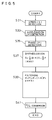
- Figure 5 embodiment is able to solve such the problems. More specifically, in a first step S31, a rotation speed (S) of the motor 12 is detected on the basis of the FG signal. Next, in a step S33, a period of the FG signal between the last inputted FG signal and the present inputted FG signal is detected, and an acceleration (K) of the rotation of the motor 12 is evaluated on the basis of the FG signal period. Furthermore, in a step S35, a rotation phase (P) of the motor 12 is detected on the basis of the PG signal.
- the rotation speed (S), the acceleration (K) and the phase (P) are substituted in the following equation (1) in a step S7, and therefore, the rotation speed (S) and the rotation phase (P) are synthesized with each other according to the synthesizing ratio that is determined by the acceleration (K).
- a maximum value of the acceleration (K) is set as "7” and a minimum value of the same is set as "1" (1 ⁇ K ⁇ 7).
- G (8 - K)S/8 + KP/8
- the synthesized data (G) is succeedingly subjected to a filtering process in a step S39.
- a primary lag filter output (F1) and a secondary lag filter output (F2) can be obtained on the basis of the synthesized data (G), and the same are substituted in the following equation (2). Therefore, the primary lag filter output (F1) and the secondary lag filter output (F2) are synthesized with each other according to a synthesizing ratio that is determined by a value K' (0 ⁇ K' ⁇ 1) that is obtained through normalization of the acceleration (K).
- A F1 x K' + (1 - K') x F2
- the synthesized data (A) is converted into a motor control signal in a step S11 to be outputted from the microcomputer 16. Then, the motor 12 is driven by the driver 18 in accordance with the motor control signal.
- G S/8 + 7P/8 (4)
- G 7S/8 + P/8 That is, the larger acceleration, the larger ratio of the phase. Therefore, in the transient state where the acceleration is large, the ratio of the phase becomes large, and therefore, the pull-in time becomes short. Furthermore, the smaller acceleration, the larger ratio of the speed. Therefore, in the normal state where the acceleration is small, the unevenness of the rotation of the motor becomes small, and therefore, the motor is rotated stably.
- the ratio of the primary lag filter output (F1) becomes large at a state where the acceleration (K') is large (transient state), and the ratio of the secondary lag filter output (F2) becomes large at a state where the acceleration (K') is small (normal state).
- Figure 6 shows a transient response characteristic of the number of rotations of the motor, and as seen from Figure 6, the transient response is stable when the ratio of the primary lag filter output is large, and the transient response becomes unstable when the ratio of the secondary lag filter output is large.
- Figure 7 shows a frequency characteristic of the servo-gain, and as seen from Figure 7, the servo-gain in a low frequency region is small when the ratio of the primary lag filter output is larger, but the servo-gain in the low frequency region becomes large as the ratio of the secondary lag filter output becomes larger. Then, in this embodiment shown in Figure 5, since the ratio of the primary lag filter output band the secondary lag filter output is continuously changed in response to a change of the acceleration, no phenomenon that the rotation of the motor 12 becomes unstable due to occurring of discontinuous points.
- a first embodiment shown by Figure 3A and Figure 3B and second embodiment shown by Figure 5 are combined with each other. More specifically, a software servo-control routine shown in Figure 8A and Figure 8B is an interrupt routine that is executed at every timing of the FG signal from the drum motor 12, as similar to the first embodiment or the second embodiment.
- steps S101 - S113 shown in Figure 8A are executed for detecting the speed (R4: S) as similar to the steps S1 - S13 of the first embodiment. However, since the steps S101 - S113 are similar to the steps S1 - S13 of the first embodiment, a duplicate description will be omitted here.
- the acceleration (K) is detected through a method similar to that of the step S33 of the second embodiment.
- steps S115 - S123 shown in Figure 8A and Figure 8B an operation for detecting the phase is executed. More specifically, in the steps S115 - S123, the phase (R5: P) is detected as similar to the steps S15 - S23 of the first embodiment. However, since the steps S115 - S123 are similar to the steps S15 - S23, a duplicate description will be omitted here.
- step S125 shown in Figure 8B that is the same as the step S25 of the first embodiment, the speed error data and the phase error data are synthesized according to the synthesizing ratios a and b to obtain the synthesized result (R9). Then, in a step S127', the synthesized result (R9) is subjected to the filtering process. More specifically, as similar to the step S127 of the second embodiment, the primary filter output (F1) and the secondary filter output (F2) are synthesized with each other in response to the acceleration (K) evaluated in the previous step S114.
- the present invention is described in connection to a servo-control system of the drum motor 12; however, it is needless to say that the present invention can be applied an arbitrary motor control system in which the phase control is required.
- the present invention can be applied to not only the software servo-control system utilizing the microcomputer but also a motor control system constructed by a hardware.
Landscapes
- Engineering & Computer Science (AREA)
- Power Engineering (AREA)
- Control Of Electric Motors In General (AREA)
Applications Claiming Priority (5)
| Application Number | Priority Date | Filing Date | Title |
|---|---|---|---|
| JP262235/92 | 1992-09-30 | ||
| JP4262235A JP3005369B2 (ja) | 1992-09-30 | 1992-09-30 | サーボシステム |
| JP4292733A JPH06153563A (ja) | 1992-10-30 | 1992-10-30 | サーボシステム |
| JP292733/92 | 1992-10-30 | ||
| EP93115755A EP0590653B1 (de) | 1992-09-30 | 1993-09-29 | Motorregelsystem |
Related Parent Applications (2)
| Application Number | Title | Priority Date | Filing Date |
|---|---|---|---|
| EP93115755.6 Division | 1993-09-29 | ||
| EP93115755A Division EP0590653B1 (de) | 1992-09-30 | 1993-09-29 | Motorregelsystem |
Publications (3)
| Publication Number | Publication Date |
|---|---|
| EP0709951A2 true EP0709951A2 (de) | 1996-05-01 |
| EP0709951A3 EP0709951A3 (de) | 1996-08-07 |
| EP0709951B1 EP0709951B1 (de) | 1998-12-02 |
Family
ID=26545459
Family Applications (2)
| Application Number | Title | Priority Date | Filing Date |
|---|---|---|---|
| EP93115755A Expired - Lifetime EP0590653B1 (de) | 1992-09-30 | 1993-09-29 | Motorregelsystem |
| EP95120463A Expired - Lifetime EP0709951B1 (de) | 1992-09-30 | 1993-09-29 | Motorregelsystem |
Family Applications Before (1)
| Application Number | Title | Priority Date | Filing Date |
|---|---|---|---|
| EP93115755A Expired - Lifetime EP0590653B1 (de) | 1992-09-30 | 1993-09-29 | Motorregelsystem |
Country Status (3)
| Country | Link |
|---|---|
| US (1) | US5420960A (de) |
| EP (2) | EP0590653B1 (de) |
| DE (2) | DE69322414T2 (de) |
Families Citing this family (3)
| Publication number | Priority date | Publication date | Assignee | Title |
|---|---|---|---|---|
| JP3262926B2 (ja) * | 1993-12-08 | 2002-03-04 | ローム株式会社 | 回転体の回転制御回路 |
| JP3229752B2 (ja) * | 1994-06-23 | 2001-11-19 | 三洋電機株式会社 | モータサーボシステム |
| US6121747A (en) * | 1997-09-02 | 2000-09-19 | Servologic Ltd. | Electric motor controller |
Family Cites Families (3)
| Publication number | Priority date | Publication date | Assignee | Title |
|---|---|---|---|---|
| US4804894A (en) * | 1986-06-10 | 1989-02-14 | Sony Corporation | Motor rotation servo control apparatus |
| US4885793A (en) * | 1987-02-10 | 1989-12-05 | Sanyo Electric Co., Ltd. | Digital servo system using microcomputer for controlling phase and speed of rotary body |
| US5019958A (en) * | 1990-02-12 | 1991-05-28 | Varga Ljubomir D | Generalized synthesis of control systems of zero-order/instantaneous response and infinite disturbance rejection ratio |
-
1993
- 1993-09-28 US US08/127,552 patent/US5420960A/en not_active Expired - Lifetime
- 1993-09-29 EP EP93115755A patent/EP0590653B1/de not_active Expired - Lifetime
- 1993-09-29 EP EP95120463A patent/EP0709951B1/de not_active Expired - Lifetime
- 1993-09-29 DE DE69322414T patent/DE69322414T2/de not_active Expired - Fee Related
- 1993-09-29 DE DE69317193T patent/DE69317193T2/de not_active Expired - Fee Related
Also Published As
| Publication number | Publication date |
|---|---|
| DE69322414D1 (de) | 1999-01-14 |
| EP0709951A3 (de) | 1996-08-07 |
| EP0709951B1 (de) | 1998-12-02 |
| EP0590653A1 (de) | 1994-04-06 |
| DE69322414T2 (de) | 1999-06-24 |
| DE69317193D1 (de) | 1998-04-09 |
| DE69317193T2 (de) | 1998-10-08 |
| US5420960A (en) | 1995-05-30 |
| EP0590653B1 (de) | 1998-03-04 |
Similar Documents
| Publication | Publication Date | Title |
|---|---|---|
| JPS6195629A (ja) | テレビジヨン受像機 | |
| EP0709951A2 (de) | Motorregelsystem | |
| US4805036A (en) | Synchronization of plural video reproducing systems | |
| EP0886442A2 (de) | Videosignalumsetzer | |
| US5267025A (en) | Image sensing apparatus having two image sensing portions and one signal processing portion and allowing improved white balance control | |
| KR0139947Y1 (ko) | 캠코더의 문자신호 표시장치 | |
| US4600953A (en) | Head switching signal producing circuit for a magnetic recording and reproducing apparatus | |
| EP0484143B1 (de) | Servoeinrichtung für Bandantriebsrolle | |
| EP0160398A2 (de) | Vorrichtung zum Verarbeiten von Signalen | |
| US4562394A (en) | Motor servo circuit for a magnetic recording and reproducing apparatus | |
| US4684901A (en) | Automatic phase control circuit | |
| US4630000A (en) | Apparatus for controlling the frequency of a voltage controlled oscillator | |
| JP3097226B2 (ja) | 電源装置の制御装置 | |
| JP2538358B2 (ja) | モ―タのサ―ボ装置 | |
| JP2698280B2 (ja) | サーボリファレンス設定装置 | |
| JPH06153563A (ja) | サーボシステム | |
| JP2508610B2 (ja) | 自動ホワイトバランス調整回路 | |
| JP2675453B2 (ja) | ソフトウェアサーボ装置 | |
| EP0212566A1 (de) | Motorregler mit PLL-Kreis | |
| EP0205325B1 (de) | Servokreis für Aufzeichnungstrommel | |
| JP3361420B2 (ja) | モータ制御回路 | |
| KR900002684B1 (ko) | 영상 편집 장치 | |
| JP2661250B2 (ja) | ドラムサーボ回路 | |
| JPS6196892A (ja) | 自動ホワイトバランス調整回路 | |
| JP2841369B2 (ja) | テレビジョン受像機 |
Legal Events
| Date | Code | Title | Description |
|---|---|---|---|
| PUAI | Public reference made under article 153(3) epc to a published international application that has entered the european phase |
Free format text: ORIGINAL CODE: 0009012 |
|
| AC | Divisional application: reference to earlier application |
Ref document number: 590653 Country of ref document: EP |
|
| AK | Designated contracting states |
Kind code of ref document: A2 Designated state(s): DE FR GB |
|
| PUAL | Search report despatched |
Free format text: ORIGINAL CODE: 0009013 |
|
| AK | Designated contracting states |
Kind code of ref document: A3 Designated state(s): DE FR GB |
|
| 17P | Request for examination filed |
Effective date: 19960802 |
|
| 17Q | First examination report despatched |
Effective date: 19970210 |
|
| GRAG | Despatch of communication of intention to grant |
Free format text: ORIGINAL CODE: EPIDOS AGRA |
|
| GRAG | Despatch of communication of intention to grant |
Free format text: ORIGINAL CODE: EPIDOS AGRA |
|
| GRAH | Despatch of communication of intention to grant a patent |
Free format text: ORIGINAL CODE: EPIDOS IGRA |
|
| GRAH | Despatch of communication of intention to grant a patent |
Free format text: ORIGINAL CODE: EPIDOS IGRA |
|
| GRAA | (expected) grant |
Free format text: ORIGINAL CODE: 0009210 |
|
| AC | Divisional application: reference to earlier application |
Ref document number: 590653 Country of ref document: EP |
|
| AK | Designated contracting states |
Kind code of ref document: B1 Designated state(s): DE FR GB |
|
| PG25 | Lapsed in a contracting state [announced via postgrant information from national office to epo] |
Ref country code: FR Free format text: LAPSE BECAUSE OF FAILURE TO SUBMIT A TRANSLATION OF THE DESCRIPTION OR TO PAY THE FEE WITHIN THE PRESCRIBED TIME-LIMIT Effective date: 19981202 |
|
| REF | Corresponds to: |
Ref document number: 69322414 Country of ref document: DE Date of ref document: 19990114 |
|
| EN | Fr: translation not filed | ||
| PLBE | No opposition filed within time limit |
Free format text: ORIGINAL CODE: 0009261 |
|
| STAA | Information on the status of an ep patent application or granted ep patent |
Free format text: STATUS: NO OPPOSITION FILED WITHIN TIME LIMIT |
|
| 26N | No opposition filed | ||
| REG | Reference to a national code |
Ref country code: GB Ref legal event code: IF02 |
|
| PGFP | Annual fee paid to national office [announced via postgrant information from national office to epo] |
Ref country code: DE Payment date: 20070927 Year of fee payment: 15 |
|
| PGFP | Annual fee paid to national office [announced via postgrant information from national office to epo] |
Ref country code: GB Payment date: 20070926 Year of fee payment: 15 |
|
| GBPC | Gb: european patent ceased through non-payment of renewal fee |
Effective date: 20080929 |
|
| PG25 | Lapsed in a contracting state [announced via postgrant information from national office to epo] |
Ref country code: DE Free format text: LAPSE BECAUSE OF NON-PAYMENT OF DUE FEES Effective date: 20090401 |
|
| PG25 | Lapsed in a contracting state [announced via postgrant information from national office to epo] |
Ref country code: GB Free format text: LAPSE BECAUSE OF NON-PAYMENT OF DUE FEES Effective date: 20080929 |