EP0710013B1 - Verfahren zur quantitativen Abtastgeometrieprüfung in einem digitalen radiographischen Wiedergabesystem - Google Patents
Verfahren zur quantitativen Abtastgeometrieprüfung in einem digitalen radiographischen Wiedergabesystem Download PDFInfo
- Publication number
- EP0710013B1 EP0710013B1 EP94203122A EP94203122A EP0710013B1 EP 0710013 B1 EP0710013 B1 EP 0710013B1 EP 94203122 A EP94203122 A EP 94203122A EP 94203122 A EP94203122 A EP 94203122A EP 0710013 B1 EP0710013 B1 EP 0710013B1
- Authority
- EP
- European Patent Office
- Prior art keywords
- ruler
- image
- line
- strip
- scanning
- Prior art date
- Legal status (The legal status is an assumption and is not a legal conclusion. Google has not performed a legal analysis and makes no representation as to the accuracy of the status listed.)
- Expired - Lifetime
Links
Images
Classifications
-
- H—ELECTRICITY
- H04—ELECTRIC COMMUNICATION TECHNIQUE
- H04N—PICTORIAL COMMUNICATION, e.g. TELEVISION
- H04N1/00—Scanning, transmission or reproduction of documents or the like, e.g. facsimile transmission; Details thereof
- H04N1/024—Details of scanning heads ; Means for illuminating the original
- H04N1/028—Details of scanning heads ; Means for illuminating the original for picture information pick-up
- H04N1/02815—Means for illuminating the original, not specific to a particular type of pick-up head
- H04N1/0282—Using a single or a few point light sources, e.g. a laser diode
- H04N1/0283—Using a single or a few point light sources, e.g. a laser diode in combination with a light deflecting element, e.g. a rotating mirror
-
- H—ELECTRICITY
- H04—ELECTRIC COMMUNICATION TECHNIQUE
- H04N—PICTORIAL COMMUNICATION, e.g. TELEVISION
- H04N1/00—Scanning, transmission or reproduction of documents or the like, e.g. facsimile transmission; Details thereof
- H04N1/04—Scanning arrangements, i.e. arrangements for the displacement of active reading or reproducing elements relative to the original or reproducing medium, or vice versa
- H04N1/047—Detection, control or error compensation of scanning velocity or position
- H04N1/053—Detection, control or error compensation of scanning velocity or position in main scanning direction, e.g. synchronisation of line start or picture elements in a line
-
- H—ELECTRICITY
- H04—ELECTRIC COMMUNICATION TECHNIQUE
- H04N—PICTORIAL COMMUNICATION, e.g. TELEVISION
- H04N1/00—Scanning, transmission or reproduction of documents or the like, e.g. facsimile transmission; Details thereof
- H04N1/04—Scanning arrangements, i.e. arrangements for the displacement of active reading or reproducing elements relative to the original or reproducing medium, or vice versa
- H04N1/12—Scanning arrangements, i.e. arrangements for the displacement of active reading or reproducing elements relative to the original or reproducing medium, or vice versa using the sheet-feed movement or the medium-advance or the drum-rotation movement as the slow scanning component, e.g. arrangements for the main-scanning
- H04N1/126—Arrangements for the main scanning
- H04N1/1295—Arrangements for the main scanning using an optical guide, e.g. a fibre-optic bundle between the scanned line and the scanning elements
-
- H—ELECTRICITY
- H04—ELECTRIC COMMUNICATION TECHNIQUE
- H04N—PICTORIAL COMMUNICATION, e.g. TELEVISION
- H04N5/00—Details of television systems
- H04N5/30—Transforming light or analogous information into electric information
- H04N5/32—Transforming X-rays
-
- H—ELECTRICITY
- H04—ELECTRIC COMMUNICATION TECHNIQUE
- H04N—PICTORIAL COMMUNICATION, e.g. TELEVISION
- H04N1/00—Scanning, transmission or reproduction of documents or the like, e.g. facsimile transmission; Details thereof
- H04N1/04—Scanning arrangements, i.e. arrangements for the displacement of active reading or reproducing elements relative to the original or reproducing medium, or vice versa
- H04N1/10—Scanning arrangements, i.e. arrangements for the displacement of active reading or reproducing elements relative to the original or reproducing medium, or vice versa using flat picture-bearing surfaces
- H04N1/1008—Scanning arrangements, i.e. arrangements for the displacement of active reading or reproducing elements relative to the original or reproducing medium, or vice versa using flat picture-bearing surfaces with sub-scanning by translatory movement of the picture-bearing surface
-
- H—ELECTRICITY
- H04—ELECTRIC COMMUNICATION TECHNIQUE
- H04N—PICTORIAL COMMUNICATION, e.g. TELEVISION
- H04N2201/00—Indexing scheme relating to scanning, transmission or reproduction of documents or the like, and to details thereof
- H04N2201/04—Scanning arrangements
- H04N2201/0402—Arrangements not specific to a particular one of the scanning methods covered by groups H04N1/04 - H04N1/207
- H04N2201/0404—Scanning transparent media, e.g. photographic film
- H04N2201/0412—Scanning X-ray films
-
- H—ELECTRICITY
- H04—ELECTRIC COMMUNICATION TECHNIQUE
- H04N—PICTORIAL COMMUNICATION, e.g. TELEVISION
- H04N2201/00—Indexing scheme relating to scanning, transmission or reproduction of documents or the like, and to details thereof
- H04N2201/04—Scanning arrangements
- H04N2201/047—Detection, control or error compensation of scanning velocity or position
- H04N2201/04701—Detection of scanning velocity or position
- H04N2201/04703—Detection of scanning velocity or position using the scanning elements as detectors, e.g. by performing a prescan
-
- H—ELECTRICITY
- H04—ELECTRIC COMMUNICATION TECHNIQUE
- H04N—PICTORIAL COMMUNICATION, e.g. TELEVISION
- H04N2201/00—Indexing scheme relating to scanning, transmission or reproduction of documents or the like, and to details thereof
- H04N2201/04—Scanning arrangements
- H04N2201/047—Detection, control or error compensation of scanning velocity or position
- H04N2201/04701—Detection of scanning velocity or position
- H04N2201/04715—Detection of scanning velocity or position by detecting marks or the like, e.g. slits
- H04N2201/04717—Detection of scanning velocity or position by detecting marks or the like, e.g. slits on the scanned sheet, e.g. a reference sheet
-
- H—ELECTRICITY
- H04—ELECTRIC COMMUNICATION TECHNIQUE
- H04N—PICTORIAL COMMUNICATION, e.g. TELEVISION
- H04N2201/00—Indexing scheme relating to scanning, transmission or reproduction of documents or the like, and to details thereof
- H04N2201/04—Scanning arrangements
- H04N2201/047—Detection, control or error compensation of scanning velocity or position
- H04N2201/04701—Detection of scanning velocity or position
- H04N2201/04734—Detecting at frequent intervals, e.g. once per line for sub-scan control
Definitions
- the present invention is in the field of digital radiography and relates to quality assurance. More specifically the invention relates to a method of verifying the performance of a system for reading radiographic images stored in a photostimulable phosphor screen.
- a radiation image for example an x-ray image of an object, is stored in a screen comprising a photostimulable phosphor such as one of the phosphors described in European patent publication EP-A-0 503 702 published on 16.09.92.
- the stored radiation image is read by line-wise scanning the screen with stimulating radiation such as laser light of the appropriate wavelength, detecting the light emitted upon stimulation and converting the emitted light into a digital signal representation.
- stimulating radiation such as laser light of the appropriate wavelength
- the image Since the image is available in a digital form, it can be subjected to various kinds of digital image processing techniques for the purpose of enhancing the image quality.
- the original or enhanced image can then be transmitted to a hard copy recorder for reproduction of the image on the film size and lay-out of the radiologist's choice and/or it can be applied to a monitor for display.
- the advantage of digital radiography resides i.a. in the fact that the image quality of a radiographic image can be enhanced by processing the digital image representation of said image.
- test object and a test procedure has been presented by Agfa-Gevaert. The way in which test data are gathered, processed and interpreted and used to adjust the read out apparatus has not been disclosed.
- One of the elements that needs to be verified on a regular basis is whether any geometric distortion occurs in a system for line-wise scanning a photostimulable phosphor screen and/or whether the geometric distortion is between acceptable limits.
- This kind of distortion may e.g. result from one of the following factors: a deviation of the effective position of a scanning beam on the photostimulable phosphor screen relative to a theoretically expected position, an erroneous adjustment of begin and end positions of a scanning line, non-constant velocity of the scan movement etc.
- Geometric distortion introduces erroneous values in the read out signal.
- Control of the parameters that affect the scanning width is also very important since when this scanning width would be incorrect, some of the image might not be read out so that there is an occasional loss of information.
- Adjustment of the parameters that affect geometric distortion is at first instance done in factory with high precision measuring devices, before shipment of the apparatus to the customer.
- interventions by a service technician to replace parts of the read out apparatus may be a cause of geometric distortion.
- the article describes methods designed to evaluate performance characteristics of photostimulable phosphor detectors used for direct optical digitization (see page 1071, col. 1, last sentence).
- the described methods are based on an exposure of a photostimulable phosphor detector to an 'optical' image of a phantom.
- the method disclosed in this article does not relate to an evaluation of the performance of photostimulable phosphor detectors that are exposed to X-ray images. Furthermore, it does not allow to evaluate the performance of a complete system wherein a photostimulable phoshor screen that has been exposed to an X-ray image is read-out in a read out apparatus.
- the objects of the present invention are achieved by a method of verifying the geometric distortion for reading a X-ray image by line-wise scanning a photostimulable phosphor screen that has been exposed to said X-ray image, characterised by the steps of
- Verification of the scanning characteristics is in accordance with the present invention performed by analysing the image of a phantom with an embedded ruler that comprises strips that are opaque to x-rays.
- the exact position of the ruler is known and can be stored in advance for example in a storage medium provided in a read-out apparatus.
- This position can for example be represented by a row number and can be stored in advance in a storage disc in the scanning apparatus.
- Pixel values at the same position within a preset number of lines surrounding the line that is identified by the above mentioned row index are averaged as is described in detail further on.
- the analysis of the image of the ruler is based on at least one of the following parameters: geometric distortion value, average pixel sampling distance, total scanned width. These parameters are based on the position of the image of the strips of the ruler.
- This position is determined by means of the position of the center of each of the strips in the direction of a scanning line.
- a method of determining the position of the center of each of the strips is described further on.
- the analysis can be performed either off-line by down-loading a signal representation of the image of the phantom to a service personal computer and subjecting the down-loaded data to a suitable measurement program or it can be performed in the on-line processor of the read-out apparatus running a measurement program.
- On-line processing has been described in a co-pending European application entitled "Verification of the performance of photostimulable phosphor read out system", filed on the same day as this application.
- results of the analysis of the image of the ruler can be displayed in different ways. They can be displayed on a monitor or printed together with acceptance levels for each of the values so that the operator can compare and occasionally adjust the read out system.
- the presentation of the measurement results is preferably performed by producing an overlay that can be added to the image of the phantom before it is printed.
- the signal values representing the image of the phantom and the data representing the measured results are sent to a hard copy recorder to generate (1) a reproduction of the image of the phantom and (2) an overlay representing the measurement results.
- the measurement results can be represented as data as well as in the form of a plot of a curve.
- the parameters that are determined are compared with predetermined acceptance levels. The results of these comparisons are interpreted and serve to guide a technician when adjusting components of the scanning system.
- deviations of the average sampling distance from the corresponding acceptance value(s) can be undone by adjusting the oscillating movement of the mirror used for deviating a laser beam along a scanning line.
- the zero position of the galvanometer movement or the path of the saw-tooth curve controlling the galvanometer movement can be adjusted.
- the begin and end position of a line in an image can be adapted.
- the slow scan movement can be adjusted.
- a measurement phantom consists of a flat rectangular substrate of a material that is transparent to x-rays. In this substrate a ruler is embedded.
- the ruler consists of multiple thin strips of a material that can attenuate x-rays, such as a metal, for example aluminum. The strips are typically 20 mm long and 1 mm wide. They are parallel to each other and are equidistantly spaced along the whole ruler length. The spacing between individual strips is 5 mm.
- the ruler covers the entire width of the phantom, i.e. about 36 cm so as to accommodate for the full scanning width.
- the ruler is embedded in the phantom substrate parallel to one of the sides of the phantom.
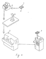
- the test procedure starts by identifying a cassette conveying a photostimulable phosphor screen, indicated by numeral (1) in figure 1, in an identification station (2).
- the cassette is provided with an electrically erasable programmable read only memory (3) (EEPROM).
- EEPROM electrically erasable programmable read only memory
- various kinds of data such as data relating to the read out conditions and/or data relating to the signal processing that is to be applied and/or to the destination of an image after read-out can be written into the EEPROM.
- the cassette is fed into the identification station and from a number of available processing menu's that are displayed on the monitor of the identification station, a test menu is selected. Then an identifier indicative of this menu item is written onto the EEPROM.
- the measurement phantom is positioned on top of a cassette conveying an unexposed photostimulable phosphor screen in such a way that the ruler strips are perpendicular to the direction of line-wise scanning (fast scanning direction).
- the correct position of the phantom is obtained by guiding means that serve to align the phantom with the cassette conveying the photostimulable phosphor screen.
- the phantom is provided with a number of recesses into which a cassette conveying a photostimulable phosphor screen can be positioned.
- a cassette format For each cassette format a corresponding recess is provided.
- the exposed photostimulable phosphor screen is then fed into a read-out apparatus (5) for reading the radiation image of the phantom.
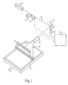
- FIG. 1 A simplified diagram illustrating the operation of the read-out apparatus is shown in figure 2.
- Read-out of an image stored in a photostimulable phosphor screen is performed by scanning the screen by means of a stimulating light beam 8 emitted by a light source 9 emitting light of a wavelength within the stimulating wavelength range of the phosphor used.
- a stimulating light beam 8 emitted by a light source 9 emitting light of a wavelength within the stimulating wavelength range of the phosphor used.
- a HeNe laser emitting at 633 nm is used.
- a fast scan movement is obtained by directing the light beam emitted by a laser towards an oscillating scan mirror 10 that is driven by a galvanometer.
- Computer 19 and drive means 18 control the galvanometer movement under control of a triangular wave pattern.
- a light chopper 12 with a rotating disc segment 13 is positioned in the laser beam path during the galvanometer retrace step.
- Various laser beam focusing devices such as an F-thèta lens, can be used to ensure a uniform beam diameter during scanning of the beam on the phosphor sheet and also ensure that the uniform angular velocity of the reciprocating mirror results in the laser spot travelling across the phosphor sheet at a uniform linear speed.
- the laser beam is one-dimensionally deflected in a line direction by the galvanometer mirror 10 and a plane reflection mirror 9.
- the movement of the laser beam in the line direction is commonly referred to as fast scan movement.
- the slow scan movement i.e. the movement in a direction perpendicular to the fast scan movement, is provided by means of transport means that transport the screen at a uniform speed of in a direction perpendicular to the main scan direction to enable the whole sheet to be scanned in a uniform manner (direction of arrow 15).
- a light guide 16 Positioned close to, but behind the scanning line of the laser beam on the phosphor sheet, is a light guide 16 that receives light emitted from the phosphor sheet but is shielded from direct exposure to the laser beam.
- the output end of the light guide is positioned adjacent a photo-detector 17, which produces an electrical signal dependent upon the light intensity falling there on. Suitable electrical connections are made to pass the output signal from the photo-detector to a computer 19.
- This computer serves to control the light chopper 12 and the galvanometer mirror drive 18.
- a sample and hold circuit and an analog-to-digital converter (not shown) are provided to convert the electric signal into a digital image signal.
- the digital image signal is then fed to an image processing module (not shown) of the read-out apparatus where it is stored on a system disc.
- the operation of the radiation image read-out apparatus is as follows. First the information stored in the EEPROM is read. In this way a test procedure is identified so that the image that will be read out is identified as a phantom image and will be analyzed according to a dedicated measurement procedure. Parameters to be used during execution of this dedicated measurement procedure are identified and can be retrieved from the system disc.
- the exposed screen is scanned by means of laser light of the appropriate stimulating wavelength and the image emitted upon stimulation is detected and converted into an digital image representation.
- the next is step is the analysis of the digital image of the measurement phantom so as to determine values for specific geometric parameters.
- the image of the ruler will be located at a fixed position within the image on the exposed screen up to some uncertainty, caused by some unavoidable inaccuracy of alignment.
- the image row index j r corresponding to the approximate position of the ruler center line for the actual cassette format, is stored in advance as one of the parameters that pertains to a measurement program.
- the row index j r is fetched from a system data table.
- This table is permanently stored in the file system of the image read out device, and it contains all fixed system parameters, including those describing the phantom geometry.
- a first step the digital image data pertaining to 2K+1 consecutive rows of the image are taken into account. These data are vertically averaged (i.e. data pertaining to the same column in each of these 2K+1 lines of the matrix of read out pixels are averaged) to reduce the effect of image noise.
- the following formula is applied to obtain average intensity values across the selected rows: where the horizontal coordinate i ranges from 0 through M-1. M is the number of pixels in each image row.
- the value of K is such that a band of 2K+1 pixels high, centered around the row with vertical coordinate j r , is about half as wide as the imaged height of the ruler strips.
- the parameter K is fetched from the system data table.
- g i,j are original image values
- m is an array representing average ruler intensity values m i across the image of the ruler.
- the horizontal coordinates i s of the ruler strips are computed.
- the average signal value m i is lower than between the strips. All segments of consecutive values of m i are considered that are below a threshold m T .
- the bounds of each of those segments are denoted by a s and b s respectively.
- the threshold value m T is computed as the average of the minimum and maximum of the values within the array of values m i .
- the centroid position of each segment is then computed as:
- the strip centroid coordinates c s are stored on the system disc as an array, indexed from 0 through S. A maximum of 71 strip locations will be found when a 35 cm wide image screen was used.
- Other techniques could be used to estimate the location of the ruler strips, but the centroid computation has the advantages of being quite unsensitive to noise and being precise as long as the intensity profile across the strip is symmetric, which is the case with the used kind of ruler.
- the average pixel sampling distance ⁇ x expressed in mm, is used to convert the measured distances (in pixel units or fractions thereof) into metric distances (mm).
- geometric distortion value of zero will be found along the whole scanning line. In practice however small deviations in scanning linearity will cause minor fluctuations in sampling distance.
- the computed geometric distortion values dx s at the strip with index s indicates the difference in mm between the actual strip position and the position computed from its horizontal coordinate in the image, assuming a constant pixel sampling distance equal to ⁇ x.
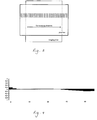
- FIG. 4 A plot of geometric distortion values as a function of s along the ruler is shown in Fig. 4.
- the parts of the plot where the local slope is negative indicate regions along the scanning line where the local sampling distance is larger than average.
- a positive slope at the other hand implies that the sampling distance is smaller than average.
- the geometric distortion value is zero at the center of the image.
- the position of the zero reference is fixed by convention, but a different convention could easily be adopted by adding an offset to each of the distortion values, such that e.g. either the left most or right most image pixel has zero distortion, or such that the average distortion along the line is zero.
- the following measured, computed, or stored parameters are communicated to the operator so that he can verify the geometric accuracy of the readout system: the array of geometric distortion values, the peak-to-peak geometric distortion value, the average sampling distance, the total scanned width, and the acceptance levels for these quantities.
- the peak-to-peak geometric distortion value is the difference between the most extreme positive and negative geometric distortion values.
- session identification number is incremented each time an image screen is read out.
- the geometric distortion value is plotted as a graph.
- the other parameters are presented in textual form.
- the image with the superimposed results is either printed on hard-copy film, or it is displayed on a CRT monitor.
- the film hardcopy is kept with the machine as a quality record.
- report files are also stored on the system hard disk of the readout system.
- the service technician can make a copy of these files onto a portable personal computer for archival in an electronic database. This way a historical overview of the status of individual machines can be maintained at the service department. Also statistics can be gathered concerning the accuracy of all installed machines.
Landscapes
- Multimedia (AREA)
- Signal Processing (AREA)
- Engineering & Computer Science (AREA)
- Physics & Mathematics (AREA)
- Optics & Photonics (AREA)
- Image Analysis (AREA)
- Apparatus For Radiation Diagnosis (AREA)
- Image Processing (AREA)
- Testing, Inspecting, Measuring Of Stereoscopic Televisions And Televisions (AREA)
- Facsimile Scanning Arrangements (AREA)
- Transforming Light Signals Into Electric Signals (AREA)
- Conversion Of X-Rays Into Visible Images (AREA)
- Radiography Using Non-Light Waves (AREA)
Claims (7)
- Verfahren zur Überprüfung der geometrischen Verzerrung eines Systems zum Auslesen eines Röntgenbildes durch zeilenweises Abtasten eines optisch anregbaren Leuchtstoffschirms, der mit dem besagten Röntgenbild belichtet wurde,
das durch die folgenden Schritte gekennzeichnet ist:(i) Positionieren eines Phantoms, das aus einem für Röntgenstrahlen durchlässigen Substrat und einem eingebetteten Lineal besteht, das aus mehreren in gleichem Abstand angeordneten parallelen Streifen besteht, die für Röntgenstrahlen undurchlässig sind, auf dem besagten Schirm, so daß das Lineal parallel zu der Richtung des zeilenweisen Abtastens liegt,(ii) Belichten einer Kombination aus Schirm und Phantom mit Röntgenstrahlen,(iii) Abtasten mindestens eines Teils des belichteten Schirms, der ein Röntgenbild des besagten Lineals umfaßt, mittels Anregungsbestrahlung, Erfassen von infolge der Anregung emittiertem Licht und Umsetzung des erfaßten Lichts in entsprechende elektrische Signalwerte, die ein digitales Bild darstellen,(iv) Bestimmung der Position jedes Streifens des besagten Lineals auf dem besagten digitalen Bild,(v) Bestimmung mindestens eines der folgenden Parameter:der mittlere Bildpunkt-Abtastabstand als das Verhältnis des nominalen Lineal-Teilungsabstands und des mittels der festgestellten Position jedes Streifens berechneten mittleren Abstands nebeneinanderliegender Linealstreifen in dem digitalen Bild,der geometrische Verzerrungswert an einem Streifen, d.h. die Differenz zwischen der festgestellten Position eines Linealstreifens in dem digitalen Bild und einer vorbestimmten Position eines Streifens. - Verfahren nach Anspruch 1, wobei an Bauteilen des Systems für zeilenweises Abtasten eines optisch anregbaren Leuchtstoffschirms Einstellungen vorgenommen werden, die eine Funktion einer Differenz zwischen den besagten bestimmten Parametern und Annehmbarkeitswerten sind.
- Verfahren nach Anspruch 1, wobei die Position eines Streifens des besagten Lineals durch Berechnung der Position der Mitte jedes Linealstreifens in der Abtastrichtung folgendermaßen bestimmt wird:Schwellenwertanalyse von Signalwerten, die zu Bildpunkten einer abgetasteten Zeile in dem digitalen Bild des besagten Lineals gehören, mittels eines Schwellenwerts mT, bei dem es sich um den Mittelwert des Minimums und des Maximums von Signalwerten handelt, die zu Bildpunkten der besagten abgetasteten Zeile gehören,Betrachtung aller Segmente entlang der besagten Zeile aufeinanderfolgender Signalwerte mi an Positionen i, die kleiner als der besagte Schwellenwert mT sind,Benennung von as als erster Bildpunkt und bs als letzter Bildpunkt in den besagten Segmenten,Berechnung der Position cs der Mitte eines Streifens gemäß

- Verfahren nach Anspruch 2, wobei jedoch Signalwerte, die zu Bildpunkten mit derselben Position in einer Abtastzeile gehören, über eine im voraus eingestellte Anzahl von Abtastzeilen in einem Bild des besagten Lineals gemittelt werden.
- Verfahren nach Anspruch 1, wobei die besagten bestimmten Parameter in einer Speicherungsvorrichtung in dem System zum Lesen eines Röntgenbildes gespeichert werden.
- Verfahren nach Anspruch 1, wobei zusätzlich zu einem sichtbaren Bild des Phantoms ein Überblendungsbild erzeugt wird, das mindestens einen der besagten Parameter und einen entsprechenden Annehmbarkeitswert umfaßt.
- Verfahren nach Anspruch 1, wobei der nominale Lineal-Teilungsabstand und der Zeilenindex jr, der der ungefähren Position einer Lineal-Mittellinie entspricht, aus einer einen Teil des besagten Systems zum Lesen eines Röntgenbildes bildenden Speicherungsvorrichtung abgerufen werden und wobei die besagten Parameter in dem besagten System bestimmt werden.
Priority Applications (4)
| Application Number | Priority Date | Filing Date | Title |
|---|---|---|---|
| EP94203122A EP0710013B1 (de) | 1994-10-27 | 1994-10-27 | Verfahren zur quantitativen Abtastgeometrieprüfung in einem digitalen radiographischen Wiedergabesystem |
| DE69408676T DE69408676T2 (de) | 1994-10-27 | 1994-10-27 | Verfahren zur quantitativen Abtastgeometrieprüfung in einem digitalen radiographischen Wiedergabesystem |
| JP7297260A JPH08307605A (ja) | 1994-10-27 | 1995-10-23 | デジタル放射線読出しシステムにおける走査形態の量的検証の方法 |
| US08/547,401 US5804819A (en) | 1994-10-27 | 1995-10-24 | Method for quantitative verification of scanning geometry in digital radiographic read out system |
Applications Claiming Priority (1)
| Application Number | Priority Date | Filing Date | Title |
|---|---|---|---|
| EP94203122A EP0710013B1 (de) | 1994-10-27 | 1994-10-27 | Verfahren zur quantitativen Abtastgeometrieprüfung in einem digitalen radiographischen Wiedergabesystem |
Publications (2)
| Publication Number | Publication Date |
|---|---|
| EP0710013A1 EP0710013A1 (de) | 1996-05-01 |
| EP0710013B1 true EP0710013B1 (de) | 1998-02-25 |
Family
ID=8217316
Family Applications (1)
| Application Number | Title | Priority Date | Filing Date |
|---|---|---|---|
| EP94203122A Expired - Lifetime EP0710013B1 (de) | 1994-10-27 | 1994-10-27 | Verfahren zur quantitativen Abtastgeometrieprüfung in einem digitalen radiographischen Wiedergabesystem |
Country Status (4)
| Country | Link |
|---|---|
| US (1) | US5804819A (de) |
| EP (1) | EP0710013B1 (de) |
| JP (1) | JPH08307605A (de) |
| DE (1) | DE69408676T2 (de) |
Families Citing this family (3)
| Publication number | Priority date | Publication date | Assignee | Title |
|---|---|---|---|---|
| US20040021101A1 (en) * | 2000-06-29 | 2004-02-05 | Essex Electro Engineers, Inc. | Method and apparatus for radiographic imaging |
| US6696698B2 (en) | 2000-06-29 | 2004-02-24 | Essex Electro Engineers, Inc. | Method and apparatus for radiographic imaging |
| US7256392B2 (en) * | 2003-03-03 | 2007-08-14 | Fujifilm Corporation | Inspection method of radiation imaging system and medical image processing apparatus using the same, and phantom for use of inspection of radiation imaging system |
Family Cites Families (5)
| Publication number | Priority date | Publication date | Assignee | Title |
|---|---|---|---|---|
| US3849650A (en) * | 1973-03-29 | 1974-11-19 | Picker Corp | Automatic x-ray inspection system |
| JPS62229830A (ja) * | 1986-03-28 | 1987-10-08 | Jeol Ltd | ハイブリツド用荷電粒子ビ−ム描画装置 |
| FR2633793A1 (fr) * | 1988-07-01 | 1990-01-05 | Gen Electric Cgr | Procede de correction de la distorsion d'images radiologiques |
| US5140418A (en) * | 1991-03-18 | 1992-08-18 | The United States Of America As Represented By The Secretary Of The Army | System for quantitatively evaluating imaging devices |
| US5420441A (en) * | 1993-11-23 | 1995-05-30 | Eastman Kodak Company | Automated technique for calibrating a storage phosphor reader |
-
1994
- 1994-10-27 EP EP94203122A patent/EP0710013B1/de not_active Expired - Lifetime
- 1994-10-27 DE DE69408676T patent/DE69408676T2/de not_active Expired - Lifetime
-
1995
- 1995-10-23 JP JP7297260A patent/JPH08307605A/ja active Pending
- 1995-10-24 US US08/547,401 patent/US5804819A/en not_active Expired - Lifetime
Also Published As
| Publication number | Publication date |
|---|---|
| EP0710013A1 (de) | 1996-05-01 |
| DE69408676T2 (de) | 1998-09-17 |
| US5804819A (en) | 1998-09-08 |
| DE69408676D1 (de) | 1998-04-02 |
| JPH08307605A (ja) | 1996-11-22 |
Similar Documents
| Publication | Publication Date | Title |
|---|---|---|
| EP1136843A2 (de) | Automatisiertes und quantitatives Verfahren zur Qualitätssicherung digitaler Röntgenbilderzeugungssysteme | |
| EP0658778A2 (de) | Automatische Eichungstechnik für einer Speicherleuchtschirmleser | |
| US4837733A (en) | Signal processing method in autoradiography | |
| US4804842A (en) | Radiation image read-out method and apparatus | |
| US5841148A (en) | Image processing apparatus | |
| US5533143A (en) | Method for determining the orientation in which an object was placed when the image of the object was recorded | |
| EP0598949A1 (de) | Verfahren zur Wiedergabe eines Strahlungsbildes | |
| US7504648B2 (en) | Method and apparatus for determining focus of a scanning system | |
| US4578581A (en) | Radiation image read-out method and apparatus | |
| US4992663A (en) | Method of judging the correctness or incorrectness of a prospective contour point of an irradiation field | |
| US5804819A (en) | Method for quantitative verification of scanning geometry in digital radiographic read out system | |
| US5874743A (en) | Method for verification of the frequency response of a digital radiographic read out system | |
| US5591968A (en) | Photostimulable imaging plate and method of testing a digital device for scanning such plate | |
| US5693954A (en) | Verification of the performance of photostimulable phosphor read out system | |
| US4862358A (en) | Signal processing method in autoradiography | |
| EP0710015B1 (de) | Leistungsprüfung für Systeme zum Auslesen von photostimulierbarem Leuchtstoff | |
| US8278637B2 (en) | Process and apparatus for reading out and erasing X-ray information stored in storage phosphor layers | |
| US7558438B1 (en) | System for synthesizing divisional images based on information indicating relationship between a series of divisional images | |
| EP0724167B1 (de) | Verfahren zur Qualitätssicherung von digitalen Röntgenaufnahmen | |
| JP2582561B2 (ja) | 放射線画像情報読取方法および装置 | |
| US5872830A (en) | Device and method of imaging or measuring of a radiation source | |
| EP0189206A2 (de) | Verfahren zur Anpassung des Auswertens eines Strahlungsbildes | |
| US4810887A (en) | Radiation image read-out method and apparatus | |
| JP2525648B2 (ja) | 放射線照射野輪郭候補点正誤判定方法 | |
| JP2001346795A (ja) | X線源と散乱線除去グリッドの位置合わせ評価方法およびフィードバック方法、フィードバック装置、x線撮影方法及びx線撮影装置 |
Legal Events
| Date | Code | Title | Description |
|---|---|---|---|
| PUAI | Public reference made under article 153(3) epc to a published international application that has entered the european phase |
Free format text: ORIGINAL CODE: 0009012 |
|
| AK | Designated contracting states |
Kind code of ref document: A1 Designated state(s): BE DE FR GB NL |
|
| 17P | Request for examination filed |
Effective date: 19941110 |
|
| 17Q | First examination report despatched |
Effective date: 19960801 |
|
| GRAG | Despatch of communication of intention to grant |
Free format text: ORIGINAL CODE: EPIDOS AGRA |
|
| GRAG | Despatch of communication of intention to grant |
Free format text: ORIGINAL CODE: EPIDOS AGRA |
|
| GRAH | Despatch of communication of intention to grant a patent |
Free format text: ORIGINAL CODE: EPIDOS IGRA |
|
| GRAH | Despatch of communication of intention to grant a patent |
Free format text: ORIGINAL CODE: EPIDOS IGRA |
|
| GRAA | (expected) grant |
Free format text: ORIGINAL CODE: 0009210 |
|
| AK | Designated contracting states |
Kind code of ref document: B1 Designated state(s): BE DE FR GB NL |
|
| REF | Corresponds to: |
Ref document number: 69408676 Country of ref document: DE Date of ref document: 19980402 |
|
| ET | Fr: translation filed | ||
| REG | Reference to a national code |
Ref country code: GB Ref legal event code: 746 Effective date: 19981014 |
|
| PLBE | No opposition filed within time limit |
Free format text: ORIGINAL CODE: 0009261 |
|
| STAA | Information on the status of an ep patent application or granted ep patent |
Free format text: STATUS: NO OPPOSITION FILED WITHIN TIME LIMIT |
|
| REG | Reference to a national code |
Ref country code: FR Ref legal event code: D6 |
|
| 26N | No opposition filed | ||
| PGFP | Annual fee paid to national office [announced via postgrant information from national office to epo] |
Ref country code: BE Payment date: 20010827 Year of fee payment: 8 |
|
| REG | Reference to a national code |
Ref country code: GB Ref legal event code: IF02 |
|
| PG25 | Lapsed in a contracting state [announced via postgrant information from national office to epo] |
Ref country code: BE Free format text: LAPSE BECAUSE OF NON-PAYMENT OF DUE FEES Effective date: 20021031 |
|
| BERE | Be: lapsed |
Owner name: *AGFA-GEVAERT N.V. Effective date: 20021031 |
|
| PGFP | Annual fee paid to national office [announced via postgrant information from national office to epo] |
Ref country code: NL Payment date: 20050922 Year of fee payment: 12 |
|
| REG | Reference to a national code |
Ref country code: GB Ref legal event code: 732E |
|
| PG25 | Lapsed in a contracting state [announced via postgrant information from national office to epo] |
Ref country code: NL Free format text: LAPSE BECAUSE OF NON-PAYMENT OF DUE FEES Effective date: 20070501 |
|
| NLV4 | Nl: lapsed or anulled due to non-payment of the annual fee |
Effective date: 20070501 |
|
| REG | Reference to a national code |
Ref country code: FR Ref legal event code: TP |
|
| PGFP | Annual fee paid to national office [announced via postgrant information from national office to epo] |
Ref country code: FR Payment date: 20130903 Year of fee payment: 20 |
|
| PGFP | Annual fee paid to national office [announced via postgrant information from national office to epo] |
Ref country code: DE Payment date: 20130909 Year of fee payment: 20 Ref country code: GB Payment date: 20131101 Year of fee payment: 20 |
|
| REG | Reference to a national code |
Ref country code: DE Ref legal event code: R071 Ref document number: 69408676 Country of ref document: DE |
|
| REG | Reference to a national code |
Ref country code: GB Ref legal event code: PE20 Expiry date: 20141026 |
|
| PG25 | Lapsed in a contracting state [announced via postgrant information from national office to epo] |
Ref country code: GB Free format text: LAPSE BECAUSE OF EXPIRATION OF PROTECTION Effective date: 20141026 |