EP0710065A1 - Einschub für elektronischen Karten - Google Patents
Einschub für elektronischen Karten Download PDFInfo
- Publication number
- EP0710065A1 EP0710065A1 EP95402368A EP95402368A EP0710065A1 EP 0710065 A1 EP0710065 A1 EP 0710065A1 EP 95402368 A EP95402368 A EP 95402368A EP 95402368 A EP95402368 A EP 95402368A EP 0710065 A1 EP0710065 A1 EP 0710065A1
- Authority
- EP
- European Patent Office
- Prior art keywords
- drawer
- motherboards
- compartment
- connectors
- electronic cards
- Prior art date
- Legal status (The legal status is an assumption and is not a legal conclusion. Google has not performed a legal analysis and makes no representation as to the accuracy of the status listed.)
- Granted
Links
- 125000006850 spacer group Chemical group 0.000 claims description 7
- 230000000712 assembly Effects 0.000 description 6
- 238000000429 assembly Methods 0.000 description 6
- 238000009434 installation Methods 0.000 description 5
- 241001441732 Ostraciidae Species 0.000 description 4
- 230000003416 augmentation Effects 0.000 description 4
- 230000006978 adaptation Effects 0.000 description 3
- 230000001681 protective effect Effects 0.000 description 3
- 240000008042 Zea mays Species 0.000 description 2
- 241001310793 Podium Species 0.000 description 1
- 241001080024 Telles Species 0.000 description 1
- XAGFODPZIPBFFR-UHFFFAOYSA-N aluminium Chemical compound [Al] XAGFODPZIPBFFR-UHFFFAOYSA-N 0.000 description 1
- 229910052782 aluminium Inorganic materials 0.000 description 1
- 230000010354 integration Effects 0.000 description 1
- 230000035939 shock Effects 0.000 description 1
Images


Classifications
-
- H—ELECTRICITY
- H05—ELECTRIC TECHNIQUES NOT OTHERWISE PROVIDED FOR
- H05K—PRINTED CIRCUITS; CASINGS OR CONSTRUCTIONAL DETAILS OF ELECTRIC APPARATUS; MANUFACTURE OF ASSEMBLAGES OF ELECTRICAL COMPONENTS
- H05K7/00—Constructional details common to different types of electric apparatus
- H05K7/14—Mounting supporting structure in casing or on frame or rack
- H05K7/1438—Back panels or connecting means therefor; Terminals; Coding means to avoid wrong insertion
- H05K7/1439—Back panel mother boards
- H05K7/1444—Complex or three-dimensional-arrangements; Stepped or dual mother boards
-
- H—ELECTRICITY
- H05—ELECTRIC TECHNIQUES NOT OTHERWISE PROVIDED FOR
- H05K—PRINTED CIRCUITS; CASINGS OR CONSTRUCTIONAL DETAILS OF ELECTRIC APPARATUS; MANUFACTURE OF ASSEMBLAGES OF ELECTRICAL COMPONENTS
- H05K7/00—Constructional details common to different types of electric apparatus
- H05K7/14—Mounting supporting structure in casing or on frame or rack
- H05K7/1438—Back panels or connecting means therefor; Terminals; Coding means to avoid wrong insertion
- H05K7/1452—Mounting of connectors; Switching; Reinforcing of back panels
- H05K7/1454—Alignment mechanisms; Drawout cases
-
- H—ELECTRICITY
- H05—ELECTRIC TECHNIQUES NOT OTHERWISE PROVIDED FOR
- H05K—PRINTED CIRCUITS; CASINGS OR CONSTRUCTIONAL DETAILS OF ELECTRIC APPARATUS; MANUFACTURE OF ASSEMBLAGES OF ELECTRICAL COMPONENTS
- H05K1/00—Printed circuits
- H05K1/02—Details
- H05K1/14—Structural association of two or more printed circuits
Definitions
- the present invention relates to electronic card support assemblies, in general, and relates, more particularly, to a drawer for electronic cards and its trunk.
- a first category of these supports is made up of standardized sets. They use drawers for electronic cards known as the "Eurofer” drawer.
- Electronic cards are mounted perpendicular to the front face of these drawers and are guided by slides.
- These electronic cards are capable of being connected to electrical connectors secured to the rear face of the drawers.
- These electrical connectors provide the electrical connections between the cards and / or between the cards and the outside.
- This first category of sets of electronic card holders is self-withdrawing.
- a second category of electronic card support assemblies includes a first solution consisting in having a large motherboard on which the electronic cards are arranged.
- the card connectors are attached to the motherboard.
- Output connectors facing the front of the trunk are attached to the sides of the large motherboard.
- Another solution of the electronic card support assemblies of this category consists in placing the output connectors on the front of the electronic cards.
- Connectors mounted on a motherboard and placed at the back of the electronic cards allow connections between cards.
- An object of the invention is the design of a drawer for electronic cards which does not have the drawbacks of the support assemblies of the prior art.
- the invention relates to a drawer for electronic cards, said electronic cards being connected to motherboards, said motherboards being arranged on at least two planes and is characterized in that each plan comprises one or more motherboards parallel to the front face of said drawer, said motherboards and their electronic cards being superimposed on one another, so as to form a superposition of compartments of general pyramidal shape.
- the electronic cards are connected to motherboards 3A-3C.
- the motherboards are arranged on at least two planes.
- Each of these plans includes one or more motherboards 3A-3C parallel to the front face 6 of the drawer, the motherboards and their electronic cards are superimposed on each other, so as to form a superposition of compartments A-C of generally pyramidal shape.
- the motherboards 3A-3C preferably have, on at least one of their sides, connectors 4A-4C capable of accommodating output connectors 5A-5C.
- the connectors of a compartment are offset from the connectors of any of the other compartments so that the connectors are not arranged one above the other and are accessible from the front face of the drawer.
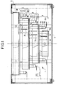
- Figures 1 and 2 show two top views in partial section of a first preferred embodiment of the drawer for electronic cards having three compartments according to the invention.
- the drawer 1 for electronic cards comprises electronic cards 2A-2C, also called daughter electronic cards, connected to motherboards 3A-3C.
- the motherboards are arranged on at least two planes parallel to a front face 6 of a box 9, each plane comprising one or more motherboards.
- the planes are superimposed on each other, so as to form a pyramid-shaped stack, the top of the stack being formed by the motherboard or the set of motherboards with the smallest area.
- Drawer 1 for electronic cards 2A-2C therefore has large motherboards 3A-3C on the short sides of which female connectors 4A-4C are fixed.
- Male 5A-5C output connectors can be manually connected to female 4A-4C connectors. These 5A-5C male output connectors are integral with 10A-10C output wiring.
- Each motherboard model has one or more female connectors.
- All the motherboards are arranged parallel to the plane of the front face 6 of the box 9 so as to form a stack of several compartments A-C of motherboards.
- the set of motherboards is arranged and maintained so as to form a pyramid-shaped stack.
- the outer fictitious envelope defined by the set of motherboards consists of a succession of steps along the longitudinal axis and / or along the radial axis for form a podium along one and / or the other of these axes.
- the front face 6 of the trunk 9 is arranged facing the motherboard, or all the motherboards of the same plane, with the smallest area.
- the realization of the drawer for electronic cards of the invention requires to fix the different motherboards to each other by means of spacers 7A-7C.
- spacers 7A-7C are preferably integral with stiffening plates 8B-8D of the motherboards 3A-3C and / or protective plates 8A-8C on the electronic daughter boards 2A-2C.
- the drawer as defined may include at least two 3A-3C motherboards electrically connected to each other by means of at least one of the 2A-2C electronic cards.
- the electronic card concerned preferably includes automatic connection means with at least one of the motherboards.
- FIG. 2 shows a partial sectional front view of a first preferred embodiment of the drawer for electronic cards according to the invention in which the front face 6 of the trunk 9 is not shown.
- the entire drawer is capable of being positioned in the trunk 9 on which the front face is fixed.
- the overall size, mass and cost of the drawer for electronic cards can be adjusted beforehand as required.
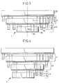
- Figure 3 is a top view in partial section of the drawer 1 for electronic cards 2 illustrating a particular arrangement between the motherboard 3B of the second compartment and the first compartment A.
- the removal of the motherboard from the first compartment A and the stiffening and protection plate from the second compartment B provides four rows of connectors 4A, 5A and 4B, 5B on the motherboard 3B of the second compartment B and, as obtained in the previous embodiment, two rows of connectors 4C, 5C on the motherboard 3C of the third compartment C.
- plates 8C and 8D for stiffening motherboards 3B, 3C as well as the protective plates 8A, 8C for electronic cards 2B and 2C.
- Figure 4 is a top view in partial section of the drawer 1 for electronic cards illustrating an arrangement between the first compartment A and the second compartment B allowing to have all the connectors 4A, 5A of the motherboard 3A of the first compartment A on the one of the sides of the drawer 1 or, more precisely, on one of the sides of the motherboard 3A of the first compartment A.
- Such an arrangement makes it possible to arrange the connectors more particularly on one end of one of the motherboards.
- compartments A and B are aligned with respect to one of the other compartments, for example compartment C, so as to distribute the compartments according to another arrangement.
- FIG. 5 Such an embodiment is shown in FIG. 5.
- the output connectors are wave soldered on the motherboards.
- the drawer is fixed to its trunk by means of several screws.
- the plates 8A-8D can be adapted and associated with each compartment to take up the cards of the compartment concerned and thus ensure higher performance in terms of vibration and shock but also serve as a heat shield between the compartments.
- a drawer comprising such frames allows the fixing to be resumed on its trunk by means of screws preferably placed at the level of the third compartment on the plate 8D.
Landscapes
- Engineering & Computer Science (AREA)
- Microelectronics & Electronic Packaging (AREA)
- Mounting Of Printed Circuit Boards And The Like (AREA)
- Coupling Device And Connection With Printed Circuit (AREA)
- Combinations Of Printed Boards (AREA)
- Credit Cards Or The Like (AREA)
- Control And Other Processes For Unpacking Of Materials (AREA)
- Packaging For Recording Disks (AREA)
- Casings For Electric Apparatus (AREA)
- Electrochromic Elements, Electrophoresis, Or Variable Reflection Or Absorption Elements (AREA)
Applications Claiming Priority (2)
| Application Number | Priority Date | Filing Date | Title |
|---|---|---|---|
| FR9412879A FR2726427B1 (fr) | 1994-10-27 | 1994-10-27 | Tiroir pour cartes electroniques |
| FR9412879 | 1994-10-27 |
Publications (2)
| Publication Number | Publication Date |
|---|---|
| EP0710065A1 true EP0710065A1 (de) | 1996-05-01 |
| EP0710065B1 EP0710065B1 (de) | 1998-10-07 |
Family
ID=9468279
Family Applications (1)
| Application Number | Title | Priority Date | Filing Date |
|---|---|---|---|
| EP95402368A Expired - Lifetime EP0710065B1 (de) | 1994-10-27 | 1995-10-24 | Einschub für elektronische Karten |
Country Status (12)
| Country | Link |
|---|---|
| US (1) | US5712769A (de) |
| EP (1) | EP0710065B1 (de) |
| JP (1) | JPH08213777A (de) |
| CN (1) | CN1066605C (de) |
| AT (1) | ATE172073T1 (de) |
| AU (1) | AU696061B2 (de) |
| CA (1) | CA2161485A1 (de) |
| DE (1) | DE69505222T2 (de) |
| DK (1) | DK0710065T3 (de) |
| ES (1) | ES2122481T3 (de) |
| FR (1) | FR2726427B1 (de) |
| MX (1) | MX9504450A (de) |
Cited By (1)
| Publication number | Priority date | Publication date | Assignee | Title |
|---|---|---|---|---|
| EP0785706A1 (de) * | 1996-01-19 | 1997-07-23 | Gec Alsthom Transport Sa | Einschub für elektronische Karten mit automatischem Einstecken und Trennen, Einschub und sein Aufnahmestruktur, Demontageverfahren von elektronischen Karten |
Families Citing this family (2)
| Publication number | Priority date | Publication date | Assignee | Title |
|---|---|---|---|---|
| US6254437B1 (en) | 1999-02-02 | 2001-07-03 | Thomas & Betts International | Utility metering transocket |
| US6665194B1 (en) | 2000-11-09 | 2003-12-16 | International Business Machines Corporation | Chip package having connectors on at least two sides |
Citations (4)
| Publication number | Priority date | Publication date | Assignee | Title |
|---|---|---|---|---|
| EP0213205A1 (de) * | 1984-12-28 | 1987-03-11 | Micro Co., Ltd. | Stapelverfahren für gedruckte schaltungen |
| DE8910752U1 (de) * | 1989-09-07 | 1989-11-02 | Siemens AG, 1000 Berlin und 8000 München | Daten-Testgerät |
| US5040992A (en) * | 1988-12-06 | 1991-08-20 | Hitachi, Ltd. | Mounting structure for electronic device |
| US5259784A (en) * | 1991-06-10 | 1993-11-09 | Nec Corporation | Printed circuit board assembly of vertical and horizontal printed boards |
Family Cites Families (1)
| Publication number | Priority date | Publication date | Assignee | Title |
|---|---|---|---|---|
| US5575686A (en) * | 1993-04-14 | 1996-11-19 | Burndy Corporation | Stacked printed circuit boards connected in series |
-
1994
- 1994-10-27 FR FR9412879A patent/FR2726427B1/fr not_active Expired - Fee Related
-
1995
- 1995-10-20 MX MX9504450A patent/MX9504450A/es unknown
- 1995-10-24 DK DK95402368T patent/DK0710065T3/da active
- 1995-10-24 EP EP95402368A patent/EP0710065B1/de not_active Expired - Lifetime
- 1995-10-24 DE DE69505222T patent/DE69505222T2/de not_active Expired - Fee Related
- 1995-10-24 US US08/547,135 patent/US5712769A/en not_active Expired - Fee Related
- 1995-10-24 ES ES95402368T patent/ES2122481T3/es not_active Expired - Lifetime
- 1995-10-24 AT AT95402368T patent/ATE172073T1/de not_active IP Right Cessation
- 1995-10-25 AU AU34443/95A patent/AU696061B2/en not_active Ceased
- 1995-10-26 CN CN95120309A patent/CN1066605C/zh not_active Expired - Fee Related
- 1995-10-26 CA CA002161485A patent/CA2161485A1/fr not_active Abandoned
- 1995-10-27 JP JP7280510A patent/JPH08213777A/ja active Pending
Patent Citations (4)
| Publication number | Priority date | Publication date | Assignee | Title |
|---|---|---|---|---|
| EP0213205A1 (de) * | 1984-12-28 | 1987-03-11 | Micro Co., Ltd. | Stapelverfahren für gedruckte schaltungen |
| US5040992A (en) * | 1988-12-06 | 1991-08-20 | Hitachi, Ltd. | Mounting structure for electronic device |
| DE8910752U1 (de) * | 1989-09-07 | 1989-11-02 | Siemens AG, 1000 Berlin und 8000 München | Daten-Testgerät |
| US5259784A (en) * | 1991-06-10 | 1993-11-09 | Nec Corporation | Printed circuit board assembly of vertical and horizontal printed boards |
Cited By (4)
| Publication number | Priority date | Publication date | Assignee | Title |
|---|---|---|---|---|
| EP0785706A1 (de) * | 1996-01-19 | 1997-07-23 | Gec Alsthom Transport Sa | Einschub für elektronische Karten mit automatischem Einstecken und Trennen, Einschub und sein Aufnahmestruktur, Demontageverfahren von elektronischen Karten |
| FR2743977A1 (fr) * | 1996-01-19 | 1997-07-25 | Gec Alsthom Transport Sa | Tiroir pour cartes electroniques a embrochement et debrochage automatiques et tiroir et son coffre |
| US5885089A (en) * | 1996-01-19 | 1999-03-23 | Gec Alsthom Transport Sa | Drawer for automatically pluggable and unpluggable electronic cards, a drawer and a bay therefor, and a method of removing electronic cards |
| AU704464B2 (en) * | 1996-01-19 | 1999-04-22 | Alstom Transport Technologies | A drawer for automatically pluggable and unpluggable electronic cards, a drawer and a bay therefor, and a method of removing electronic cards |
Also Published As
| Publication number | Publication date |
|---|---|
| MX9504450A (es) | 1997-01-31 |
| AU696061B2 (en) | 1998-08-27 |
| ATE172073T1 (de) | 1998-10-15 |
| DK0710065T3 (da) | 1999-06-21 |
| CN1066605C (zh) | 2001-05-30 |
| FR2726427A1 (fr) | 1996-05-03 |
| EP0710065B1 (de) | 1998-10-07 |
| FR2726427B1 (fr) | 1996-12-13 |
| JPH08213777A (ja) | 1996-08-20 |
| CA2161485A1 (fr) | 1996-04-28 |
| DE69505222D1 (de) | 1998-11-12 |
| CN1132465A (zh) | 1996-10-02 |
| DE69505222T2 (de) | 1999-04-08 |
| US5712769A (en) | 1998-01-27 |
| AU3444395A (en) | 1996-05-09 |
| ES2122481T3 (es) | 1998-12-16 |
Similar Documents
| Publication | Publication Date | Title |
|---|---|---|
| US3188524A (en) | High density circuit card packaging | |
| USD383139S (en) | External modem enclosure for a data processing system | |
| EP0196726A1 (de) | Aus stapelbaren Modulen bestehendes elektronisches System | |
| FR2566221A1 (fr) | Dispositif d'assemblage mecanique et electrique pour cartes electroniques informatiques a haute integration | |
| EP1271712A2 (de) | Adapter für orientierten optischen Verbinder | |
| EP3551501B1 (de) | Wärmeableitungsvorrichtung für eine multimedia-steuereinheit | |
| KR930009186A (ko) | 모듈을 호환할 수 있는 배전 시스템 | |
| BE1005298A5 (fr) | Systeme adaptatif de montage de cartes. | |
| EP1148598A3 (de) | Adaptergehäuse für elektrische Steckverbinder | |
| JP2000506316A (ja) | 電気機器のモジュール | |
| FR2509563A1 (fr) | Dispositif support de circuits integres utilise dans un systeme de selection de circuits integres a haute fiabilite | |
| HK52995A (en) | Connector device | |
| EP0710065B1 (de) | Einschub für elektronische Karten | |
| FR2652229A1 (fr) | Ensemble de blindage pour un bloc collecteur relie a un equipement electrique place a l'interieur d'un chassis. | |
| EP0710066B1 (de) | Einschub für elektronische Karten und sein Träger | |
| EP1698979A2 (de) | Gerät zur Verbindung eines Mainboards zu einer Speicherkarte mit zwei Serien von Speichermodulen | |
| US5632656A (en) | Expandable surface mount box for transmission line connectors | |
| EP2764762B1 (de) | Rechnervorrichtung zum vorübergehenden einsatz in ein computergehäuse und zum anschluss an elektronische vorrichtungen | |
| WO2002054552A1 (fr) | Systeme de ventilation pour armoire technique | |
| EP1346447B1 (de) | Integriertes verdrahtungssystem für ein elektrisches gehäuse | |
| EP0188965A1 (de) | Aufnahmerahmen für elektronische Karte, geeignet zu einer stirnseitigen elektrischen Verbindung | |
| FR2700069A1 (fr) | Système d'interconnexion de cartes d'un système informatique rapide. | |
| EP0485282B1 (de) | Schutzvorrichtung für eine signalverarbeitende Einheit gegen elektromagnetische Störungen | |
| EP2506596B1 (de) | Kabelverbindungsvorrichtung | |
| FR2728109A1 (fr) | Dispositif de protection des connecteurs d'un tiroir pour cartes electroniques a embrochement et debrochage automatiques, tiroir incorporant un tel dispositif et procede d'insertion et d'extraction d'un tel tiroir |
Legal Events
| Date | Code | Title | Description |
|---|---|---|---|
| PUAI | Public reference made under article 153(3) epc to a published international application that has entered the european phase |
Free format text: ORIGINAL CODE: 0009012 |
|
| AK | Designated contracting states |
Kind code of ref document: A1 Designated state(s): AT BE CH DE DK ES FR GB GR IE IT LI LU MC NL PT SE |
|
| 17P | Request for examination filed |
Effective date: 19961012 |
|
| GRAG | Despatch of communication of intention to grant |
Free format text: ORIGINAL CODE: EPIDOS AGRA |
|
| GRAG | Despatch of communication of intention to grant |
Free format text: ORIGINAL CODE: EPIDOS AGRA |
|
| GRAH | Despatch of communication of intention to grant a patent |
Free format text: ORIGINAL CODE: EPIDOS IGRA |
|
| 17Q | First examination report despatched |
Effective date: 19980331 |
|
| GRAH | Despatch of communication of intention to grant a patent |
Free format text: ORIGINAL CODE: EPIDOS IGRA |
|
| GRAA | (expected) grant |
Free format text: ORIGINAL CODE: 0009210 |
|
| AK | Designated contracting states |
Kind code of ref document: B1 Designated state(s): AT BE CH DE DK ES FR GB GR IE IT LI LU MC NL PT SE |
|
| REF | Corresponds to: |
Ref document number: 172073 Country of ref document: AT Date of ref document: 19981015 Kind code of ref document: T |
|
| REG | Reference to a national code |
Ref country code: CH Ref legal event code: EP |
|
| REF | Corresponds to: |
Ref document number: 69505222 Country of ref document: DE Date of ref document: 19981112 |
|
| REG | Reference to a national code |
Ref country code: CH Ref legal event code: NV Representative=s name: CABINET ROLAND NITHARDT CONSEILS EN PROPRIETE INDU |
|
| REG | Reference to a national code |
Ref country code: IE Ref legal event code: FG4D Free format text: FRENCH Ref country code: ES Ref legal event code: FG2A Ref document number: 2122481 Country of ref document: ES Kind code of ref document: T3 |
|
| GBT | Gb: translation of ep patent filed (gb section 77(6)(a)/1977) |
Effective date: 19981127 |
|
| REG | Reference to a national code |
Ref country code: PT Ref legal event code: SC4A Free format text: AVAILABILITY OF NATIONAL TRANSLATION Effective date: 19981112 |
|
| REG | Reference to a national code |
Ref country code: DK Ref legal event code: T3 |
|
| PLBE | No opposition filed within time limit |
Free format text: ORIGINAL CODE: 0009261 |
|
| STAA | Information on the status of an ep patent application or granted ep patent |
Free format text: STATUS: NO OPPOSITION FILED WITHIN TIME LIMIT |
|
| 26N | No opposition filed | ||
| PGFP | Annual fee paid to national office [announced via postgrant information from national office to epo] |
Ref country code: GB Payment date: 20000915 Year of fee payment: 6 |
|
| PGFP | Annual fee paid to national office [announced via postgrant information from national office to epo] |
Ref country code: MC Payment date: 20000918 Year of fee payment: 6 |
|
| PGFP | Annual fee paid to national office [announced via postgrant information from national office to epo] |
Ref country code: IE Payment date: 20000921 Year of fee payment: 6 Ref country code: CH Payment date: 20000921 Year of fee payment: 6 |
|
| PGFP | Annual fee paid to national office [announced via postgrant information from national office to epo] |
Ref country code: NL Payment date: 20000925 Year of fee payment: 6 |
|
| PGFP | Annual fee paid to national office [announced via postgrant information from national office to epo] |
Ref country code: AT Payment date: 20000926 Year of fee payment: 6 |
|
| PGFP | Annual fee paid to national office [announced via postgrant information from national office to epo] |
Ref country code: LU Payment date: 20000927 Year of fee payment: 6 |
|
| PGFP | Annual fee paid to national office [announced via postgrant information from national office to epo] |
Ref country code: PT Payment date: 20000929 Year of fee payment: 6 |
|
| PGFP | Annual fee paid to national office [announced via postgrant information from national office to epo] |
Ref country code: SE Payment date: 20001002 Year of fee payment: 6 Ref country code: DK Payment date: 20001002 Year of fee payment: 6 |
|
| PGFP | Annual fee paid to national office [announced via postgrant information from national office to epo] |
Ref country code: DE Payment date: 20001005 Year of fee payment: 6 |
|
| PGFP | Annual fee paid to national office [announced via postgrant information from national office to epo] |
Ref country code: FR Payment date: 20001012 Year of fee payment: 6 |
|
| PGFP | Annual fee paid to national office [announced via postgrant information from national office to epo] |
Ref country code: ES Payment date: 20001020 Year of fee payment: 6 Ref country code: BE Payment date: 20001020 Year of fee payment: 6 |
|
| PGFP | Annual fee paid to national office [announced via postgrant information from national office to epo] |
Ref country code: GR Payment date: 20001023 Year of fee payment: 6 |
|
| PG25 | Lapsed in a contracting state [announced via postgrant information from national office to epo] |
Ref country code: MC Free format text: LAPSE BECAUSE OF NON-PAYMENT OF DUE FEES Effective date: 20011024 Ref country code: LU Free format text: LAPSE BECAUSE OF NON-PAYMENT OF DUE FEES Effective date: 20011024 Ref country code: IE Free format text: LAPSE BECAUSE OF FAILURE TO SUBMIT A TRANSLATION OF THE DESCRIPTION OR TO PAY THE FEE WITHIN THE PRESCRIBED TIME-LIMIT Effective date: 20011024 Ref country code: GB Free format text: LAPSE BECAUSE OF NON-PAYMENT OF DUE FEES Effective date: 20011024 Ref country code: DK Free format text: LAPSE BECAUSE OF NON-PAYMENT OF DUE FEES Effective date: 20011024 Ref country code: AT Free format text: LAPSE BECAUSE OF NON-PAYMENT OF DUE FEES Effective date: 20011024 |
|
| PG25 | Lapsed in a contracting state [announced via postgrant information from national office to epo] |
Ref country code: SE Free format text: LAPSE BECAUSE OF NON-PAYMENT OF DUE FEES Effective date: 20011025 Ref country code: ES Free format text: LAPSE BECAUSE OF NON-PAYMENT OF DUE FEES Effective date: 20011025 |
|
| PG25 | Lapsed in a contracting state [announced via postgrant information from national office to epo] |
Ref country code: LI Free format text: LAPSE BECAUSE OF NON-PAYMENT OF DUE FEES Effective date: 20011031 Ref country code: GR Free format text: LAPSE BECAUSE OF NON-PAYMENT OF DUE FEES Effective date: 20011031 Ref country code: CH Free format text: LAPSE BECAUSE OF NON-PAYMENT OF DUE FEES Effective date: 20011031 Ref country code: BE Free format text: LAPSE BECAUSE OF NON-PAYMENT OF DUE FEES Effective date: 20011031 |
|
| REG | Reference to a national code |
Ref country code: GB Ref legal event code: IF02 |
|
| BERE | Be: lapsed |
Owner name: S.A. GEC ALSTHOM TRANSPORT Effective date: 20011031 |
|
| PG25 | Lapsed in a contracting state [announced via postgrant information from national office to epo] |
Ref country code: PT Free format text: LAPSE BECAUSE OF NON-PAYMENT OF DUE FEES Effective date: 20020430 |
|
| PG25 | Lapsed in a contracting state [announced via postgrant information from national office to epo] |
Ref country code: NL Free format text: LAPSE BECAUSE OF NON-PAYMENT OF DUE FEES Effective date: 20020501 |
|
| EUG | Se: european patent has lapsed |
Ref document number: 95402368.5 |
|
| REG | Reference to a national code |
Ref country code: DK Ref legal event code: EBP |
|
| GBPC | Gb: european patent ceased through non-payment of renewal fee |
Effective date: 20011024 |
|
| REG | Reference to a national code |
Ref country code: CH Ref legal event code: PL |
|
| PG25 | Lapsed in a contracting state [announced via postgrant information from national office to epo] |
Ref country code: FR Free format text: LAPSE BECAUSE OF NON-PAYMENT OF DUE FEES Effective date: 20020628 |
|
| NLV4 | Nl: lapsed or anulled due to non-payment of the annual fee |
Effective date: 20020501 |
|
| PG25 | Lapsed in a contracting state [announced via postgrant information from national office to epo] |
Ref country code: DE Free format text: LAPSE BECAUSE OF NON-PAYMENT OF DUE FEES Effective date: 20020702 |
|
| REG | Reference to a national code |
Ref country code: IE Ref legal event code: MM4A |
|
| REG | Reference to a national code |
Ref country code: FR Ref legal event code: ST |
|
| REG | Reference to a national code |
Ref country code: PT Ref legal event code: MM4A Free format text: LAPSE DUE TO NON-PAYMENT OF FEES Effective date: 20020430 |
|
| REG | Reference to a national code |
Ref country code: ES Ref legal event code: FD2A Effective date: 20021113 |
|
| PG25 | Lapsed in a contracting state [announced via postgrant information from national office to epo] |
Ref country code: IT Free format text: LAPSE BECAUSE OF NON-PAYMENT OF DUE FEES;WARNING: LAPSES OF ITALIAN PATENTS WITH EFFECTIVE DATE BEFORE 2007 MAY HAVE OCCURRED AT ANY TIME BEFORE 2007. THE CORRECT EFFECTIVE DATE MAY BE DIFFERENT FROM THE ONE RECORDED. Effective date: 20051024 |