EP0710086B1 - Vorrichtung und verfahren zum messen und verarbeiten von physiologischen signalen - Google Patents
Vorrichtung und verfahren zum messen und verarbeiten von physiologischen signalen Download PDFInfo
- Publication number
- EP0710086B1 EP0710086B1 EP94922303A EP94922303A EP0710086B1 EP 0710086 B1 EP0710086 B1 EP 0710086B1 EP 94922303 A EP94922303 A EP 94922303A EP 94922303 A EP94922303 A EP 94922303A EP 0710086 B1 EP0710086 B1 EP 0710086B1
- Authority
- EP
- European Patent Office
- Prior art keywords
- electrodes
- patient
- values
- signals
- pam
- Prior art date
- Legal status (The legal status is an assumption and is not a legal conclusion. Google has not performed a legal analysis and makes no representation as to the accuracy of the status listed.)
- Expired - Lifetime
Links
Images




Classifications
-
- A—HUMAN NECESSITIES
- A61—MEDICAL OR VETERINARY SCIENCE; HYGIENE
- A61B—DIAGNOSIS; SURGERY; IDENTIFICATION
- A61B5/00—Measuring for diagnostic purposes; Identification of persons
- A61B5/24—Detecting, measuring or recording bioelectric or biomagnetic signals of the body or parts thereof
- A61B5/316—Modalities, i.e. specific diagnostic methods
- A61B5/318—Heart-related electrical modalities, e.g. electrocardiography [ECG]
- A61B5/332—Portable devices specially adapted therefor
-
- A—HUMAN NECESSITIES
- A61—MEDICAL OR VETERINARY SCIENCE; HYGIENE
- A61B—DIAGNOSIS; SURGERY; IDENTIFICATION
- A61B5/00—Measuring for diagnostic purposes; Identification of persons
- A61B5/05—Detecting, measuring or recording for diagnosis by means of electric currents or magnetic fields; Measuring using microwaves or radio waves
- A61B5/053—Measuring electrical impedance or conductance of a portion of the body
- A61B5/0535—Impedance plethysmography
-
- A—HUMAN NECESSITIES
- A61—MEDICAL OR VETERINARY SCIENCE; HYGIENE
- A61B—DIAGNOSIS; SURGERY; IDENTIFICATION
- A61B5/00—Measuring for diagnostic purposes; Identification of persons
- A61B5/72—Signal processing specially adapted for physiological signals or for diagnostic purposes
- A61B5/7232—Signal processing specially adapted for physiological signals or for diagnostic purposes involving compression of the physiological signal, e.g. to extend the signal recording period
-
- A—HUMAN NECESSITIES
- A61—MEDICAL OR VETERINARY SCIENCE; HYGIENE
- A61B—DIAGNOSIS; SURGERY; IDENTIFICATION
- A61B5/00—Measuring for diagnostic purposes; Identification of persons
- A61B5/72—Signal processing specially adapted for physiological signals or for diagnostic purposes
- A61B5/7235—Details of waveform analysis
- A61B5/7239—Details of waveform analysis using differentiation including higher order derivatives
Definitions
- the present invention relates to the field of medical examinations, more particularly long-term medical follow-up and diagnostic assistance, and relates to a device for acquiring, measuring and processing signals physiological as well as an automatic process implemented by said device.
- cardiac output and pressure or blood pressure blood pressure are measured by separate devices and only at important time intervals and under conditions particular, namely during medical consultations or examinations by specialized personnel.
- the cardiac output measured, in general, using invasive methods, requires equipment heavy and cannot be determined continuously over a significant period.
- the present invention does not relate to the electronic processing of electrical signals but a mode of acquisition of physiological signals by means of a single sensor which measures not an average but the variations of a characteristic value.
- the object of the present invention is in particular to overcome all of the drawbacks cited above.
- physiological signals for the determination of cardiac parameters and circulatory characterized in that it comprises means, on the one hand of acquisition, of formatting and digitization, in the form of integrated circuits of a signal and a signal representing the variation of the impedance of a determined volume of a patient's body connected to electrodes arranged in specific locations on the latter, on the other hand by a preprocessing unit digital cooperating with control and display means and a means of removable storage and / or a means of transmission of all the signals digitized or values extracted from significant parameters, for each beat cardiac, from said digital signals and, finally, by a central device for digital processing collecting and storing, by successive transfers, the data from the storage or transmission means and allowing the analysis said data or said parameters over significant time periods, their comparison with data or previous parameter values and display and / or printing of all the data that can be used for the development of a diagnostic, the acquisition means being arranged in a first housing connected to the electrodes and in that the preprocessing
- the invention also relates to an automatic method for measuring and physiological signal processing for the determination of cardiac parameters and circulatory, consisting, after different initialization operations, to be noted continuous, by means of electrodes at least one electrocardiographic signal and one signal representing the variation of the impedance of a determined volume of a patient's body, delimited by emitting electrodes and receiving electrodes, to be filtered and digitize these signals and then process them, characterized in that it consists in determining in particular, for each heartbeat, from corresponding curves respectively to the signal representing the variation of the impedance of a defined volume of the body of a patient, at the time derivative of the previous signal, and at the time derivative of the electrocardiographic signal, heart rate, cardiac output, work cardiac and mean arterial pressures, systolic and diastolic, to be displayed in real time the value (s) of one or more of said parameters, to be stored in continues all the digitized signals, and finally to transfer and manipulate the stored data.
- the measuring and processing consists mainly, on the one hand, by means acquisition 3, 3 ', formatting 4, 4' and digitization 5 in continuous of at least one electrocardiographic signal and one signal representing the variation of the impedance of a determined volume V of the body 6 of a patient, connected to electrodes 1, 2, 2 'arranged in specific locations on the latter, on the other hand, by a unit 7 of digital preprocessing cooperating with means of control 8 and display 9 and removable storage means 10 and / or a means 11 for transmitting all the signals digitized or values extracted from FC, QC, WC, RV parameters, Significant CI, FE, PAM, PAS and PAD, for each beat cardiac, from said digitized signals and, finally, by a central digital processing device 12 collecting and storing, by successive transfers, the data from the medium storage 10 or transmission means 11 and allowing analysis of said data or parameters over periods important temporal comparisons with data or previous parameter values and display and / or printing
- the means 3, 3 ', 4, 4' and 5 for acquisition, shaping and scanning and the preprocessing unit 7 are carried out by means of integrated and grouped circuits, together with means 8 and 9 of control and display, in a small, portable box, possibly waterproof and provided with an autonomous power supply, the removable storage means (10) consisting of a memory card very large capacity plug-in.
- This provision allows, by the allocation of a device to measures each patient to continuously identify and use the the electrocardiographic signals and the variation signal impedance of a patient, free to move, in the context of his life and his daily activities.
- this device is not accompanied no unpleasant constraints for the patient (no compression, no limitation of daily movements) and has no risk of use (in particular measurement by non-invasive technique).
- the different calculated parameters FC, QC, WC, FE, PAM, PAD and PAS can be displayed, in real time, at means, for example, of a liquid crystal screen 9, depending on the choice of the patient carrying said case or of another person, transmitted to digital preprocessing unit 7 via a sensitive keyboard 8 for example.
- the latter may also serve for the initialization of said digital preprocessing unit 7 in particular by taking into account different parameters specific to each patient.
- the autonomy of the portable box being limited, in priority, by the storage capacity of the storage means 10, it is advantageous to choose a memory card of the type known under the designation "flash" and meeting the standard known as designation PCM CIA, allowing to store, after an operation of data compression, digitized signals, obtained signals after treatment as well as the parameters calculated for each heartbeat, over a period of at least twenty-four hours.
- the means 3, 3 ', 4, 4' and 5 for acquisition, implementation form and digitization, in the form of integrated circuits are arranged in a first housing connected to the electrodes 1, 2, 2 'and the preprocessing unit 7 and the control and display means 8 and 9 of which grouped in a second box, possibly attached on the patient's wrist, the connection between the two aforementioned cases being of the wired type or by radio waves.
- said housing can also be put in work in a fixed version independent or integrated in another medical monitoring device, particularly for applications clinics for example, while being fed directly by the sector and connected to the central device 12 by means of a link RS232 type or a standard serial link for continuous transfer of digitized signals and, where appropriate, of parameter values calculated for each heartbeat.
- a link RS232 type or a standard serial link for continuous transfer of digitized signals and, where appropriate, of parameter values calculated for each heartbeat.
- the acquisition of the signal representing the variation in impedance is carried out by means of a 3 'synchronous detection circulating a weak electric current adjustable intensity (1 mA) and high frequency (40 KHZ - 120 KHZ), through a defined volume V, of frustoconical shape, of the trunk of a patient and between a set of emitting electrodes 2 and a set of 2 'receiving electrodes whose locations delimit said volume V.
- a weak electric current adjustable intensity (1 mA) and high frequency 40 KHZ - 120 KHZ
- Said 3 'synchronous detection device produced from a circuit oscillator 19 (very low distortion sine) provided with a control 20 (stabilization + frequency adjustment of oscillator 19), a high frequency signal generally about 75 KHz which, converted by a suitable 19 'circuit into a signal current at low intensity (of the order of 1 mA), is applied to the level emitting electrodes 2, then collected, after transmission to through the patient's body 6, at the receiving electrodes 2 '.
- the signals collected by the latter are then applied to a differential amplifier 21 (with very high input impedance) of which the output signal is processed, using the high frequency signal produced by oscillator 19, for signal extraction representing the variation of the impedance of the volume V defined by the electrodes 2 and 2 '.
- Means of acquisition 3 of the electrocardiographic signal can consist of a simple different amplifier 21 '.
- the means 4 for shaping the electrographic signal at least noted and the means 4 'for shaping a signal of variation in impedance have similar structures and are constituted by very selective filtering modules 13 (filtering analog 48 HZ / order 10) to stabilize the detected curves, for example amplification modules 14 and 15 calibration modules signals detected.
- the digitization means 5 of the shaped signals advantageously include a device sampling / blocking 16, the output of which is connected, by through a multiplexer circuit 17, to a circuit 18 of analog / digital conversion, preferably on 12 or 16 bits.
- the digital preprocessing unit 7 consists preferably in a 12 or 16 bit microprocessor provided with different 7 'input / output ports and a ROM type memory containing the different management programs for the different means 3, 3 ', 4', 5, 8 and 9, for determining the values of the parameters and data storage after compression.
- the frequency 3 'east synchronous detection and transmission device digitally adjustable to an optimal value for a patient given and the gains of the signal amplification means 14, 21, being part of the means 4 'for shaping the variation signal impedance and / or 3 'synchronous detection device are also digitally adjustable, for example by the device central during an initialization phase.
- the apparatus measuring device may also include a module 7 '' interface, with analog / digital conversion circuits and sampling, making it possible to supply the processing unit 7, in digital form, various signals delivered by sensors additional fixed on the patient, via several 7 '' 'connection or data entry lines.
- Analog signals picked up by additional sensors aforementioned may for example consist of: pressure signal aortic, carotidogram, piezoelectric signal, derivative signal first of left ventricular segmental kinetics or similar, synchronous display of all these signals, in addition of those specifically identified by the device transforms the latter into a real portable polygraph.
- Figures 1 and 2 illustrate a first embodiment of the invention using four pairs of electrodes 2, 2 ' transmitter / receiver for measuring the variation in impedance of a volume V of a patient's body, two pairs of electrodes 2, 2 ' being arranged at the level of the neck and the two other couples being arranged above the waist.
- the device will advantageously include only two electrodes transmitters 2 and two receiving electrodes 2 ', a first pair of transmitting / receiving electrodes 2, 2 ′ being intended to be applied to the patient's skin at the top of the sternal manubrium and the other pair of electrodes 2, 2 ', combined with or complementary to said first pair, being intended to be applied at the level of the xyphoid appendix.
- the two pairs 2, 2 'electrodes are respectively mounted on a support main 30 and on a secondary support 31, of elongated shapes and slidable relative to one another so as to distance or to bring the two pairs of electrodes 2, 2 'together, the distance between the two receiving electrodes 2 'which can be determined visually by means of a graduation.
- the main support 30 can advantageously be presented in the form of a tube and wear, in addition to a pair of electrodes 2, 2 ', two electrodes 1 for acquiring the electrocardiogram and one attachment means 32 and the secondary support 31 may be present in the form of a sliding slide or graduated strip telescopically relative to the main support 30 and carrying a pair of electrodes 2, 2 ′ at its free end, the transmission between said electrodes 1, 2 and 2 'and the means acquisition 3, 3 'can be performed by wire or by waves infrared.
- the electrodes 1, 2 and 2 ' may consist of square portions of noble metal, of approximately 1 cm 2 , crimped on the supports 30 and 31, the receiving electrodes 2' being located between the two emitting electrodes 2 at approximately 5 cm of these.
- the main support 30 / secondary support 31 assembly thus forms a compact device that can be transported to the like a large pen, in the retracted position, and manipulated by telescopic extension of the strip 31 and application of the electrodes 1, 2, 2 'on the patient's skin.
- an optical isolation device 22 can be arranged between the means 3, 3 ′ and 4, 4 ′ for shaping the signals, on the one hand, and the signal digitization means 5, on the other hand, ensuring maximum patient safety whatever the mode of use of the device according to the invention.
- the device conforms to the invention being powered by batteries or an accumulator rechargeable, such an optical isolation device 22 is generally unnecessary.
- the invention also relates to an automatic process measuring and processing implemented by the apparatus described above, consisting, after various initialization operations, in continuously detect, by means of electrodes 1, 2 and 2 'at least one signal and a signal representing the change in the impedance of a determined volume V of the body 6 of a patient, delimited by emitting electrodes 2 and receiving electrodes 2 ', to filter and digitize these signals, then to process them by calculating the corresponding derived signals and determining the values, for each heartbeat, different HR, QC parameters, WC, RV, IC, FE, PAM, PAD, cardiac and circulatory steps, at display in real time, according to the choice of the user or the value (s) of one or more of said parameters, to memorize continuously and for a defined period, all of the aforementioned digital signals as well as the successive values of said parameters on a removable and transportable support 10 or in a large-capacity memory, and finally to transfer and manipulate data stored on said support 10 or in said memory in view, in particular, of their overall analysis,
- the operations acquisition, filtering, scanning, processing, display and storage on a removable support 10 are carried out by through means 3, 3 ', 4, 4', 5, 7 and 9 grouped in a portable housing with autonomous power supply, provided with electrodes 1, 2 and 2 'to detect the signals to be processed and stored.
- the QC cardiac output is determined in using digital processing, different characteristics curves C1, C2 and C3 and by defining, with criteria anatomical, the volume V whose variation in impedance is noted.
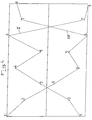
- the method according to the invention consists in determining in particular, for each heartbeat, from curves C1, C2 and C3 corresponding respectively to the signal I representing the variation of the impedance of a volume V defined from the body 6 of a patient, to the time derivative dI / dt of the signal previous, and to the time derivative of the signal EKG, HR heart rate, flow QC heart, WC heart work and blood pressure average PAM, systolic PAS and diastolic PAD.
- This constant K is determined for each patient and his value is communicated to digital preprocessing unit 7 at during initialization operations.
- HR heart rate expressed in beats / minute is preferably extracted from the derivative of the signal electrocardiographic, therefore of the curve C3, thus making it possible to get rid of interference often affecting the signal electrocardiographic ( Figure 3C).
- the present invention advantageously uses this surprising feature for determining the pressure mean arterial PAM.
- RV1, RV2, IC1 and IC2 chosen, if applicable automatically necessary during initialization operations, being those which best verify the aforementioned rule of symmetry.
- the value of the body surface area SC in cm 2 given by the formula [Size (in cm) + Weight (in kg) - 60] / 100 , will also be stored, for each patient, as a constant.
- the polynomial function F (X, Y) preferably having a formulation of the type: F (X,
- the values of the constants A, B, C, D, G, I, J, K and L can be calculated by carrying out a large number of successive examinations during which it will be making the determination, so separate, RV, PAD, and WC values.
- these different constants may have the following values: A ⁇ 0.0035, B ⁇ 2150, C ⁇ 1.8, D ⁇ 4.5, G ⁇ 6.4, I ⁇ 41, J ⁇ 165, K ⁇ 2140 and L ⁇ 128.
- the dimensional dimension of BO axis / bO axis is, in the opinion of the inventors, correlated with the atrial ejected volume ratio telediastolic / telediastolic ventricular volume and represents therefore a close index of ventricular compliance left.
- the arrangement described above makes it possible to overcome, during the initialization phase, the realization of a measurement of RV and IC parameters in particular, for a patient's state of exertion and authorizes the implementation of said process by risk customers, bedridden, etc.
- the process can also consist in transmitting, during operations test signals at the electrodes transmitters 2, in order to determine in particular, by scanning frequency, the transmission frequency enabling the signal to be obtained sharper on reception at the 2 'receiving electrodes.
- the transmission frequency for the impedance variation measurements is set digitally, in function of a comparative analysis of the signals recovered at the level 2 'receiving antennas for different transmission signals from different frequencies.
- the method according to the invention consists in carrying out, after processing, a check of the digitized signals and values parameters determined for each heartbeat, and eliminate signals and parameters with values located outside a predetermined range, fixed during operations initialization.
- said device can advantageously calculate and display the values of FC, QC, WC, RV, IC, FE, PAM, PAS and PAD parameters in averaging over ten consecutive heartbeats.
- the apparatus and the method according to the invention allow to indicate permanently, continuously and in real time, the patient's blood pressure, synchronized with the signal ECG, a hemodynamic signal and various signals from additional sensors.
Landscapes
- Health & Medical Sciences (AREA)
- Life Sciences & Earth Sciences (AREA)
- Molecular Biology (AREA)
- Surgery (AREA)
- Physics & Mathematics (AREA)
- Veterinary Medicine (AREA)
- Biophysics (AREA)
- Pathology (AREA)
- Engineering & Computer Science (AREA)
- Biomedical Technology (AREA)
- Heart & Thoracic Surgery (AREA)
- Animal Behavior & Ethology (AREA)
- Public Health (AREA)
- General Health & Medical Sciences (AREA)
- Medical Informatics (AREA)
- Hematology (AREA)
- Radiology & Medical Imaging (AREA)
- Nuclear Medicine, Radiotherapy & Molecular Imaging (AREA)
- Cardiology (AREA)
- Measurement And Recording Of Electrical Phenomena And Electrical Characteristics Of The Living Body (AREA)
- Measuring Pulse, Heart Rate, Blood Pressure Or Blood Flow (AREA)
- Investigating Or Analysing Biological Materials (AREA)
- Measuring And Recording Apparatus For Diagnosis (AREA)
- Electrotherapy Devices (AREA)
Claims (25)
- Vorrichtung zur Erfassung, Messung und Verarbeitung physiologischer Signale zur Bestimmung von Herz- und Kreislaufparametern, dadurch gekennzeichnet, daß sie einerseits Mittel (3, 3', 4, 4' und 5) zur Erfassung, Formung und Digitalisierung eines elektrokardiographischen Signals und eines die Impedanzveränderung eines bestimmten Volumens (V) des Körpers (6) eines Patienten darstellenden Signals in Form integrierter Schaltkreise, die mit Elektroden (1, 2, 2') verbunden sind, welche an spezifischen Stellen dieses Körpers angeordnet sind, andererseits eine Einheit (7) zur digitalen Vorverarbeitung, die mit Steuer- (8) und Anzeigemitteln (9) zusammenarbeitet, und ein abnehmbares Speichermittel (10) und/oder ein Mittel (11) zur Übertragung der Gesamtheit der digitalisierten Signale oder von aus diesen digitalisierten Signalen entnommenen Werten signifikanter Parameter (FC, QC, WC, RV, IC, FE, PAM, PAS und PAD) für jeden Herzschlag, und schließlich eine zentrale Vorrichtung (12) zur digitalen Verarbeitung aufweist, die durch aufeinanderfolgende Übertragungen die vom Speichermittel (10) oder vom Übertragungsmittel (11) kommenden Daten empfängt und speichert und die Analyse dieser Daten oder dieser Parameter über große Zeiträume, ihren Vergleich mit früheren Daten oder Parameterwerten und die Anzeige und/oder den Ausdruck der Gesamtheit der Daten ermöglicht, die zur Ausarbeitung einer Diagnose dienen können, wobei die Erfassungsmittel (3, 3', 4, 4' und 5) in einem ersten Gehäuse angeordnet sind, das mit den Elektroden (1, 2, 2') verbunden ist, und daß die Vorverarbeitungseinheit (7) und die Steuer- und Anzeigemittel (8 und 9) und die Speichermittel (10) und/oder das Übertragungsmittel (11) in einem zweiten Gehäuse zusammengefaßt sind, das ggf. am Handgelenk des Patienten befestigt ist, Vorrichtung, die außerdem eine zentrale Vorrichtung (12) zur digitalen Verarbeitung aufweist, wobei die Verbindung zwischen den beiden erwähnten Gehäusen eine Drahtverbindung oder eine Funkverbindung ist.
- Vorrichtung nach Anspruch 1, dadurch gekennzeichnet, daß sie ein synchrones Erfassungsmittel (3') zur Erfassung des die Impedanzveränderung darstellenden Signals aufweist, das einen Schwachstrom mit einstellbarer, hoher Frequenz erzeugt, der durch ein definiertes, kegelstumpfförmiges Volumen (V) des Rumpfes eines Patienten und zwischen einer Einheit von Sendeelektroden (2) und einer Einheit von Empfangselektroden (2') fließt, deren Standorte das Volumen (V) begrenzen.
- Vorrichtung nach Anspruch 2, dadurch gekennzeichnet, daß die Sende- und Meßfrequenz des synchronen Erfassungsmittels (3') auf einen für einen gegebenen Patienten optimalen Wert digital einstellbar ist und daß die Verstärkungen der Signal-Verstärkungsmittel (14, 21), die Teil der Mittel (4') zur Formung des Signals der Impedanzveränderung und/oder der synchronen Erfassungsvorrichtung (3') sind, ebenfalls digital einstellbar sind, zum Beispiel durch die zentrale Vorrichtung (12) während einer Initialisierungsphase.
- Vorrichtung nach einem beliebigen der Ansprüche 1 bis 3, dadurch gekennzeichnet, daß sie einen Schnittstellenmodul (7'') aufweist, der mit Analog/Digital-Wandler- und Abtast-Schaltkreisen versehen ist und es ermöglicht, der Verarbeitungseinheit (7) in digitaler Form verschiedene Signale zu liefern, die von zusätzlichen, am Patienten befestigten Meßsonden abgegeben werden.
- Vorrichtung nach Anspruch 1, dadurch gekennzeichnet, daß sie zur Messung der Impedanzveränderung zwei Sendeelektroden (2) und zwei Empfangselektroden (2') aufweist, wobei ein erstes Paar von Sende-/Empfangselektroden (2, 2') dazu bestimmt ist, auf die Haut des Patienten in Höhe des obersten Teils des Brustbeins aufgelegt zu werden, und das andere Paar von Elektroden (2, 2'), das dem ersten Paar zugeordnet oder dazu komplementär ist, in Höhe des Schwertfortsatzes angelegt wird.
- Vorrichtung nach Anspruch 5, dadurch gekennzeichnet, daß die beiden Elektrodenpaare (2, 2') auf einem Hauptträger (30) bzw. einem Nebenträger (31) länglicher Form angeordnet sind, die in Bezug aufeinander gleiten können, um die beiden Elektrodenpaare (2, 2') voneinander zu entfernen oder einander anzunähern, wobei der Abstand zwischen den beiden Empfangselektroden (2') visuell mittels einer Gradeinteilung bestimmt werden kann.
- Vorrichtung nach Anspruch 6, dadurch gekennzeichnet, daß der Hauptträger (30) in Form eines Rohrs vorliegt und zusätzlich zu einem Elektrodenpaar (2, 2') zwei Elektroden (1) zur Erfassung des Elektrokardiogramms und ein Befestigungsmittel (32) aufweist, und daß der Nebenträger (31) in Form einer mit Gradeinteilung versehenen Leiste oder Lasche vorliegt, die in Bezug auf den Hauptträger (30) teleskopisch gleiten kann und an ihrem freien Ende ein Elektrodenpaar (2, 2') trägt, wobei die Übertragung zwischen den Elektroden (1, 2 und 2') und den Erfassungsmitteln (3, 3') über eine Drahtverbindung oder über Infrarotwellen erfolgen kann.
- Vorrichtung nach Anspruch 1, dadurch gekennzeichnet, daß eine Vorrichtung zur optischen Isolierung (22) zwischen den Erfassungsmitteln (3, 3') und den Formungsmitteln (4, 4') der Signale einerseits und den Digitalisierungsmitteln (5) der Signale andererseits angeordnet ist.
- Automatisches Verfahren zur Messung und zur Verarbeitung physiologischer Signale zur Bestimmung von Herz- und Kreislaufparametern, das nach verschiedenen Initialisierungsvorgängen darin besteht, mittels Elektroden (1, 2, 2') mindestens ein elektrokardiographisches Signal und ein die Impedanzveränderung eines bestimmten, von Sendeelektroden (2) und Empfangselektroden (2') begrenzten Volumens (V) des Körpers (6) eines Patienten darstellendes Signal kontinuierlich zu erfassen, diese Signale zu filtern und zu digitalisieren und sie dann zu verarbeiten, dadurch gekennzeichnet, daß es darin besteht, für jeden Herzschlag ausgehend von Kurven (C1, C2, C3), die dem Signal I, das die Impedanzveränderung eines definierten Volumens (V) des Körpers (6) eines Patienten darstellt, bzw. der zeitlichen Ableitung des vorhergehenden Signals bzw. der zeitlichen Ableitung des elektrokardiographischen Signals entsprechen, die Herzfrequenz (FC), die Herzleistung (QC), die Herztätigkeit (WC) und die mittleren (PAM), systolischen (PAD) und diastolischen Arteriendrücke (PAD) zu bestimmen, in Echtzeit den Wert oder die Werte eines oder mehrerer dieser Parameter anzuzeigen, die Gesamtheit der digitalisierten Signale durchgehend zu speichern und schließlich die gespeicherten Daten zu übertragen und zu tasten,
- Verfahren nach Anspruch 9, dadurch gekennzeichnet, daß es darin besteht, für jeden Herzschlag den Wert des Verhältnisses
- Verfahren nach Anspruch 9, dadurch gekennzeichnet, daß das von den Elektroden (2, 2') begrenzte Volumen (V) aus einem Kegelstumpf besteht, dessen kleine Basis (b) sich am Hals des Patienten und dessen große Basis (B) sich in Höhe der Taille des Patienten befindet, was es ermöglicht, eine Konstante (K) zu definieren, derart, daß :
- H
- = Höhe des Kegelstumpfs in cm,
- D
- = Durchmesser der großen Basis in cm,
- d
- = Durchmesser der kleinen Basis in cm.
- Verfahren nach Anspruch 9, dadurch gekennzeichnet, daß das für die Messung der Impedanzveränderung berücksichtigte Volumen (V) aus einem Kegelstumpf besteht, der sich zwischen dem Hals und dem Brustkorb im schalenförmigen Bereich befindet, was es ermöglicht, eine Konstante (K) zu bestimmen, derart, daß:
- H
- = Abstand zwischen den beiden Empfangselektroden 2',
- C
- = Umfang des Brustkorbs im schalenförmigen Bereich,
- c
- = Umfang des Halses.
- Verfahren nach Anspruch 9, dadurch gekennzeichnet, daß es darin besteht, das ausgestoßene systolische Volumen (VES) und die Herzleistung (QC) durch die folgenden Formeln zu bestimmen:
- Verfahren nach Anspruch 9, dadurch gekennzeichnet, daß es darin besteht, ausgehend vom für jeden Herzschlag berechneten Verhältnis (IC), den indexierten peripheren Widerstand (RV) mittels der folgenden Formel zu bestimmen:wobei (RV1) und RV2) bzw. (IC1) und (IC2) Werte von (RV) bzw. (IC) darstellen, die manuell für zwei unterschiedliche Zustände des Patienten bestimmt und bei den Initialisierungsvorgängen gespeichert werden.
- Verfahren nach Anspruch 9, dadurch gekennzeichnet, daß der mittlere Arteriendruck (PAM) für jeden Herzschlag mittels der folgenden Formel berechnet wird:wobei (QC) die Herzleistung, (RV) den indexierten peripheren Widerstand und (SC) die Körperoberflache des Patienten darstellt, die dem Verfahren unterworfen wird, wobei der Wert der Herztätigkeit (WC) dann durch die folgende Formel bestimmt wird:
- Verfahren nach Anspruch 15, dadurch gekennzeichnet, daß der diastolische Arteriendruck (PAD) für jeden Herzschlag mittels einer polynominalen Funktion bestimmt wird, derart, daß:mitwobei A, B, C und D Konstante darstellen.
- Verfahren nach Anspruch 16, dadurch gekennzeichnet, daß die polynominale Funktion F(X, Y) eine Formulierung der Artwobei G, I, J, K und L Konstante sind.
- Verfahren nach den Ansprüchen 14 und 15, dadurch gekennzeichnet, daß es darin besteht, den Ausstoßanteil (FE) mittels der Formelwobeimitund
- Verfahren nach Anspruch 10, dadurch gekennzeichnet, daß es darin besteht, digital für jeden Herzschlag eine Kurve (C4) zu erstellen, die die Funktion
- Verfahren nach Anspruch 9, dadurch gekennzeichnet, daß es darin besteht, für jeden Herzschlag und ausgehend von bestimmten digitalen Werten für die Kurven (C1 und C2) digital eine Kurve (C5) zu erstellen, die die Funktion
- Verfahren nach Anspruch 9, dadurch gekennzeichnet, daß es darin besteht, einen Koeffizienten
- Verfahren nach Anspruch 9, dadurch gekennzeichnet, daß es darin besteht, während der Initialisierungsvorgänge Testsignale in Höhe der Sendeelektroden (2) auszugeben, um insbesondere durch Frequenzabtastung die Sendefrequenz zu bestimmen, die es ermöglicht, das klarste Signal beim Empfang in Höhe der Empfangselektroden (2') zu erhalten.
- Verfahren nach Anspruch 22, dadurch gekennzeichnet, daß die Sendefrequenz für die Messungen von Impedanzveränderung in Abhängigkeit von einer vergleichenden Analyse der aufgefangenen Signale in Höhe der Empfangsantennen (2') für verschiedene Sendesignale verschiedener Frequenzen digital eingestellt wird.
- Verfahren nach Anspruch 9, dadurch gekennzeichnet, daß es darin besteht, nach der Verarbeitung eine Kontrolle der digitalisierten Signale und der Werte der bestimmten Parameter für jeden Herzschlag durchzuführen und die Signale und die Parameter zu entfernen, die Werte aufweisen, welche sich außerhalb eines vorbestimmten Bereichs befinden, der bei den Initialisierungsvorgängen festgelegt wurde.
- Verfahren nach Anspruch 9, dadurch gekennzeichnet, daß es darin besteht, die Werte der Parameter (FC, QC, WC, FE, PAM, PAS und PAD) zu berechnen und anzuzeigen, indem Mittelwerte von zehn aufeinanderfolgenden Herzschlägen erstellt werden.
Applications Claiming Priority (3)
| Application Number | Priority Date | Filing Date | Title |
|---|---|---|---|
| FR9309262 | 1993-07-23 | ||
| FR9309262A FR2707860B1 (fr) | 1993-07-23 | 1993-07-23 | Appareil de mesure et de traitement de signaux physiologiques et procédé automatique mis en Óoeuvre par ledit appareil. |
| PCT/FR1994/000930 WO1995002991A1 (fr) | 1993-07-23 | 1994-07-25 | Appareil de mesure et de traitement de signaux physiologiques et procede automatique mis en ×uvre par ledit appareil |
Publications (2)
| Publication Number | Publication Date |
|---|---|
| EP0710086A1 EP0710086A1 (de) | 1996-05-08 |
| EP0710086B1 true EP0710086B1 (de) | 1999-09-08 |
Family
ID=9449694
Family Applications (1)
| Application Number | Title | Priority Date | Filing Date |
|---|---|---|---|
| EP94922303A Expired - Lifetime EP0710086B1 (de) | 1993-07-23 | 1994-07-25 | Vorrichtung und verfahren zum messen und verarbeiten von physiologischen signalen |
Country Status (9)
| Country | Link |
|---|---|
| US (1) | US5735286A (de) |
| EP (1) | EP0710086B1 (de) |
| JP (1) | JPH09500555A (de) |
| AT (1) | ATE184172T1 (de) |
| AU (1) | AU7347194A (de) |
| DE (1) | DE69420566T2 (de) |
| ES (1) | ES2139085T3 (de) |
| FR (1) | FR2707860B1 (de) |
| WO (1) | WO1995002991A1 (de) |
Families Citing this family (15)
| Publication number | Priority date | Publication date | Assignee | Title |
|---|---|---|---|---|
| US6256643B1 (en) * | 1998-03-10 | 2001-07-03 | Baxter International Inc. | Systems and methods for storing, retrieving, and manipulating data in medical processing devices |
| DE19638738B4 (de) * | 1996-09-10 | 2006-10-05 | Bundesrepublik Deutschland, vertr. d. d. Bundesministerium für Wirtschaft und Technologie, dieses vertr. d. d. Präsidenten der Physikalisch-Technischen Bundesanstalt | Verfahren zur Gewinnung einer diagnostischen Aussage aus Signalen und Daten medizinischer Sensorsysteme |
| US6285909B1 (en) | 1999-05-27 | 2001-09-04 | Cardiac Pacemakers, Inc. | Preserving patient specific data in implantable pulse generator systems |
| US6506162B1 (en) * | 2000-06-09 | 2003-01-14 | K-Jump Health Co., Ltd. | Electronic blood pressure gauge equipped with dismountable external memory device |
| US6534693B2 (en) * | 2000-11-06 | 2003-03-18 | Afmedica, Inc. | Surgically implanted devices having reduced scar tissue formation |
| SE0004417D0 (sv) * | 2000-11-28 | 2000-11-28 | St Jude Medical | Implantable device |
| DE10116361A1 (de) * | 2001-04-02 | 2002-10-10 | Heptec Gmbh | Funkmodul, Respirator, Überwachungsgerät dafür; Therapiegerät zur Durchführung der CPAP-Therapie, Überwachungsgerät dafür; Systeme sowie Verfahren |
| US6731973B2 (en) | 2001-06-12 | 2004-05-04 | Ge Medical Systems Information Technologies, Inc. | Method and apparatus for processing physiological data |
| SE0202290D0 (sv) * | 2002-07-22 | 2002-07-22 | St Jude Medical | Monitor |
| US20050079508A1 (en) * | 2003-10-10 | 2005-04-14 | Judy Dering | Constraints-based analysis of gene expression data |
| US20050288585A1 (en) * | 2004-06-24 | 2005-12-29 | Siemens Medical Solutions Usa, Inc. | Flexible physiological cycle detection and use for ultrasound |
| US7630763B2 (en) | 2005-04-20 | 2009-12-08 | Cardiac Pacemakers, Inc. | Thoracic or intracardiac impedance detection with automatic vector selection |
| US9839781B2 (en) | 2005-08-22 | 2017-12-12 | Cardiac Pacemakers, Inc. | Intracardiac impedance and its applications |
| CZ306759B6 (cs) | 2008-08-05 | 2017-06-21 | Univerzita Karlova v Praze, Lékařská fakulta v Plzni | Diagnostický systém pro zjištování a sledování bioimpedance hrudníku a stanovení emergentních stavů hrudníku |
| FR2940039B1 (fr) * | 2008-12-19 | 2011-11-25 | Ass Enseignement Tech Superieur Groupe Esaip | Procede de mesure d'un indice de la rigidite locale de la paroi d'une artere de conduction et installation correspondante |
Family Cites Families (5)
| Publication number | Priority date | Publication date | Assignee | Title |
|---|---|---|---|---|
| US4562843A (en) * | 1980-09-29 | 1986-01-07 | Ljubomir Djordjevich | System for determining characteristics of blood flow |
| CN1024161C (zh) * | 1987-09-05 | 1994-04-13 | 哈尔滨工业大学 | 检测和处理阻抗血流图的方法及装置 |
| US4807638A (en) * | 1987-10-21 | 1989-02-28 | Bomed Medical Manufacturing, Ltd. | Noninvasive continuous mean arterial blood prssure monitor |
| US5309917A (en) * | 1991-09-12 | 1994-05-10 | Drexel University | System and method of impedance cardiography and heartbeat determination |
| US5584298A (en) * | 1993-10-25 | 1996-12-17 | Kabal; John | Noninvasive hemodynamic analyzer alterable to a continuous invasive hemodynamic monitor |
-
1993
- 1993-07-23 FR FR9309262A patent/FR2707860B1/fr not_active Expired - Fee Related
-
1994
- 1994-07-25 JP JP7504987A patent/JPH09500555A/ja active Pending
- 1994-07-25 WO PCT/FR1994/000930 patent/WO1995002991A1/fr not_active Ceased
- 1994-07-25 AU AU73471/94A patent/AU7347194A/en not_active Abandoned
- 1994-07-25 AT AT94922303T patent/ATE184172T1/de not_active IP Right Cessation
- 1994-07-25 ES ES94922303T patent/ES2139085T3/es not_active Expired - Lifetime
- 1994-07-25 DE DE69420566T patent/DE69420566T2/de not_active Expired - Fee Related
- 1994-07-25 EP EP94922303A patent/EP0710086B1/de not_active Expired - Lifetime
- 1994-07-25 US US08/586,920 patent/US5735286A/en not_active Expired - Lifetime
Also Published As
| Publication number | Publication date |
|---|---|
| DE69420566T2 (de) | 2000-03-30 |
| DE69420566D1 (de) | 1999-10-14 |
| AU7347194A (en) | 1995-02-20 |
| FR2707860B1 (fr) | 1995-09-08 |
| EP0710086A1 (de) | 1996-05-08 |
| US5735286A (en) | 1998-04-07 |
| WO1995002991A1 (fr) | 1995-02-02 |
| ES2139085T3 (es) | 2000-02-01 |
| JPH09500555A (ja) | 1997-01-21 |
| FR2707860A1 (fr) | 1995-01-27 |
| ATE184172T1 (de) | 1999-09-15 |
Similar Documents
| Publication | Publication Date | Title |
|---|---|---|
| EP0710086B1 (de) | Vorrichtung und verfahren zum messen und verarbeiten von physiologischen signalen | |
| US10709339B1 (en) | Biometric wearable for continuous heart rate and blood pressure monitoring | |
| CN105877723B (zh) | 无创连续血压测量装置 | |
| US9649042B2 (en) | Heart monitoring system usable with a smartphone or computer | |
| KR101560287B1 (ko) | 생체신호 측정 수단을 포함하는 이어폰 및 이러한 이어폰을 포함하는 생체신호 모니터링 시스템 | |
| CA2816894C (en) | Wireless fetal monitoring system | |
| US9492138B2 (en) | Mobile front-end system for comprehensive cardiac diagnosis | |
| US8301232B2 (en) | Wireless, ultrasonic personal health monitoring system | |
| EP3110321B1 (de) | Verfahren, vorrichtung, system und computerprogramm zur filterung einer aus einem herzsignal abgeleiteten rr-serie mit automatischer qualitätskontrolle der rr-serie | |
| CN111558148B (zh) | 颈部按摩仪的健康检测方法及颈部按摩仪 | |
| CN205866733U (zh) | 无创连续血压测量装置 | |
| US11051765B2 (en) | Health status detecting system and method for detecting health status | |
| EP1513444B1 (de) | Frequenzverarbeitung einer rr-serie eines analogen herzsignals | |
| US12303240B2 (en) | Non-invasive non-compressive blood pressure monitoring device | |
| EP0681447B1 (de) | Vorrichtung zur bestimmung von physiologischen daten sowie verwendung der vorrichtung | |
| EP1804655A1 (de) | Verfahren zur verarbeitung einer reihe von herzrhythmussignalen (rr) und seine verwendung bei der analyse einer herzrhythmusvariabilität, insbesondere zur beurteilung von schmerz oder stress eines patienten | |
| CN118302105A (zh) | 用于进行生物阻抗的复数测量的生理传感器贴片 | |
| CA2167193C (fr) | Appareil de mesure et de traitement de signaux physiologiques et procede automatique mis en oeuvre par ledit appareil | |
| FR2535964A1 (fr) | Appareillage de mesure, de traitement, de stockage et d'affichage de signaux biomedicaux | |
| TW201634004A (zh) | 穿戴式複合血管流速偵測器 | |
| EP3110322B1 (de) | Verfahren und vorrichtung zur automatischen überprüfung der qualität einer aus einem herzsignal ermittelten rr-intervallserie | |
| WO2025200378A1 (zh) | 一种可穿戴式心脏超声成像贴片系统及成像方法 | |
| WO2020165758A1 (en) | Device and method for cardiopathies assessment | |
| CN202636934U (zh) | 小型阵发性室上性心动过速检测装置 | |
| FR2853518A1 (fr) | Dispositif de surveillance a distance des parametres physiologiques d'un individu |
Legal Events
| Date | Code | Title | Description |
|---|---|---|---|
| PUAI | Public reference made under article 153(3) epc to a published international application that has entered the european phase |
Free format text: ORIGINAL CODE: 0009012 |
|
| 17P | Request for examination filed |
Effective date: 19960222 |
|
| AK | Designated contracting states |
Kind code of ref document: A1 Designated state(s): AT BE CH DE DK ES FR GB GR IE IT LI LU MC NL PT SE |
|
| 17Q | First examination report despatched |
Effective date: 19960607 |
|
| GRAG | Despatch of communication of intention to grant |
Free format text: ORIGINAL CODE: EPIDOS AGRA |
|
| GRAG | Despatch of communication of intention to grant |
Free format text: ORIGINAL CODE: EPIDOS AGRA |
|
| GRAH | Despatch of communication of intention to grant a patent |
Free format text: ORIGINAL CODE: EPIDOS IGRA |
|
| GRAH | Despatch of communication of intention to grant a patent |
Free format text: ORIGINAL CODE: EPIDOS IGRA |
|
| GRAA | (expected) grant |
Free format text: ORIGINAL CODE: 0009210 |
|
| AK | Designated contracting states |
Kind code of ref document: B1 Designated state(s): AT BE CH DE DK ES FR GB GR IE IT LI LU MC NL PT SE |
|
| PG25 | Lapsed in a contracting state [announced via postgrant information from national office to epo] |
Ref country code: SE Free format text: THE PATENT HAS BEEN ANNULLED BY A DECISION OF A NATIONAL AUTHORITY Effective date: 19990908 Ref country code: NL Free format text: LAPSE BECAUSE OF FAILURE TO SUBMIT A TRANSLATION OF THE DESCRIPTION OR TO PAY THE FEE WITHIN THE PRESCRIBED TIME-LIMIT Effective date: 19990908 Ref country code: GR Free format text: LAPSE BECAUSE OF NON-PAYMENT OF DUE FEES Effective date: 19990908 Ref country code: AT Free format text: LAPSE BECAUSE OF FAILURE TO SUBMIT A TRANSLATION OF THE DESCRIPTION OR TO PAY THE FEE WITHIN THE PRESCRIBED TIME-LIMIT Effective date: 19990908 |
|
| REF | Corresponds to: |
Ref document number: 184172 Country of ref document: AT Date of ref document: 19990915 Kind code of ref document: T |
|
| REG | Reference to a national code |
Ref country code: CH Ref legal event code: EP |
|
| REF | Corresponds to: |
Ref document number: 69420566 Country of ref document: DE Date of ref document: 19991014 |
|
| REG | Reference to a national code |
Ref country code: IE Ref legal event code: FG4D Free format text: FRENCH |
|
| ITF | It: translation for a ep patent filed | ||
| PG25 | Lapsed in a contracting state [announced via postgrant information from national office to epo] |
Ref country code: DK Free format text: LAPSE BECAUSE OF FAILURE TO SUBMIT A TRANSLATION OF THE DESCRIPTION OR TO PAY THE FEE WITHIN THE PRESCRIBED TIME-LIMIT Effective date: 19991208 |
|
| PG25 | Lapsed in a contracting state [announced via postgrant information from national office to epo] |
Ref country code: PT Free format text: LAPSE BECAUSE OF FAILURE TO SUBMIT A TRANSLATION OF THE DESCRIPTION OR TO PAY THE FEE WITHIN THE PRESCRIBED TIME-LIMIT Effective date: 19991209 |
|
| GBT | Gb: translation of ep patent filed (gb section 77(6)(a)/1977) |
Effective date: 19991209 |
|
| NLV1 | Nl: lapsed or annulled due to failure to fulfill the requirements of art. 29p and 29m of the patents act | ||
| REG | Reference to a national code |
Ref country code: ES Ref legal event code: FG2A Ref document number: 2139085 Country of ref document: ES Kind code of ref document: T3 |
|
| PG25 | Lapsed in a contracting state [announced via postgrant information from national office to epo] |
Ref country code: IE Free format text: LAPSE BECAUSE OF NON-PAYMENT OF DUE FEES Effective date: 20000621 |
|
| PLBE | No opposition filed within time limit |
Free format text: ORIGINAL CODE: 0009261 |
|
| STAA | Information on the status of an ep patent application or granted ep patent |
Free format text: STATUS: NO OPPOSITION FILED WITHIN TIME LIMIT |
|
| REG | Reference to a national code |
Ref country code: IE Ref legal event code: FD4D |
|
| PG25 | Lapsed in a contracting state [announced via postgrant information from national office to epo] |
Ref country code: LU Free format text: LAPSE BECAUSE OF NON-PAYMENT OF DUE FEES Effective date: 20000725 |
|
| PG25 | Lapsed in a contracting state [announced via postgrant information from national office to epo] |
Ref country code: MC Free format text: THE PATENT HAS BEEN ANNULLED BY A DECISION OF A NATIONAL AUTHORITY Effective date: 20000731 Ref country code: LI Free format text: LAPSE BECAUSE OF NON-PAYMENT OF DUE FEES Effective date: 20000731 Ref country code: CH Free format text: LAPSE BECAUSE OF NON-PAYMENT OF DUE FEES Effective date: 20000731 Ref country code: BE Free format text: LAPSE BECAUSE OF NON-PAYMENT OF DUE FEES Effective date: 20000731 |
|
| 26N | No opposition filed | ||
| BERE | Be: lapsed |
Owner name: BOUR FRANK Effective date: 20000731 Owner name: BOUR JEAN Effective date: 20000731 |
|
| REG | Reference to a national code |
Ref country code: CH Ref legal event code: PL |
|
| REG | Reference to a national code |
Ref country code: GB Ref legal event code: IF02 |
|
| PGFP | Annual fee paid to national office [announced via postgrant information from national office to epo] |
Ref country code: FR Payment date: 20020930 Year of fee payment: 9 |
|
| PG25 | Lapsed in a contracting state [announced via postgrant information from national office to epo] |
Ref country code: FR Free format text: LAPSE BECAUSE OF NON-PAYMENT OF DUE FEES Effective date: 20030331 |
|
| REG | Reference to a national code |
Ref country code: FR Ref legal event code: ST |
|
| PGFP | Annual fee paid to national office [announced via postgrant information from national office to epo] |
Ref country code: ES Payment date: 20040818 Year of fee payment: 11 |
|
| PG25 | Lapsed in a contracting state [announced via postgrant information from national office to epo] |
Ref country code: ES Free format text: LAPSE BECAUSE OF NON-PAYMENT OF DUE FEES Effective date: 20050726 |
|
| REG | Reference to a national code |
Ref country code: ES Ref legal event code: FD2A Effective date: 20050726 |
|
| PGFP | Annual fee paid to national office [announced via postgrant information from national office to epo] |
Ref country code: GB Payment date: 20090730 Year of fee payment: 16 Ref country code: DE Payment date: 20090811 Year of fee payment: 16 |
|
| PGFP | Annual fee paid to national office [announced via postgrant information from national office to epo] |
Ref country code: IT Payment date: 20090731 Year of fee payment: 16 |
|
| GBPC | Gb: european patent ceased through non-payment of renewal fee |
Effective date: 20100725 |
|
| PG25 | Lapsed in a contracting state [announced via postgrant information from national office to epo] |
Ref country code: DE Free format text: LAPSE BECAUSE OF NON-PAYMENT OF DUE FEES Effective date: 20110201 |
|
| REG | Reference to a national code |
Ref country code: DE Ref legal event code: R119 Ref document number: 69420566 Country of ref document: DE Effective date: 20110201 |
|
| PG25 | Lapsed in a contracting state [announced via postgrant information from national office to epo] |
Ref country code: IT Free format text: LAPSE BECAUSE OF NON-PAYMENT OF DUE FEES Effective date: 20100725 |
|
| PG25 | Lapsed in a contracting state [announced via postgrant information from national office to epo] |
Ref country code: GB Free format text: LAPSE BECAUSE OF NON-PAYMENT OF DUE FEES Effective date: 20100725 |