EP0710520A2 - Mandrin porte-foret - Google Patents
Mandrin porte-foret Download PDFInfo
- Publication number
- EP0710520A2 EP0710520A2 EP95105407A EP95105407A EP0710520A2 EP 0710520 A2 EP0710520 A2 EP 0710520A2 EP 95105407 A EP95105407 A EP 95105407A EP 95105407 A EP95105407 A EP 95105407A EP 0710520 A2 EP0710520 A2 EP 0710520A2
- Authority
- EP
- European Patent Office
- Prior art keywords
- locking
- clamping
- ring
- clamping ring
- chuck
- Prior art date
- Legal status (The legal status is an assumption and is not a legal conclusion. Google has not performed a legal analysis and makes no representation as to the accuracy of the status listed.)
- Granted
Links
Images


Classifications
-
- B—PERFORMING OPERATIONS; TRANSPORTING
- B23—MACHINE TOOLS; METAL-WORKING NOT OTHERWISE PROVIDED FOR
- B23B—TURNING; BORING
- B23B31/00—Chucks; Expansion mandrels; Adaptations thereof for remote control
- B23B31/02—Chucks
- B23B31/10—Chucks characterised by the retaining or gripping devices or their immediate operating means
- B23B31/12—Chucks with simultaneously-acting jaws, whether or not also individually adjustable
- B23B31/1207—Chucks with simultaneously-acting jaws, whether or not also individually adjustable moving obliquely to the axis of the chuck in a plane containing this axis
- B23B31/1238—Jaws movement actuated by a nut with conical screw-thread
-
- B—PERFORMING OPERATIONS; TRANSPORTING
- B23—MACHINE TOOLS; METAL-WORKING NOT OTHERWISE PROVIDED FOR
- B23B—TURNING; BORING
- B23B31/00—Chucks; Expansion mandrels; Adaptations thereof for remote control
- B23B31/02—Chucks
- B23B31/10—Chucks characterised by the retaining or gripping devices or their immediate operating means
- B23B31/12—Chucks with simultaneously-acting jaws, whether or not also individually adjustable
- B23B31/1207—Chucks with simultaneously-acting jaws, whether or not also individually adjustable moving obliquely to the axis of the chuck in a plane containing this axis
- B23B31/1215—Details of the jaws
-
- B—PERFORMING OPERATIONS; TRANSPORTING
- B23—MACHINE TOOLS; METAL-WORKING NOT OTHERWISE PROVIDED FOR
- B23B—TURNING; BORING
- B23B31/00—Chucks; Expansion mandrels; Adaptations thereof for remote control
- B23B31/02—Chucks
- B23B31/10—Chucks characterised by the retaining or gripping devices or their immediate operating means
- B23B31/12—Chucks with simultaneously-acting jaws, whether or not also individually adjustable
- B23B31/1207—Chucks with simultaneously-acting jaws, whether or not also individually adjustable moving obliquely to the axis of the chuck in a plane containing this axis
- B23B31/123—Chucks with simultaneously-acting jaws, whether or not also individually adjustable moving obliquely to the axis of the chuck in a plane containing this axis with locking arrangements
-
- B—PERFORMING OPERATIONS; TRANSPORTING
- B23—MACHINE TOOLS; METAL-WORKING NOT OTHERWISE PROVIDED FOR
- B23B—TURNING; BORING
- B23B2231/00—Details of chucks, toolholder shanks or tool shanks
- B23B2231/38—Keyless chucks for hand tools
-
- B—PERFORMING OPERATIONS; TRANSPORTING
- B23—MACHINE TOOLS; METAL-WORKING NOT OTHERWISE PROVIDED FOR
- B23B—TURNING; BORING
- B23B2231/00—Details of chucks, toolholder shanks or tool shanks
- B23B2231/44—Nose pieces
-
- Y—GENERAL TAGGING OF NEW TECHNOLOGICAL DEVELOPMENTS; GENERAL TAGGING OF CROSS-SECTIONAL TECHNOLOGIES SPANNING OVER SEVERAL SECTIONS OF THE IPC; TECHNICAL SUBJECTS COVERED BY FORMER USPC CROSS-REFERENCE ART COLLECTIONS [XRACs] AND DIGESTS
- Y10—TECHNICAL SUBJECTS COVERED BY FORMER USPC
- Y10S—TECHNICAL SUBJECTS COVERED BY FORMER USPC CROSS-REFERENCE ART COLLECTIONS [XRACs] AND DIGESTS
- Y10S279/00—Chucks or sockets
- Y10S279/902—Keyless type socket
-
- Y—GENERAL TAGGING OF NEW TECHNOLOGICAL DEVELOPMENTS; GENERAL TAGGING OF CROSS-SECTIONAL TECHNOLOGIES SPANNING OVER SEVERAL SECTIONS OF THE IPC; TECHNICAL SUBJECTS COVERED BY FORMER USPC CROSS-REFERENCE ART COLLECTIONS [XRACs] AND DIGESTS
- Y10—TECHNICAL SUBJECTS COVERED BY FORMER USPC
- Y10T—TECHNICAL SUBJECTS COVERED BY FORMER US CLASSIFICATION
- Y10T279/00—Chucks or sockets
- Y10T279/17—Socket type
- Y10T279/17615—Obliquely guided reciprocating jaws
- Y10T279/17623—Threaded sleeve and jaw
- Y10T279/17632—Conical sleeve
-
- Y—GENERAL TAGGING OF NEW TECHNOLOGICAL DEVELOPMENTS; GENERAL TAGGING OF CROSS-SECTIONAL TECHNOLOGIES SPANNING OVER SEVERAL SECTIONS OF THE IPC; TECHNICAL SUBJECTS COVERED BY FORMER USPC CROSS-REFERENCE ART COLLECTIONS [XRACs] AND DIGESTS
- Y10—TECHNICAL SUBJECTS COVERED BY FORMER USPC
- Y10T—TECHNICAL SUBJECTS COVERED BY FORMER US CLASSIFICATION
- Y10T279/00—Chucks or sockets
- Y10T279/32—Means to prevent jaw loosening
Definitions
- the invention relates to a drill chuck, in particular for percussion drilling, with a chuck body which can be connected to a drilling spindle, with clamping jaws which form a receptacle for the drilling tool and which can be displaced in guide channels which run in the chuck body and are inclined to the chuck axis and with their rear mouth cutting the peripheral surface of the chuck body and in the mouth of the guide channels for opening and closing the drill chuck via a toothing with the clamping thread of a rotatably and axially immovably guided clamping ring in engagement, for the actuation of which a coaxial, also axially immovable clamping sleeve is provided, furthermore with a locking device for the Clamping ring, consisting of a coaxial ring of locking recesses and at least a locking member which is spring-loaded into the locking recesses, the locking member and the locking recess abutting one another in such inclined flank surfaces that they lock the clamping ring in the direction of rotation corresponding
- Drill chucks of this type are known from DE 43 13 742 C1.
- the clamping ring and the clamping sleeve are non-rotatably connected to one another and the locking device is effective between the clamping sleeve and the chuck body.
- a coaxial adjusting ring which is rotatably guided on the chuck body is provided.
- both the clamping sleeve and the adjusting ring must be actuated, i.e. the drill chuck must be handled with two hands.
- the invention has for its object to provide a drill chuck of the type mentioned in the simplest possible manner so that it can be operated for clamping and releasing easier, namely only on a single part and thus with only a single hand, and that the locking device is able to tighten the chuck even with larger ones that occur during drilling operations Securing vibration stress reliably against the risk of automatic loosening.
- This object can be achieved according to the invention in two ways in a drill chuck with the features mentioned at the outset.
- the first solution is characterized in that the clamping sleeve can be rotated relative to the clamping ring and stops are provided which limit the rotation of the clamping sleeve relative to the clamping ring in both directions of rotation, that the ring of the locking recesses on a rotationally enclosing the chuck body in the mouth region of the guide channels, which Mouths of the guide channels bridging body ring arranged and the locking member on the clamping ring is provided that a control cam is also formed for controlling the locking member on the clamping sleeve, so that the locking member by rotating the clamping sleeve relative to the clamping ring in the direction of rotation corresponding to the closing of the drill chuck from the disengaged state in the engaged state and vice versa, and that between the clamping sleeve and the clamping ring, a locking device is provided which has two locking positions in the circumferential direction, with the lock in the one locking position Member in the position that corresponds to the state indented on the locking rece
- the second solution is characterized in that the clamping sleeve can be rotated relative to the clamping ring and stops are provided which limit the rotation of the clamping sleeve relative to the clamping ring in both directions of rotation, that the rim of the locking recesses on the chuck body is arranged in the mouth region of the guide channels and through their mouths Interruptions that the locking member is provided on the clamping ring in a double arrangement, the two locking members, relative to the chuck axis, are offset in the circumferential direction by an angle that differs from the corresponding angle between the guide channels so that always one of the locking members is opposite the locking recesses when the other locking member is located at one of the interruptions in the ring of locking recesses, that a control curve is also formed for controlling the locking members on the clamping sleeve, so that the locking members through Rotate the clamping sleeve relative to the clamping ring in the direction of rotation corresponding to the closing of the drill chuck from the disengaged state to the engaged
- the clamping sleeve serves both for the adjustment of the locking member and for the exciting and detachable adjustment of the clamping jaws, the former taking place along the rotational path by which the Clamping sleeve is rotatable relative to the clamping ring between the stops.
- the locking device has the purpose of preventing automatic and undesired rotations of the clamping sleeve relative to the clamping ring, in particular to ensure that when the drill chuck is open, the clamping ring is taken along by the clamping sleeve when twisting, without the locking member being adjusted to the engaged state, or respectively When the drill chuck is tensioned, the clamping sleeve cannot rotate relative to the clamping ring in such a way that the locking member changes into the disengaged state.
- the actuation of the drill chuck according to the invention is possible solely through the clamping sleeve, which only has to be rotated and even only needs to be accessible by hand in order to close, clamp and lock, or to unlock, release and unlock the chuck to open, which significantly simplifies handling compared to the known drill chucks, especially when the clamping and loosening of the drill chuck is to be carried out by means of the drill drive via the drilling spindle and only one hand is free to hold the clamping sleeve.
- the ring of the locking recesses should be arranged axially close to the clamping thread of the clamping ring.
- the rim of the locking recesses can be given a larger diameter, so that higher locking moments can be absorbed without the fixed outer diameter of the drill chuck having to be correspondingly enlarged, and moreover a close axial proximity of the clamping thread and locking recesses means that the one in the clamping thread of the Clamping jaws and on the other hand on the locking recesses acted upon by the locking member clamping ring is less tipping.
- the difficulty arises that the wreath of the locking recesses would come at an axially short distance from the clamping thread on the chuck body into an area in which the guide channels for the clamping jaws already open on the peripheral surface of the chuck body and these openings would interrupt the wreath of the locking recesses, so that in the rotational positions of the clamping ring, in which the locking member is located at the point of such an interruption in the ring of locking recesses, the locking device could not be effective at all.
- the two solutions according to the invention differ only in how this difficulty is eliminated by the invention, namely in the first solution by bridging the interruptions with the aid of the body ring carrying the locking recesses and in the second solution by the arrangement of at least two locking elements, of which in each rotational position of the clamping ring, at least one of the locking recesses can always engage.
- the ring of locking recesses can be arranged in the mouth region of the guide channels on the chuck body and in particular also be provided on the chuck thread side of the chuck thread on the chuck body.
- the clamping ring has a coaxial intermediate ring which forms a guide for the clamping sleeve and which carries the parts on the clamping ring side of the stops for the clamping sleeve, the locking device and the latching device and comprises a collar part which carries the part of the clamping ring which carries the clamping thread encloses non-rotatably. It can be very In a simple manner, the possibility known per se, which is particularly advantageous for manufacturing and assembly reasons, is realized in that the part of the clamping ring carrying the clamping thread consists of two ring halves which are held together by the collar part on the chuck body.
- a further preferred embodiment of the drill chuck according to the invention is characterized in that for the stops between the clamping sleeve and the clamping ring at least one stop piece on one part, ie. H. Clamping ring or clamping sleeve, and a recess receiving the stop piece are provided on the other part, the stop piece at the ends of the rotation path each coming to a stop with one of the two end faces delimiting the recess in the circumferential direction.
- the stop piece can be designed as a wall piece of the intermediate ring which projects axially from the edge of the intermediate ring into the recess formed on the inside of the clamping sleeve.
- the locking member is preferably formed on a circumferentially extending spring arm of the clamping ring, wherein the spring arm rests in the engaged state of the locking member of the control cam at a distance from the locking member which enables the spring arm to spring through the locking recess at the location of the locking member.
- a preferred embodiment of the drill chuck according to the invention is characterized in that the locking device is in the Locking positions engaging locking elements, ie locking member or locking receptacle, is formed on the clamping ring and on the clamping sleeve, and that the intermediate ring carries at least one spring web extending in the circumferential direction, on which at least one of the locking elements is located.
- a particularly advantageous embodiment is characterized in that the spring bar and the spring arm are formed by a spring clip which extends in the circumferential direction and is connected to the clamping ring in a rotationally locking manner, on which two projections which are spaced apart in the circumferential direction are provided, of which the locking member-side projection engages the system of the spring arm on the control cam, the other projection forms the locking member of the locking device, the locking receptacles are formed on the clamping sleeve.
- the spring clip can be formed by a spring band and the locking member directly by the rear end of the spring band, as seen in the direction of rotation of the clamping sleeve corresponding to the closing of the chuck.
- the projections are expediently bent as bulges on the spring band.
- a first possibility for arranging the spring clip is characterized in that the spring clip is arranged in a slot running in the circumferential direction between the clamping ring and the clamping sleeve and is positively secured against rotation on the clamping ring.
- the spring clip lies in the slot with the spring band surface oriented parallel to the chuck axis and the locking recesses axially on a circular-cylindrical chuck body side Circumferential surface extend, or that the spring clip lies in the slot with the spring band surface oriented radially to the chuck axis and the locking recesses run radially on an annular surface on the chuck body side, perpendicular to the chuck axis.
- this can expediently with tongues penetrate the spring clip axially into openings, the edges of which bear against the tongues in the circumferential direction, so that the spring clip cannot rotate relative to the intermediate ring.
- the spring clip is characterized in a tension ring with an intermediate ring, characterized in that the spring clip aligned with its spring band surface parallel to the chuck axis lies in a circumferential direction between the chuck body and the intermediate ring, the chuck body side of the ring of the axially extending locking recesses is limited, and that the spring clip with the outward bias lies against the intermediate ring and with its two projections the intermediate ring engages outwards in windows in which the spring clip is held against rotation.
- the ring slot is radially wider than the spring clip thick, that the spring clip is supported radially outward on the intermediate ring with an apex region located approximately in the middle between the two projections, and between this apex region and the two projections each have a spring bar for tangential contact on the wreath of the recesses.
- the projection forming the latching member on its side facing away from the apex region of the spring clip carries a pretensioning of the ring of the locking recesses tangent spring legs.
- the spring clip in the apex area between its two projections has a third projection which extends outwards through the intermediate ring in a further window and which engages in a groove provided on the inside of the clamping sleeve, which extends in the circumferential direction at least above the maximum possible Rotation path of the clamping sleeve extends with respect to the clamping ring and forms an axial contact for the projection with at least one of its side walls, as a result of which the clamping sleeve is secured against axial displacement on the clamping ring.
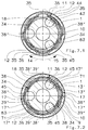
- the drill chucks shown in the drawing serve to receive a drill, not shown, and each have a chuck body 1 for connection to a drilling spindle, also not shown.
- the chuck body 1 has a threaded receptacle 2, to which an axial passage (also not shown) can connect to the front, through which the blows of a racket or striker which is displaceably guided in the hollow rotating spindle directly onto the shaft end of the tool holder 4 of the drill chuck held can be transferred.
- the drill chucks have axially guiding and / or clamping jaws 5 centering the drill, which are adjustable in the tool holder 4 coaxial to the chuck axis 3 and centered in relation to the chuck axis and are guided in guide channels 43 which run inclined in the chuck body 1 to the chuck axis 3 and which have their rear mouth 44 cut the peripheral surface of the chuck body 1.
- Mouths 44 engage the clamping jaws with a toothing 6 in a clamping thread 7 of a clamping ring 8, which is guided axially immovably and rotatably on the chuck body 1 and is rotated by hand relative to the chuck body 1 by means of a likewise axially immovable clamping sleeve 9 for clamping and releasing the chuck can.
- the clamping ring 8 is supported axially to the rear via a ball bearing 22 and a bearing ring 21 on the chuck body 1. In order to prevent undesired adjustments of the clamping jaws 5, the rotational position of the clamping ring 8 can be fixed.
- a locking device for this purpose, consists of a coaxial ring of locking recesses 10 on the side of the chuck body 1 and at least one locking member 12 which engages in the locking recesses 10 under spring force.
- the locking member 12 and the locking recesses 10 receiving it abut each other in such inclined flank surfaces 13 ', 13''that they lock the clamping ring 8 against rotation in the direction of rotation corresponding to the opening of the drill chuck (arrow 14) when the clamping ring 8 is rotated by hand with a sufficiently large torque in the opposite direction, i.e.
- the locking member 12 can be adjusted between its engaged and disengaged states on the locking recesses 10, for which purpose it can be adjusted by a control cam 35 on the clamping sleeve 9 and the clamping sleeve 9 can accordingly be rotated relative to the clamping ring 8.
- This rotation of the clamping sleeve 9 relative to the clamping ring 8 is positively limited in both directions of rotation (arrows 14, 15), for which purpose stops 16 ', 16''are provided.
- the locking member 12 moves from the disengaged state to the engaged state and vice versa, that is to say by rotating the clamping sleeve 9 in the direction of rotation corresponding to the opening of the drill chuck (arrow 14 ) from the engaged state to the disengaged state.
- a locking device generally designated 17, which has two locking positions in the circumferential direction, the locking member 12 being in the engaged state in the locking recesses 10 in the one locking position and in the disengaged state in the other locking position , as a comparison of the pairs of figures 3.1, 3.2 or 7.1, 7.2 or 9.1, 9.2 or 12.1, 12.2 reveals.
- the rim of the locking recesses 10 is in all cases in the area of the mouths 44 of the guide channels 43, specifically in the exemplary embodiments according to FIGS. 1 to 5, on a casing which surrounds the chuck body 1 in the mouth area of the guide channels 43 and which is non-rotatable Mouth 44 bridging body ring 21, 46.
- this body ring is formed by the bearing ring 21 held non-rotatably on the chuck body 1 and correspondingly arranged axially behind the clamping thread 7 of the clamping ring 8.
- the body ring 46 is provided in addition to the bearing ring 21 and is arranged axially in front of the clamping thread 7.
- the ring of the locking recesses 10 on the body ring 21, 46 also has no interruptions in the mouth region of the guide channels 43, a single locking member 12 is sufficient for the locking device 11 to enable locking engagement of the locking member 12 in one of the locking recesses 10 in each rotational position of the clamping ring 8 .
- the rim of the locking recesses 10 is formed directly on the chuck body 1, so that the mouths 44 of the guide channels 43 in the rim of the locking recesses 10 generate interruptions 45.
- the arrangement of the ring of the locking recesses 10 realized in the exemplary embodiments is recommended directly on the chuck body 1 axially behind the clamping thread 7, that is to say in a region of the chuck body in which the outer diameter of the chuck body 1 and thus the ring of the blocking recesses 10 are large and therefore correspondingly large is the locking torque that can be transmitted by the locking device 11.
- the clamping ring 8 has a coaxial intermediate ring 18 which forms a guide for the clamping sleeve 9 and which carries the parts of the stops 16 ', 16' 'for the clamping sleeve 9, the locking device 11 (locking member 12) and the locking device 17 on the clamping ring side, and a collar part 18' comprises the part 8 'of the clamping ring 8 which carries the clamping thread 7 in a rotationally fixed manner.
- the part 8 'of the clamping ring 8 which carries the clamping thread 7 consists of two circumferentially divided ring halves which are initially weakened at each division by a bore 19 and then broken, which are put together in an annular groove 20 of the chuck body 1 and by the collar part 18' on Chuck body 1 are held together.
- the clamping ring 8 can also be formed in one piece, but this is not shown in the drawing.
- stop pieces generally designated 29 are provided on one part, ie clamping ring 8 or clamping sleeve 9, and a recess 30 receiving the stop piece 29 on the other part, the stop piece 29 at the ends of the Rotation path comes to a stop with one of the two end faces 16 ', 16''which delimit the cutout 30 in the circumferential direction.
- the stop pieces 29 are designed as wall pieces of the intermediate ring 18, which project axially forward from the front edge of the intermediate ring 18 into the recesses 30 formed on the inside of the clamping sleeve 9.
- the latching device 17 is formed by latching elements which come into engagement with one another in the two latching positions, namely a latching member 38 ′′ and latching receptacles 17 ′′.
- the clamping ring 8, or its intermediate ring 18, has spring webs 34 which extend in the circumferential direction and on which the locking projection 38 ′′ is located, while the locking receptacles 17 ′′ are formed on the inside of the clamping sleeve 9.
- the spring bars 34 are equipped with the spring travel required for the latching process.
- a separate control cam 35 is formed on the clamping sleeve 9 in order to control each locking member 12.
- Each locking member 12 is located on its own spring arm 36, which extends in the circumferential direction and is carried by the tension ring 8 or by its intermediate ring 18.
- the spring arm 36 of the control cam 35 rests at such a distance from the locking member 12. that the spring arm 36 can bounce at the location of the locking member 12 by its depth of engagement in the locking recesses 10, so that when Rotation of the clamping sleeve 9 relative to the chuck body 1 in the direction of rotation corresponding to the chucking of the chuck (arrow 15) can cause the locking member 12 to slide over the locking recesses 10 in the manner already described.
- the spring bars 34 and spring arms 36 can, as in FIGS. 8 and 9, be formed by spring band pieces 47, 48 which are independent of one another, the latching member 38 ′′ being bent as a projection on the spring band piece 47.
- the spring band pieces 48 have correspondingly formed projections 38 ', which form the abutment of the spring arm 36 on the control cam 35.
- a spring clip 38 which extends in the circumferential direction and is connected in a rotationally locking manner to the clamping ring 8 or its intermediate ring 18, forms both the spring arm 36 and the spring bars 34.
- the two projections 38 ', 38' 'on the spring clip 38 arranged in the circumferential direction at a mutual distance.
- the locking member-side projection 38 ' forms the abutment of the spring arm 36 on the control cam 35, the other projection 38' 'the locking member of the locking device 17.
- the spring clip 38 is formed by a spring band and the locking member 12 directly by the rear end of the spring band, seen in the direction of rotation of the clamping ring 8 corresponding to the closing of the chuck (arrow 15).
- the projections 38 ', 38' ' are each bent in the form of bulges on the spring band.
- the spring clips 38 are in a slot 94 running between the chuck body 1 and the clamping sleeve 9 in the circumferential direction arranged and secured on the clamping ring 8 against rotation in a manner to be described in more detail.
- the spring clips 38 lie in the slot 94 with radial alignment of the spring band surface to the chuck axis 3 and the locking recesses 10 accordingly run radially on an annular surface 74 on the chuck body side, perpendicular to the chuck axis 3, but interrupted by the orifices 44.
- annular shoulder 75 of the clamping sleeve 9 is a radial annular shoulder 75 of the clamping sleeve 9, the annular shoulder 75 being formed on a sleeve part 9 ′ which is part of the clamping sleeve 9 and is axially immovable and non-rotatably connected to the clamping sleeve 9.
- the control cams 35 and the locking receptacles 17 ′′ are formed on the rin shoulder 75.
- the intermediate ring 38 passes through short tongues 49 in the spring clip 38 in openings, the edges 78 of which bear against the tongues 49 in the circumferential direction, so that the spring clip 38 cannot rotate relative to the intermediate ring 18 and thus the clamping ring 8.
- the spring clips 38 which are aligned with their spring band surface parallel to the chuck axis 3, lie in a circumferential direction between the chuck body 1 and the intermediate ring 18, which is limited on the chuck body side by the ring of the axially extending locking recesses 10.
- the spring clip 38 lies with the outward bias against the intermediate ring 18 and, with its two projections 38 ', 38'', extends radially outward through the intermediate ring 18 in windows 39', 39 ''.
- the projections 38 ', 38'' which pass through these windows 39', 39 '' secure the spring clip 38 by abutment against the window edges delimiting the windows in the circumferential direction against rotation relative to the intermediate ring 18.
- the radial width of the ring slot 83 is greater than the corresponding thickness of the spring clip 38, which is supported with an apex region 31 located approximately centrally between the two projections 38 ', 38''on the intermediate ring 18 and Between this apex region 31 and the two projections 38 ', 38''each form one of the spring bars 34 for tangential contact with the rim of the locking recesses 10.
- the pretension of the spring clip 38 keeps the locking member 12 out of engagement with the locking recesses 10; in the locked state, it must be pressed into the locking recesses 10 via the control cam 35.
- both spring webs 34 resiliently rest on the ring of locking recesses 10, so that the spring clip 38 adjusts itself automatically in its position in the ring slot 83.
- a spring leg 71 which the spring bracket 38 forms with its end facing away from the projection 38 ′′ and which also bears against the ring of the locking recesses 10 under tension, has also proven to be advantageous.
- the two spring bars 34 and the spring leg 71 which are in contact with the chuck body 1, furthermore exert a braking effect by means of which vibrations on the chuck body 1, clamping ring 8 or intermediate ring 18 and adjusting ring 9 occurring during drilling operation are damped.
- the two projections 38 ′, 38 ′′ can, as in FIGS. 1 to 5, lie approximately diametrically opposite in relation to the chuck axis 3.
- the spring clip 38 has a third in the apex region between its two projections 38 ′, 38 ′′, the intermediate ring 18 in a further one Window 39 '''outward projection 38'''.
- This projection 38 ′′ engages in a groove 70 provided on the inside of the clamping sleeve 9, which extends in the circumferential direction at least over the maximum possible rotation path of the clamping sleeve 9 relative to the clamping ring 8.
- This groove 70 forms with its two side walls an axial contact for the projection 38 ''', whereby the clamping sleeve 9 can be secured against axial displacements on the clamping ring 8.
- a comparable axial guiding function is not recommended for the two projections 38 ', 38'', however, since here the contact of the spring clip 38 on the side walls of corresponding grooves impair the mobility of the two projections 38', 38 '' required for the locking or latching process could.
- FIGS. 1 to 3.1, 3.2: 1 to 4.1 show the drill chuck in the unlocked state.
- the spring arm 36 is adjusted radially outwards, so that the locking member 12 is outside the locking recesses 10.
- the locking projection 38 '' which engages in the locking recess 17 '' secures the intermediate ring 18 and the clamping sleeve 9 against rotation against one another, so that when the clamping sleeve 9 is rotated via the intermediate ring 18 the clamping ring 8 can be freely rotated relative to the chuck body 1 as long as the drill chuck is open.
- the clamping ring 8 is first carried along in the manner already described until the clamping jaws 5 come to rest on the tool shank. A further entrainment of the clamping ring 8 by the clamping sleeve 9 is then no longer possible, so that the clamping sleeve 9 moves overcoming the locking device 17 into the position shown in FIG. 4.2 relative to the intermediate ring 18. In this position, the clamping sleeve 9 presses the spring arm 36 radially inward via the control cam 35 and thus the locking member 12 into the engaged state on the locking recesses 10.
- the clamping ring 8 is against the chuck body 1 against rotation in the direction of arrow 14 and thus secured against unwanted opening of the drill chuck.
- the drill chuck can be clamped further and more tightly, namely the clamping sleeve 9 can be rotated relative to the chuck body 1 in the direction of arrow 15, with the clamping sleeve 9 now tightening the intermediate ring 18 and thus the clamping ring 8 in the direction of arrow 15 via the stops 16 ′′ .
- the clamping sleeve 9 is first rotated in the direction of the arrow 14, the latching device 17 being adjusted again first and the stop pieces 29 in the cutouts 30 again being visible in FIG.
- the clamping sleeve 9 can therefore extend axially over practically the entire length of the drill chuck to the axially rear chuck end and thereby form the only chuck handle accessible from the outside of the hand. Only if it is nevertheless desired to be able to manipulate the chuck body 1 independently of the drilling spindle is it advisable to provide a retaining ring for the chuck body 1, which must then be connected to the chuck body in a rotationally fixed manner. Such a retaining ring 54 can also be formed in one piece with the chuck body 1.
Landscapes
- Engineering & Computer Science (AREA)
- Mechanical Engineering (AREA)
- Gripping On Spindles (AREA)
- Percussive Tools And Related Accessories (AREA)
- Clamps And Clips (AREA)
- Drilling And Boring (AREA)
- Spinning Or Twisting Of Yarns (AREA)
- Apparatus For Making Beverages (AREA)
Priority Applications (1)
| Application Number | Priority Date | Filing Date | Title |
|---|---|---|---|
| DE29522204U DE29522204U1 (de) | 1994-10-31 | 1995-04-10 | Bohrfutter |
Applications Claiming Priority (2)
| Application Number | Priority Date | Filing Date | Title |
|---|---|---|---|
| DE4438991 | 1994-10-31 | ||
| DE4438991A DE4438991C5 (de) | 1994-10-31 | 1994-10-31 | Bohrfutter |
Publications (3)
| Publication Number | Publication Date |
|---|---|
| EP0710520A2 true EP0710520A2 (fr) | 1996-05-08 |
| EP0710520A3 EP0710520A3 (fr) | 1998-05-20 |
| EP0710520B1 EP0710520B1 (fr) | 2001-07-18 |
Family
ID=6532213
Family Applications (9)
| Application Number | Title | Priority Date | Filing Date |
|---|---|---|---|
| EP95105380A Expired - Lifetime EP0710519B1 (fr) | 1994-10-31 | 1995-04-10 | Mandrin porte-foret |
| EP00113207A Expired - Lifetime EP1043100B1 (fr) | 1994-10-31 | 1995-04-10 | Mandrin de serrage |
| EP06014430A Withdrawn EP1724041A1 (fr) | 1994-10-31 | 1995-04-10 | Mandrin de perceuse, en particulier pour perçage à percussion |
| EP95105379A Expired - Lifetime EP0710518B1 (fr) | 1994-10-31 | 1995-04-10 | Mandrin porte-foret |
| EP07005517A Expired - Lifetime EP1792678B1 (fr) | 1994-10-31 | 1995-04-10 | Mandrin de perceuse, en particulier pour perçage à percussion |
| EP00116860A Expired - Lifetime EP1055472B1 (fr) | 1994-10-31 | 1995-04-10 | Mandrin de forage |
| EP04010757A Expired - Lifetime EP1452255B1 (fr) | 1994-10-31 | 1995-04-10 | Mandrin de perceuse, en particulier pour perçage à percussion |
| EP02001527A Expired - Lifetime EP1224993B1 (fr) | 1994-10-31 | 1995-04-10 | Mandrin de forage |
| EP95105407A Expired - Lifetime EP0710520B1 (fr) | 1994-10-31 | 1995-04-10 | Mandrin porte-foret |
Family Applications Before (8)
| Application Number | Title | Priority Date | Filing Date |
|---|---|---|---|
| EP95105380A Expired - Lifetime EP0710519B1 (fr) | 1994-10-31 | 1995-04-10 | Mandrin porte-foret |
| EP00113207A Expired - Lifetime EP1043100B1 (fr) | 1994-10-31 | 1995-04-10 | Mandrin de serrage |
| EP06014430A Withdrawn EP1724041A1 (fr) | 1994-10-31 | 1995-04-10 | Mandrin de perceuse, en particulier pour perçage à percussion |
| EP95105379A Expired - Lifetime EP0710518B1 (fr) | 1994-10-31 | 1995-04-10 | Mandrin porte-foret |
| EP07005517A Expired - Lifetime EP1792678B1 (fr) | 1994-10-31 | 1995-04-10 | Mandrin de perceuse, en particulier pour perçage à percussion |
| EP00116860A Expired - Lifetime EP1055472B1 (fr) | 1994-10-31 | 1995-04-10 | Mandrin de forage |
| EP04010757A Expired - Lifetime EP1452255B1 (fr) | 1994-10-31 | 1995-04-10 | Mandrin de perceuse, en particulier pour perçage à percussion |
| EP02001527A Expired - Lifetime EP1224993B1 (fr) | 1994-10-31 | 1995-04-10 | Mandrin de forage |
Country Status (5)
| Country | Link |
|---|---|
| US (1) | US5765839A (fr) |
| EP (9) | EP0710519B1 (fr) |
| JP (1) | JP3774793B2 (fr) |
| DE (13) | DE4438991C5 (fr) |
| ES (7) | ES2176146T3 (fr) |
Cited By (14)
| Publication number | Priority date | Publication date | Assignee | Title |
|---|---|---|---|---|
| WO1998014294A1 (fr) * | 1996-10-02 | 1998-04-09 | Power Tool Holders Incorporated | Mandrin |
| US5816582A (en) * | 1995-08-11 | 1998-10-06 | Power Tool Holders Incor. | Chuck |
| US5816583A (en) * | 1996-12-04 | 1998-10-06 | Power Tool Holders, Inc. | Integral locking sleeve chuck |
| US5957469A (en) * | 1996-09-25 | 1999-09-28 | Power Tool Holders, Inc. | Spring chuck |
| US6260856B1 (en) | 1999-11-17 | 2001-07-17 | Power Tool Holders Incorporated | Locking chuck |
| US6390481B1 (en) | 2000-03-10 | 2002-05-21 | Power Tool Holders Incorporated | Locking chuck |
| US6540237B1 (en) | 2000-06-23 | 2003-04-01 | Power Tool Holders Incorporated | Chuck |
| US7451990B2 (en) | 2004-04-29 | 2008-11-18 | Jacobs Chuck Manufacturing Company | Chuck with torque indicator |
| US7708288B2 (en) | 2005-05-18 | 2010-05-04 | Jacobs Chuck Manufacturing Company | Locking chuck |
| US7748719B2 (en) | 2005-06-09 | 2010-07-06 | Jacobs Chuck Manufacturing Company | Drill chuck |
| US7837200B2 (en) | 2005-07-01 | 2010-11-23 | Jacobs Chuck Manufacturing Company | Chuck |
| US7900937B2 (en) | 2007-08-17 | 2011-03-08 | Jacobs Chuck Manufacturing Company | Locking chuck |
| US8376371B2 (en) | 2008-09-17 | 2013-02-19 | Jacobs Chuck Manufacturing Company | Locking chuck jaws |
| US8616561B2 (en) | 2012-04-10 | 2013-12-31 | Apex Brands, Inc. | Locking chuck |
Families Citing this family (86)
| Publication number | Priority date | Publication date | Assignee | Title |
|---|---|---|---|---|
| DE59606508D1 (de) * | 1996-01-17 | 2001-04-05 | Roehm Gmbh | Bohrfutter |
| US5913524A (en) * | 1997-10-08 | 1999-06-22 | Power Tool Holders, Inc. | Chuck with gripping mechanism stop |
| USD404630S (en) * | 1998-05-20 | 1999-01-26 | Black & Decker Inc. | Chuck |
| DE19832891C2 (de) * | 1998-07-22 | 2003-04-17 | Roehm Gmbh | Bohrfutter |
| DE19907331A1 (de) | 1999-02-20 | 2000-08-24 | Roehm Gmbh | Bohrfutter |
| USD423527S (en) * | 1999-07-13 | 2000-04-25 | Yukiwa Seiko Kabushiki Kaisha | Drill chuck |
| USD433909S (en) * | 1999-12-23 | 2000-11-21 | Ryobi North America, Inc. | Keyless drill chuck |
| USD434629S (en) * | 1999-12-23 | 2000-12-05 | Ryobi North America, Inc. | Keyless drill chuck |
| DE10008262B4 (de) | 2000-02-23 | 2007-03-15 | Röhm Gmbh | Verfahren zur Herstellung von Hartmetalleinsätze als Spannschneiden aufweisende Spannbacken für Bohrfutter, sowie entsprechend gefertigte Spannbacken |
| EP1170078B1 (fr) * | 2000-07-03 | 2003-09-10 | Röhm GmbH | Bague de serrage ayant une came de commande |
| EP1170079B2 (fr) * | 2000-07-03 | 2010-10-06 | Röhm GmbH | Mandrin à forer |
| US6517088B1 (en) * | 2000-08-08 | 2003-02-11 | Rohm Gmbh | Lockable drill chuck |
| DE10137281A1 (de) | 2000-08-10 | 2002-02-21 | Roehm Gmbh | Bohrfutter |
| JP4681716B2 (ja) * | 2000-08-14 | 2011-05-11 | ロェーム ゲーエムベーハー | 切り替え・調節用曲がり部を有する締付ケーシング筒を備えたドリルチャック |
| DE10101212A1 (de) | 2001-01-11 | 2002-07-18 | Roehm Gmbh | Bohrfutter |
| CN1217762C (zh) | 2001-06-10 | 2005-09-07 | 山东威达机械股份有限公司 | 自锁钻夹头 |
| US6959931B2 (en) | 2001-08-30 | 2005-11-01 | Yukiwa Seiko Inc. | Keyless chuck and associated method |
| JP2003071618A (ja) | 2001-08-30 | 2003-03-12 | Yukiwa Seiko Inc | チャック装置 |
| US6824141B1 (en) | 2001-08-30 | 2004-11-30 | Yukiwa Seiko Kabushiki Kaisha | Chuck device |
| US6860488B2 (en) * | 2001-10-10 | 2005-03-01 | Rohm Gmbh | Drill chuck with front-end shield |
| USD461697S1 (en) | 2001-11-05 | 2002-08-20 | Techtronic Co., Ltd | Keyless drill chuck |
| USD472443S1 (en) | 2001-11-05 | 2003-04-01 | Techtronic Industries Co., Ltd | Keyless drill chuck |
| JP4015857B2 (ja) | 2002-01-18 | 2007-11-28 | ユキワ精工株式会社 | チャック装置 |
| JP4053301B2 (ja) | 2002-01-31 | 2008-02-27 | ユキワ精工株式会社 | チャック装置 |
| DE10207152B4 (de) * | 2002-02-20 | 2015-04-16 | Röhm Gmbh | Bohrvorrichtung |
| DE10226165A1 (de) * | 2002-06-12 | 2003-12-24 | Roehm Gmbh | Bohrfutter |
| DE10226429A1 (de) * | 2002-06-13 | 2003-12-24 | Roehm Gmbh | Bohrfutter |
| DE10237750A1 (de) * | 2002-08-17 | 2004-02-26 | Röhm Gmbh | Bohrfutter |
| FR2847180B1 (fr) * | 2002-11-18 | 2005-02-11 | Amyot Ets Sa | Mandrin porte-outil a systeme de verrouillage |
| JP4294945B2 (ja) * | 2002-12-06 | 2009-07-15 | ユキワ精工株式会社 | チャック装置 |
| CN2633481Y (zh) * | 2003-07-17 | 2004-08-18 | 山东威达机械股份有限公司 | 锁紧式钻夹头 |
| DE10335500A1 (de) * | 2003-07-31 | 2005-03-03 | Röhm Gmbh | Schnellspannbohrfutter |
| US20050087937A1 (en) * | 2003-10-22 | 2005-04-28 | Wenhua Zhou | Lock type manually tightened chuck |
| DE20317695U1 (de) * | 2003-11-14 | 2004-02-19 | Röhm Gmbh | Bohrvorrichtung |
| CN2715890Y (zh) * | 2004-08-03 | 2005-08-10 | 山东威达机械股份有限公司 | 带响自锁式钻夹头 |
| DE102004044824A1 (de) * | 2004-09-16 | 2006-03-23 | Röhm Gmbh | Bohrfutter |
| US7331584B2 (en) | 2004-09-17 | 2008-02-19 | Black & Decker Inc. | Chuck with nutating gear reduction |
| EP1861220A1 (fr) * | 2005-03-19 | 2007-12-05 | Röhm GmbH | Mandrin de perceuse |
| DE102005018392B4 (de) * | 2005-04-20 | 2019-10-31 | Röhm Gmbh | Bohrfutter |
| FR2886183B1 (fr) * | 2005-05-27 | 2007-07-13 | Amyot Sa Sa Ets | Mandrin porte-outil pour l'equipement d'une machine tournante, notamment du type "cle a choc" |
| US7527273B2 (en) | 2005-09-02 | 2009-05-05 | Jacobs Chuck Manufacturing Company | Locking chuck |
| CN100578036C (zh) * | 2005-09-28 | 2010-01-06 | 山东威达机械股份有限公司 | 单向离合装置及采用该装置的柄类工具夹持结构 |
| DE102005048167B4 (de) * | 2005-10-06 | 2007-06-06 | Röhm Gmbh | Bohrfutter |
| US7637510B2 (en) * | 2005-10-12 | 2009-12-29 | Shandong Weida Machinery Company Limited | Chuck with gripping mechanism stop |
| USD537315S1 (en) * | 2005-10-20 | 2007-02-27 | Jacobs Chuck Manufacturing Company | Drill chuck sleeve |
| DE102005058657A1 (de) * | 2005-12-07 | 2007-06-14 | Röhm Gmbh | Bohrfutter |
| FR2897789B1 (fr) * | 2006-02-27 | 2008-05-09 | Amyot Sa Sa Ets | Mandrin porte-outil pour l'equipement d'une machine tourante muni de moyens de verrouillage radial et axial sequences |
| DE102006011344A1 (de) * | 2006-03-11 | 2007-09-13 | Röhm Gmbh | Bohrfutter |
| DE102007008314A1 (de) * | 2006-03-25 | 2007-09-27 | Röhm Gmbh | Nachspannendes Bohrfutter |
| CN101077536B (zh) * | 2006-05-23 | 2010-12-01 | 山东威达机械股份有限公司 | 斜楔面锁紧钻夹头 |
| DE102006024819B4 (de) * | 2006-05-29 | 2024-05-23 | Röhm Gmbh | Bohrfutter |
| US7845651B2 (en) | 2006-08-15 | 2010-12-07 | Jacobs Chuck Manufacturing Company | Locking chuck |
| DE102006043040A1 (de) * | 2006-09-14 | 2008-03-27 | Röhm Gmbh | Bohrfutter |
| DE102006050916A1 (de) * | 2006-10-28 | 2008-04-30 | Röhm Gmbh | Nachspannendes Bohrfutter |
| ES2327358T3 (es) * | 2006-12-23 | 2009-10-28 | Rohm Gmbh | Portabrocas. |
| US8057134B2 (en) | 2007-06-26 | 2011-11-15 | Techtronic Power Tools Technology Limited | Chuck assembly |
| US8075229B2 (en) * | 2007-06-26 | 2011-12-13 | Techtronic Power Tools Technology Limited | Multi-speed drill and chuck assembly |
| CN101497190B (zh) * | 2008-01-31 | 2012-03-28 | 苏州宝时得电动工具有限公司 | 电动工具 |
| US8403339B2 (en) | 2008-06-18 | 2013-03-26 | Jacobs Chuck Manufacturing Company | Self tightening chuck with an axial lock |
| DE202009005187U1 (de) * | 2008-11-24 | 2009-10-29 | Zhejiang Sanou Machinery Co. Ltd., Taizhou | Schlüsselloses Bohrfutter mit Selbstverriegelung |
| US8777232B2 (en) | 2009-07-29 | 2014-07-15 | Jacobs Chuck Manufacturing Company | Self-tightening chuck with a radial lock |
| DE202012102742U1 (de) * | 2012-07-23 | 2013-04-25 | Röhm Gmbh | Bohrfutter |
| CN202779945U (zh) | 2012-08-01 | 2013-03-13 | 山东威达机械股份有限公司 | 钻夹头 |
| DE102012110809A1 (de) | 2012-11-12 | 2014-05-15 | Röhm Gmbh | Bohrfutter |
| US10556276B2 (en) * | 2013-03-14 | 2020-02-11 | Apex Brands, Inc. | Locking chuck |
| DE202013101255U1 (de) | 2013-03-25 | 2013-04-10 | Röhm Gmbh | Bohrfutter |
| DE102014002969A1 (de) * | 2014-03-06 | 2015-09-10 | Röhm Gmbh | Bohrfutter |
| DE102014106082B4 (de) | 2014-04-30 | 2025-07-03 | Röhm Gmbh | Bohrfutter |
| DE102014108723A1 (de) | 2014-06-23 | 2015-12-24 | Röhm Gmbh | Bohrfutter |
| US9701032B2 (en) | 2014-07-23 | 2017-07-11 | Black & Decker Inc. | Power tool accessory with brace |
| USD730141S1 (en) | 2014-08-15 | 2015-05-26 | Black & Decker Inc. | Shear accessory |
| DE102015102241B4 (de) | 2015-02-17 | 2024-10-02 | Röhm Gmbh | Bohrfutter |
| US10239127B2 (en) | 2015-08-12 | 2019-03-26 | Jacobs Chuck Manufacturing (Suzhou) Company, Ltd. | Locking chuck |
| CN105345100B (zh) * | 2015-12-18 | 2019-09-24 | 山东威达机械股份有限公司 | 一种可释放变形力的带锁手紧钻夹头 |
| CN205702524U (zh) * | 2016-04-25 | 2016-11-23 | 浙江三鸥机械股份有限公司 | 一种自锁式钻夹头 |
| JP6787571B2 (ja) * | 2016-12-06 | 2020-11-18 | ユキワ精工株式会社 | チャック装置 |
| DE102016224186A1 (de) * | 2016-12-06 | 2018-06-07 | Robert Bosch Gmbh | Adaptervorsatz zum Einspannen eines Rundschafteinsatzwerkzeugs |
| CN109351995B (zh) | 2018-11-05 | 2024-07-30 | 台州三锦工业机器有限公司 | 手紧带锁钻夹头 |
| CN110052633A (zh) * | 2019-04-25 | 2019-07-26 | 山东威达雷姆机械有限公司 | 一种轴向锁紧钻夹头 |
| DE102020000411A1 (de) | 2020-01-24 | 2021-07-29 | Hakki Aygün | Gewindeschneidfutter |
| US12011820B2 (en) | 2020-02-04 | 2024-06-18 | Black & Decker Inc. | Power tool and tool bit holding system |
| DE102020131833A1 (de) * | 2020-12-01 | 2022-06-02 | Röhm Gmbh | Bohrfutter |
| WO2023019434A1 (fr) * | 2021-08-17 | 2023-02-23 | Jacobs Chuck Manufactuirng (Suzhou) Company, Ltd. | Mandrin à manchon de verrouillage |
| USD1034129S1 (en) * | 2022-03-23 | 2024-07-09 | Biocut, Llc | Chuck |
| DE102023134201A1 (de) * | 2023-12-06 | 2025-06-12 | Röhm Gmbh | Bohrfutter sowie Bohrmaschine |
| DE102023135846A1 (de) * | 2023-12-19 | 2025-06-26 | Röhm Gmbh | Bohrfutter sowie Bohrmaschine |
Family Cites Families (7)
| Publication number | Priority date | Publication date | Assignee | Title |
|---|---|---|---|---|
| DE2341642C3 (de) * | 1973-08-17 | 1981-10-01 | Metabowerke KG Closs, Rauch & Schnizler, 7440 Nürtingen | Spannfutter für Bohrer |
| DE7910976U1 (de) * | 1979-04-14 | 1979-07-19 | Roehm, Guenter Horst, 7927 Sontheim | Nachspannendes bohrfutter |
| JPH0783961B2 (ja) * | 1991-06-13 | 1995-09-13 | ユキワ精工株式会社 | 工具用チャック |
| US5232230A (en) * | 1992-09-28 | 1993-08-03 | Lin Pi Chu | Chuck assembly for a drilling apparatus |
| DE4238503C1 (de) * | 1992-11-14 | 1993-11-25 | Roehm Guenter H | Bohrfutter |
| FR2702975B1 (fr) * | 1993-03-26 | 1995-06-16 | Amyot Ets Sa | Mandrin porte-outil pour l'equipement d'une machine tournante, telle qu'une perceuse. |
| DE4313742C2 (de) * | 1993-04-27 | 2000-10-05 | Roehm Guenter H | Bohrfutter |
-
1994
- 1994-10-31 DE DE4438991A patent/DE4438991C5/de not_active Expired - Lifetime
-
1995
- 1995-04-10 EP EP95105380A patent/EP0710519B1/fr not_active Expired - Lifetime
- 1995-04-10 DE DE29522206U patent/DE29522206U1/de not_active Expired - Lifetime
- 1995-04-10 DE DE59509423T patent/DE59509423D1/de not_active Expired - Lifetime
- 1995-04-10 DE DE59508972T patent/DE59508972D1/de not_active Expired - Lifetime
- 1995-04-10 ES ES00113207T patent/ES2176146T3/es not_active Expired - Lifetime
- 1995-04-10 ES ES00116860T patent/ES2161673T3/es not_active Expired - Lifetime
- 1995-04-10 ES ES02001527T patent/ES2220838T3/es not_active Expired - Lifetime
- 1995-04-10 ES ES95105407T patent/ES2159582T3/es not_active Expired - Lifetime
- 1995-04-10 DE DE59510304T patent/DE59510304D1/de not_active Expired - Lifetime
- 1995-04-10 DE DE59509594T patent/DE59509594D1/de not_active Expired - Lifetime
- 1995-04-10 ES ES07005517T patent/ES2359887T3/es not_active Expired - Lifetime
- 1995-04-10 DE DE29522446U patent/DE29522446U1/de not_active Expired - Lifetime
- 1995-04-10 DE DE59508971T patent/DE59508971D1/de not_active Expired - Lifetime
- 1995-04-10 ES ES95105380T patent/ES2153441T3/es not_active Expired - Lifetime
- 1995-04-10 DE DE29522207U patent/DE29522207U1/de not_active Expired - Lifetime
- 1995-04-10 EP EP00113207A patent/EP1043100B1/fr not_active Expired - Lifetime
- 1995-04-10 DE DE59511065T patent/DE59511065D1/de not_active Expired - Lifetime
- 1995-04-10 DE DE59511111T patent/DE59511111D1/de not_active Expired - Lifetime
- 1995-04-10 EP EP06014430A patent/EP1724041A1/fr not_active Withdrawn
- 1995-04-10 DE DE29522204U patent/DE29522204U1/de not_active Expired - Lifetime
- 1995-04-10 DE DE59510926T patent/DE59510926D1/de not_active Expired - Lifetime
- 1995-04-10 EP EP95105379A patent/EP0710518B1/fr not_active Expired - Lifetime
- 1995-04-10 EP EP07005517A patent/EP1792678B1/fr not_active Expired - Lifetime
- 1995-04-10 EP EP00116860A patent/EP1055472B1/fr not_active Expired - Lifetime
- 1995-04-10 ES ES95105379T patent/ES2153440T3/es not_active Expired - Lifetime
- 1995-04-10 EP EP04010757A patent/EP1452255B1/fr not_active Expired - Lifetime
- 1995-04-10 EP EP02001527A patent/EP1224993B1/fr not_active Expired - Lifetime
- 1995-04-10 EP EP95105407A patent/EP0710520B1/fr not_active Expired - Lifetime
- 1995-10-23 US US08/553,797 patent/US5765839A/en not_active Expired - Lifetime
- 1995-10-26 JP JP27868995A patent/JP3774793B2/ja not_active Expired - Fee Related
Cited By (34)
| Publication number | Priority date | Publication date | Assignee | Title |
|---|---|---|---|---|
| US5816582A (en) * | 1995-08-11 | 1998-10-06 | Power Tool Holders Incor. | Chuck |
| US5957469A (en) * | 1996-09-25 | 1999-09-28 | Power Tool Holders, Inc. | Spring chuck |
| CN1087201C (zh) * | 1996-10-02 | 2002-07-10 | 动力工具霍德尔斯公司 | 卡头 |
| US5741016A (en) * | 1996-10-02 | 1998-04-21 | Power Tool Holders Incorporated | Chuck |
| WO1998014294A1 (fr) * | 1996-10-02 | 1998-04-09 | Power Tool Holders Incorporated | Mandrin |
| US5816583A (en) * | 1996-12-04 | 1998-10-06 | Power Tool Holders, Inc. | Integral locking sleeve chuck |
| US6260856B1 (en) | 1999-11-17 | 2001-07-17 | Power Tool Holders Incorporated | Locking chuck |
| US6390481B1 (en) | 2000-03-10 | 2002-05-21 | Power Tool Holders Incorporated | Locking chuck |
| DE10111750B4 (de) * | 2000-03-10 | 2004-11-18 | Power Tool Holders Inc., Christiana | Verriegelungsfutter |
| DE10111750C5 (de) * | 2000-03-10 | 2011-12-01 | Power Tool Holders Inc. | Verriegelungsfutter |
| US6540237B1 (en) | 2000-06-23 | 2003-04-01 | Power Tool Holders Incorporated | Chuck |
| US7451990B2 (en) | 2004-04-29 | 2008-11-18 | Jacobs Chuck Manufacturing Company | Chuck with torque indicator |
| US7722054B2 (en) | 2004-04-29 | 2010-05-25 | Jacobs Chuck Manufacturing Company | Chuck with torque indicator |
| US7984913B2 (en) | 2005-05-18 | 2011-07-26 | Jacobs Chuck Manufacturing Company | Locking chuck |
| US7708288B2 (en) | 2005-05-18 | 2010-05-04 | Jacobs Chuck Manufacturing Company | Locking chuck |
| US9364900B2 (en) | 2005-05-18 | 2016-06-14 | Apex Brands, Inc. | Locking chuck |
| US8678400B2 (en) | 2005-05-18 | 2014-03-25 | Apex Brands, Inc. | Locking chuck |
| US8328205B2 (en) | 2005-05-18 | 2012-12-11 | Jacobs Chuck Manufacturing Company | Locking chuck |
| US8511692B2 (en) | 2005-06-09 | 2013-08-20 | Jacobs Chuck Manufacturing Company | Drill chuck |
| US9221105B2 (en) | 2005-06-09 | 2015-12-29 | Apex Brands, Inc. | Drill chuck |
| US8191902B2 (en) | 2005-06-09 | 2012-06-05 | Jacobs Chuck Manufacturing Company | Drill chuck |
| US7997587B2 (en) | 2005-06-09 | 2011-08-16 | Jacobs Chuck Manufacturing Company | Drill chuck |
| US7748719B2 (en) | 2005-06-09 | 2010-07-06 | Jacobs Chuck Manufacturing Company | Drill chuck |
| US8695991B2 (en) | 2005-06-09 | 2014-04-15 | Apex Brands, Inc. | Drill chuck |
| US8029000B2 (en) | 2005-07-01 | 2011-10-04 | Jacobs Chuck Manufacturing Company | Chuck |
| US8387995B2 (en) | 2005-07-01 | 2013-03-05 | Jacobs Chuck Manufacturing Company | Chuck |
| US7837200B2 (en) | 2005-07-01 | 2010-11-23 | Jacobs Chuck Manufacturing Company | Chuck |
| US8777231B2 (en) | 2005-07-01 | 2014-07-15 | Apex Brands, Inc. | Chuck |
| US9358617B2 (en) | 2005-07-01 | 2016-06-07 | Apex Brands, Inc. | Chuck |
| US7900937B2 (en) | 2007-08-17 | 2011-03-08 | Jacobs Chuck Manufacturing Company | Locking chuck |
| US8376371B2 (en) | 2008-09-17 | 2013-02-19 | Jacobs Chuck Manufacturing Company | Locking chuck jaws |
| US8894073B2 (en) | 2008-09-17 | 2014-11-25 | Apex Brands, Inc. | Locking chuck jaws |
| US9352397B2 (en) | 2012-04-10 | 2016-05-31 | Apex Brands, Inc. | Locking chuck |
| US8616561B2 (en) | 2012-04-10 | 2013-12-31 | Apex Brands, Inc. | Locking chuck |
Also Published As
Similar Documents
| Publication | Publication Date | Title |
|---|---|---|
| EP0710520B1 (fr) | Mandrin porte-foret | |
| DE4313742C1 (de) | Bohrfutter | |
| EP0677348B1 (fr) | Mandrin de perçage | |
| DE2341642C3 (de) | Spannfutter für Bohrer | |
| DE4445858B4 (de) | Bohrvorrichtung | |
| EP0395791B1 (fr) | Mandrin de forage autobloquant | |
| EP0322513B1 (fr) | Mandrin de serrage automatique | |
| EP0680798A1 (fr) | Mandrin sans clef | |
| EP0530431A2 (fr) | Mandrin de perçage | |
| DE4203200A1 (de) | Bohrfutter | |
| EP0258771A2 (fr) | Mandrin | |
| EP0598208A1 (fr) | Mandrin de forage autoserrant | |
| DE2159405A1 (de) | Spannfutter | |
| DE3432918A1 (de) | Nachspannendes bohrfutter | |
| DE3424679C2 (fr) | ||
| CH664104A5 (de) | Bohrfutter. | |
| DE4448025B4 (de) | Bohrfutter | |
| DE102014108723A1 (de) | Bohrfutter |
Legal Events
| Date | Code | Title | Description |
|---|---|---|---|
| PUAI | Public reference made under article 153(3) epc to a published international application that has entered the european phase |
Free format text: ORIGINAL CODE: 0009012 |
|
| AK | Designated contracting states |
Kind code of ref document: A2 Designated state(s): CH DE ES FR GB IT LI |
|
| RBV | Designated contracting states (corrected) |
Designated state(s): CH DE ES FR GB IT LI |
|
| PUAL | Search report despatched |
Free format text: ORIGINAL CODE: 0009013 |
|
| AK | Designated contracting states |
Kind code of ref document: A3 Designated state(s): CH DE ES FR GB IT LI |
|
| 17P | Request for examination filed |
Effective date: 19980425 |
|
| GRAG | Despatch of communication of intention to grant |
Free format text: ORIGINAL CODE: EPIDOS AGRA |
|
| 17Q | First examination report despatched |
Effective date: 20010301 |
|
| GRAG | Despatch of communication of intention to grant |
Free format text: ORIGINAL CODE: EPIDOS AGRA |
|
| GRAH | Despatch of communication of intention to grant a patent |
Free format text: ORIGINAL CODE: EPIDOS IGRA |
|
| GRAH | Despatch of communication of intention to grant a patent |
Free format text: ORIGINAL CODE: EPIDOS IGRA |
|
| GRAH | Despatch of communication of intention to grant a patent |
Free format text: ORIGINAL CODE: EPIDOS IGRA |
|
| GRAH | Despatch of communication of intention to grant a patent |
Free format text: ORIGINAL CODE: EPIDOS IGRA |
|
| GRAH | Despatch of communication of intention to grant a patent |
Free format text: ORIGINAL CODE: EPIDOS IGRA |
|
| GRAA | (expected) grant |
Free format text: ORIGINAL CODE: 0009210 |
|
| AK | Designated contracting states |
Kind code of ref document: B1 Designated state(s): CH DE ES FR GB IT LI |
|
| REG | Reference to a national code |
Ref country code: CH Ref legal event code: NV Representative=s name: ISLER & PEDRAZZINI AG Ref country code: CH Ref legal event code: EP |
|
| REF | Corresponds to: |
Ref document number: 59509423 Country of ref document: DE Date of ref document: 20010823 |
|
| ITF | It: translation for a ep patent filed | ||
| REG | Reference to a national code |
Ref country code: ES Ref legal event code: FG2A Ref document number: 2159582 Country of ref document: ES Kind code of ref document: T3 |
|
| GBT | Gb: translation of ep patent filed (gb section 77(6)(a)/1977) |
Effective date: 20011016 |
|
| ET | Fr: translation filed | ||
| REG | Reference to a national code |
Ref country code: GB Ref legal event code: IF02 |
|
| PG25 | Lapsed in a contracting state [announced via postgrant information from national office to epo] |
Ref country code: ES Free format text: LAPSE BECAUSE OF NON-PAYMENT OF DUE FEES Effective date: 20020411 |
|
| PLBE | No opposition filed within time limit |
Free format text: ORIGINAL CODE: 0009261 |
|
| STAA | Information on the status of an ep patent application or granted ep patent |
Free format text: STATUS: NO OPPOSITION FILED WITHIN TIME LIMIT |
|
| 26N | No opposition filed | ||
| REG | Reference to a national code |
Ref country code: ES Ref legal event code: FD2A Effective date: 20030514 |
|
| PG25 | Lapsed in a contracting state [announced via postgrant information from national office to epo] |
Ref country code: IT Free format text: LAPSE BECAUSE OF NON-PAYMENT OF DUE FEES;WARNING: LAPSES OF ITALIAN PATENTS WITH EFFECTIVE DATE BEFORE 2007 MAY HAVE OCCURRED AT ANY TIME BEFORE 2007. THE CORRECT EFFECTIVE DATE MAY BE DIFFERENT FROM THE ONE RECORDED. Effective date: 20050410 |
|
| REG | Reference to a national code |
Ref country code: CH Ref legal event code: PUE Owner name: ROEHM GMBH Free format text: ANNA LISE ROEHM-BLUM#FRANZISKAWEG 6#89567 SONTHEIM (DE) -TRANSFER TO- ROEHM GMBH#HEINRICH-ROEHM-STRASSE 50#89567 SONTHEIM (DE) Ref country code: CH Ref legal event code: PUE Owner name: ANNA LISE ROEHM-BLUM Free format text: ROEHM, GUENTER HORST#HEINRICH-ROEHM-STRASSE 50#D-89567 SONTHEIM (DE) -TRANSFER TO- ANNA LISE ROEHM-BLUM#FRANZISKAWEG 6#89567 SONTHEIM (DE) |
|
| REG | Reference to a national code |
Ref country code: FR Ref legal event code: TP |
|
| REG | Reference to a national code |
Ref country code: CH Ref legal event code: PCAR Free format text: ISLER & PEDRAZZINI AG;POSTFACH 1772;8027 ZUERICH (CH) |
|
| PGFP | Annual fee paid to national office [announced via postgrant information from national office to epo] |
Ref country code: GB Payment date: 20130207 Year of fee payment: 19 |
|
| PGFP | Annual fee paid to national office [announced via postgrant information from national office to epo] |
Ref country code: CH Payment date: 20130419 Year of fee payment: 19 |
|
| PGFP | Annual fee paid to national office [announced via postgrant information from national office to epo] |
Ref country code: FR Payment date: 20130523 Year of fee payment: 19 |
|
| PGFP | Annual fee paid to national office [announced via postgrant information from national office to epo] |
Ref country code: DE Payment date: 20140311 Year of fee payment: 20 |
|
| REG | Reference to a national code |
Ref country code: CH Ref legal event code: PL |
|
| GBPC | Gb: european patent ceased through non-payment of renewal fee |
Effective date: 20140410 |
|
| REG | Reference to a national code |
Ref country code: FR Ref legal event code: ST Effective date: 20141231 |
|
| PG25 | Lapsed in a contracting state [announced via postgrant information from national office to epo] |
Ref country code: CH Free format text: LAPSE BECAUSE OF NON-PAYMENT OF DUE FEES Effective date: 20140430 Ref country code: GB Free format text: LAPSE BECAUSE OF NON-PAYMENT OF DUE FEES Effective date: 20140410 Ref country code: LI Free format text: LAPSE BECAUSE OF NON-PAYMENT OF DUE FEES Effective date: 20140430 |
|
| PG25 | Lapsed in a contracting state [announced via postgrant information from national office to epo] |
Ref country code: FR Free format text: LAPSE BECAUSE OF NON-PAYMENT OF DUE FEES Effective date: 20140430 |
|
| REG | Reference to a national code |
Ref country code: DE Ref legal event code: R071 Ref document number: 59509423 Country of ref document: DE |