EP0710580A1 - Dispositif d'embrayage d'urgence - Google Patents
Dispositif d'embrayage d'urgence Download PDFInfo
- Publication number
- EP0710580A1 EP0710580A1 EP95114437A EP95114437A EP0710580A1 EP 0710580 A1 EP0710580 A1 EP 0710580A1 EP 95114437 A EP95114437 A EP 95114437A EP 95114437 A EP95114437 A EP 95114437A EP 0710580 A1 EP0710580 A1 EP 0710580A1
- Authority
- EP
- European Patent Office
- Prior art keywords
- valve
- emergency
- pressure
- clutch
- master cylinder
- Prior art date
- Legal status (The legal status is an assumption and is not a legal conclusion. Google has not performed a legal analysis and makes no representation as to the accuracy of the status listed.)
- Granted
Links
Images
Classifications
-
- B—PERFORMING OPERATIONS; TRANSPORTING
- B60—VEHICLES IN GENERAL
- B60K—ARRANGEMENT OR MOUNTING OF PROPULSION UNITS OR OF TRANSMISSIONS IN VEHICLES; ARRANGEMENT OR MOUNTING OF PLURAL DIVERSE PRIME-MOVERS IN VEHICLES; AUXILIARY DRIVES FOR VEHICLES; INSTRUMENTATION OR DASHBOARDS FOR VEHICLES; ARRANGEMENTS IN CONNECTION WITH COOLING, AIR INTAKE, GAS EXHAUST OR FUEL SUPPLY OF PROPULSION UNITS IN VEHICLES
- B60K23/00—Arrangement or mounting of control devices for vehicle transmissions, or parts thereof, not otherwise provided for
- B60K23/02—Arrangement or mounting of control devices for vehicle transmissions, or parts thereof, not otherwise provided for for main transmission clutches
Definitions
- the invention relates to an emergency clutch device for commercial vehicles, in which the required clutch and clutch change-out processes, which can be electronically controlled by a clutch control unit, can be carried out automatically by means of a hydropneumatic clutch actuation device, and in the event of a malfunction of the automatic shift control, initially required in order to change gear stages of a multi-stage change transmission a protective valve arrangement is effective, by which, in the event of a malfunction of the control, the clutch is disengaged by means of the clutch actuating device during "slow" travel ( ⁇ ⁇ s ) and engaged or held in during "fast” travel ( ⁇ > ⁇ s ), after which the driver can control the disengagement and engagement operations of the clutch required in an emergency driving operation for a change of the switching stages by means of the emergency coupling device, and with the other generic type mentioned in the preamble of claim 1 kmalen.
- the engagement and disengagement of the clutch is controlled by means of an electric motor-driven hydraulic master cylinder, which controls a hydraulic slave cylinder of a hydropneumatic booster via a changeover valve provided for switching from normal to emergency operation, which actuates the clutch and has a pneumatic booster cylinder, the pressurization of which is controlled by means of a proportional valve which is controlled hydraulically.
- a second master cylinder which can be coupled to the slave cylinder of the power amplifier via the emergency mode switchover valve, is provided for emergency operation, which can be driven by means of a pneumatic drive cylinder, which in turn can be controlled via a protective valve arrangement and, in the event of a malfunction of the switching device, depending on the functional position of a bistable degree of protection -Pre-selection valve, either in the sense of a clutch release actuation, which is provided in the event that the vehicle speed is lower than a threshold value v S , or remains not activated, with the result that the clutch remains engaged, which for the higher Vehicle speeds are provided as a safety function.
- the pneumatic drive cylinder of the emergency master cylinder can be controlled in emergency operation via a pneumatic emergency travel valve, which the driver actuates by hand.
- an electrical switch acting as a position sensor is also switched from its basic position to its switching position and thereby indirectly produces the functional position of a bistable protection type preselection valve of the protection valve arrangement assigned to the emergency operation.
- the disadvantage here is the relatively poor controllability of the control pressure and thus the clutch position by means of the emergency valve.
- the pressure should be able to be regulated extremely sensitively, since minor changes have a strong influence on the clutch position due to the non-linear characteristic of the clutch release springs; As a result, an elaborately constructed and correspondingly expensive emergency drive valve must be used.
- the valve when the valve is actuated quickly, the compressed air cannot flow into or out of the pneumatic drive cylinder quickly enough. The consequence of this is that the position of the clutch relative to that of the emergency drive valve is subject to a more or less significant run-on error, which makes emergency operation very difficult, particularly in maneuvering mode, and which makes it difficult for the driver.
- the object of the invention is therefore to improve an emergency coupling device of the type mentioned in such a way that the actuating forces acting on the clutch can be metered well, so that the clutch executes its engagement and disengagement movements essentially at the same time as the driver's emergency actuation movements and, if necessary, can also be kept in a defined slip range.
- the protective function arrangement Due to the activation of the protection type preselection valve in relation to the position of the master cylinder piston, the protective function arrangement, which in the event of a fault, provides the protective functions - automatic engagement or disengagement of the clutch depending on the vehicle speed - needs-based activation of the pneumatic auxiliary circuit of the clutch device for actuating the clutch is achieved and also insofar as their situation-appropriate operation is facilitated.
- the switching device of the change gear is effectively protected in a simple manner against incorrect operation.
- the features of claim 3 provide a structurally simple control-technically and functionally safe design of the emergency operation switchover valve and a protective valve of the protective valve arrangement provided for controlling the protective function and the emergency operation of the emergency coupling device.
- claims 4 and 5 provide circuitry implementations of the protective function and the emergency operation control function of an embodiment of the emergency coupling device, which is distinguished by a particularly simple overall structure.
- the basic structure of the features of claim 8 provides a further embodiment of the emergency coupling device, in which a further master cylinder used to achieve the protective function is provided, which is designed in a preferred embodiment according to the features of claim 9.
- a power amplifier with a proportional valve corresponding to the standard design can be used, which is advantageous for cost reasons.
- claims 10 to 12 provide simple circuitry measures and simply designed valve elements for implementing control devices for the protective and emergency operation of the emergency coupling device, which in a preferred embodiment of the same are supplemented by the safety measures according to the features of claims 13 and 14 are.
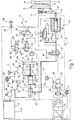
- Fig. 1 The in Fig. 1, the details of which are initially referred to be, overall designated 10 coupling device is designed for a heavy commercial vehicle that has a multi-stage, for example 16-stage, only schematically indicated change gear 11, the drive shaft 12 with the output shaft 13 of the vehicle engine, not shown, via a for the purpose of explanation as Diaphragm spring clutch with disengaged clutch 14 required coupling and can be uncoupled from it for performing switching operations.
- the vehicle it is further assumed that it has an electropneumatic circuit, in which the driver makes the choice of switching stages of the change-speed transmission 11, which appear to be favorable, by actuating a transmitter device 16, by means of whose command signals for upshifting, for downshifting and for reverse travel in an electronic control unit 17 can be entered, which automatically controls the automatic disengagement of the clutch 14 and changing the gear stages in the manner specified by the driver, as well as the engagement of the clutch again, so that the driver can handle the large number of gear changes without significant physical exertion, which ensure economically optimal operation of the Enable vehicle.
- a transmitter device 16 by means of whose command signals for upshifting, for downshifting and for reverse travel in an electronic control unit 17 can be entered, which automatically controls the automatic disengagement of the clutch 14 and changing the gear stages in the manner specified by the driver, as well as the engagement of the clutch again, so that the driver can handle the large number of gear changes without significant physical exertion, which ensure economically optimal operation of the Enable vehicle.
- a known electrically controllable switching device 18 required for changing the switching stages in the change gear 11 is only indicated schematically.
- a clutch actuator designated overall by 21, shown in dashed lines in FIG. 1, which acts as a control element, a hydraulic master cylinder 22 and as an actuator, acts on the clutch actuator 19
- Hydropneumatic power amplifier 23 includes, the actuating force is transmitted via an actuating plunger 24 to the power arm 19 'of the clutch actuator 19.
- the hydropneumatic booster 23 comprises a hydraulic slave cylinder 32 which can be coupled to the master cylinder 22 and a pneumatic drive cylinder which is combined with the slave cylinder 32 to form a structural unit 33 as a booster element and a proportional valve 36, controlled with the pressure prevailing in the drive pressure chamber 34 of the slave cylinder 32, as a control element by means of which the annular cylindrical drive pressure chamber 37 of the pneumatic drive cylinder coaxially surrounds the slave cylinder 32, and by means of the proportional valve 36 from the high outlet pressure of a pneumatic auxiliary pressure source 38 derived pressure proportional to the pressure prevailing in the drive pressure chamber 34 of the slave cylinder 32 can be coupled.
- the piston 39 of the slave cylinder 32 which axially movably delimits the drive pressure chamber 34 and the ring-cylindrical, pot-shaped piston 41 of the pneumatic drive cylinder 33 are firmly connected to one another and therefore engage together on the actuating plunger 24 of the clutch actuating device, which runs approximately coaxially with its central longitudinal axis 21 on.
- the clutch actuating device 21 comprises an emergency operation changeover valve 42 which, in the exemplary embodiment shown, is designed as a 3/2-way valve, which automatically controls the normal driving operation in which the actuation of the clutch 14 and the change of the gear stages 11 are assigned to excited position I, in which the output pressure chamber 26 of the motor-controlled master cylinder 22 with the drive pressure chamber 34 of the slave cylinder 32 of the power amplifier 23 are communicatively connected to one another via a first flow path 43 of this changeover valve 42, can be automatically switched back to its spring-centered basic position 0, in which the drive pressure chamber 34 of the slave cylinder 33 of the power amplifier can be switched back via an alternative flow path 44 to this emergency operation changeover valve 42 23 is connected to the pressure output 46 of an emergency operation control device, designated as a whole by 47, which also enables the clutch 14 to be engaged and disengaged by the driver if, for example, a failure of the electronic control unit 17 or a defect in the drive motor 28 des Master cylinder 22, the automatic switching operation is no longer possible, and the additional function
- the emergency operation control device 47 comprises a hydraulic master cylinder 49 which can be actuated by means of a pedal 48, the design of which with regard to the hydraulic oil volume displaceable from its outlet pressure chamber 51 corresponds to that of the motor-controlled master cylinder 26 of the clutch actuating device 21.
- a pressure converter designated overall by 52, which has a pneumatic inlet 53 to which a pressure relief valve 54, a protection valve 56 hydraulically connected in series and a protection type connected in series with it.
- Selector valve 57 can be connected to the pressure outlet 58 of the pneumatic auxiliary pressure source 38 and a hydraulic outlet 59 which, as an alternative to the pressure outlet 61 of the master cylinder 49 which can be actuated by means of the pedal 48, can be connected to the pressure outlet 46 of the emergency operation control device 47.
- the relevant - alternative - connection of the pressure outputs 59 and 61 of the pressure converter 52 or the pedal-operated master cylinder 49 is mediated by a pressure-controlled 3/2-way valve, an alternating check valve 62, which connects the pressure output 46 of the emergency operation control device 46 with that pressure output 59 or 61 connects the pressure converter 52 or the master cylinder 49 at which the higher outlet pressure prevails.
- the pressure converter 52 has - in the usual design - two piston flanges 64, 66 of different diameters D and d which are rigidly connected to one another by a piston rod 63 and which, in adjacent bore stages 67, 68, correspond to different diameters of the converter housing 69 are displaceably guided in a pressure-tight manner, the piston flange 64, which is larger in diameter, forming the axially movable boundary of the input chamber 71, and the piston piston 66, which is smaller in diameter, movably limits the - hydraulic - output chamber 72 of the pressure converter, which Check valve 62 can be connected to the pressure outlet 46 of the emergency operation control device 47.
- the two bore stages 67, 68 which connect to one another via a radial housing stage 73, are provided by an annular disk-shaped intermediate wall piece 74, which is inserted in the housing 69 in a liquid-tight manner and has a central bore through which the piston rod 63 of the converter piston 63, 64, 66 passes in a fluid-tight manner.
- This intermediate wall piece 74 forms the axially fixed limit of an axially movable limited by the smaller piston flange 66 trailing space 76, which is in permanent communication with an expansion tank 77, to the functionally corresponding compensation spaces 78,79 of the motor-controlled master cylinder 22 or by means of Emergency pedals 48 actuatable master cylinder 49 are permanently connected.
- the housing stage 73 and the annular disk-shaped intermediate wall piece 74 of the converter housing 69 form the fixed axial boundary of a media separation space 86 delimited axially movably within the bore stage 67 by the larger piston flange 64, which permanently relieves pressure, i.e. is vented to the ambient atmosphere and is also connected to the expansion tank 77 via a leak oil line, not shown.
- the hydraulic coupling of the power amplifier 23 of the clutch actuation device to the pressure output 46 of the emergency operation control device 47 mediating emergency operation switchover valve 42 and the protective valve 56 mediating the pneumatic control of the pressure converter 52 if necessary are designed as pressure-controlled, pneumatically actuated valves, the control chambers 87 and 88 of which, together with a control output 89 of an emergency operation control valve 91 provided for their electrical pilot control connected, the basic position 0 of which is assigned to emergency operation and whose functional position I, when its control magnet 92 is excited with an output signal from the electronic control unit 17, is assigned to the automatically running “normal” switching operation.
- the emergency operation control valve 91 is a 3/2-way solenoid valve which, in its - spring-centered - basic position 0, mediates the venting of the control chambers 87, 88 of the emergency operation changeover valve 42 and the protection valve 46 and blocks them against the pressure outlet 48 of the auxiliary pressure source 38 and in its excited position I via a flow path 93 in this connection connects the pressure outlet 58 of the pneumatic auxiliary pressure source 38 to the control chambers 87, 88 of the emergency operation switchover valve 42 and of the protective valve 46 and blocks it against the vent outlet 94 of the emergency operation control valve 91.
- the protective valve 56 is designed as a 3/2-way valve, which in its spring-centered basic position 0 has its control connection connected to the pressure limiting valve 54 96 connects to the control connection 97 of the protection type preselection valve 57 and blocks it against a vent outlet 98 of the protection valve 56 and, in the switching position I assumed when its control chamber 88 is pressurized, connects its control connection 96 to the venting outlet 98 and blocks it against the protection type preselection valve 57.
- the protective pre-selection valve 57 which is connected between the protective valve 56 and the pressure outlet 58 of the pneumatic auxiliary pressure source 38 in the exemplary embodiment shown, is designed as a bistable 3/2-way solenoid valve with two control windings 99 and 101, which can be controlled by brief electrical switching pulses from the electronic control unit 17 when only one control winding 99 is energized, it reaches its functional position I, in which its control output 97 is connected to a ventilation output 102 of the protection type preselection valve 57 and is blocked against the pressure output 58 of the auxiliary pressure source 38, and when its other control winding 101 is energized alone, into its functional position II arrives, in which the control outlet 97 of the protection type preselection valve 57 is connected to the pressure outlet 58 of the pneumatic auxiliary pressure source 38 and is shut off against the venting connection 102 of the protection type preselection valve.
- the protection type preselection valve has the property that after one of its two control windings 99 or 101 is energized temporarily or only briefly the associated functional position I or II is maintained until the other control winding 101 or 99 is energized.
- the protection type preselection valve 57 is controlled by output signals from the electronic control unit 17 in such a way that the protection type preselection valve 57 assumes its functional position I when and as long as the vehicle is moving at a speed v F that is greater than a threshold value v S and its Functional position II assumes when the vehicle speed is lower than the threshold value v S mentioned .
- a further control element of the emergency operation control device 47 is a position or displacement sensor 103, which is only indicated schematically and which responds to a change in position of the piston 81 of the master cylinder 49 which can be actuated by means of the emergency pedal 48 and which transmits the switch-off of the automatic switching operation of the electronic control unit 17 supplied output signal generates when and as long as the piston 81 of the master cylinder 49, which can be actuated by means of the emergency pedal 48, has disengaged from its largest volume corresponding to its initial position corresponding to its output pressure chamber 51.
- the emergency pedal 48 of the emergency operation control device 47 cannot be actuated in the normal, automatically controlled switching operation, so that the driver does not interrupt the normal — automatic — switching operation can, at least not accidentally.
- the emergency pedal 48 for example, as indicated by dashed lines, is held in a folded-up position during normal switching operation, for example in a niche in the driver's cab, in which it is not accessible for foot operation. It only reaches its position suitable for actuating the master cylinder 49 of the emergency operation control device 47 by releasing a lock, not shown, by automatic or manual means by the driver, after which the master cylinder can only be actuated by means of the pedal 48.
- the appropriate arrangement of the master cylinder 49 and the design of the pedal 48 in this regard are to be made from an ergonomic point of view and according to the spatial conditions in the driver's cab. It is only essential that the pedal 48 may only be actuated in the emergency mode of the clutch device 10.
- the drive pressure chamber 34 of the slave cylinder 32 of the power amplifier 23 is connected to the outlet pressure chamber 26 of the motor-controlled one via the flow path 43 released in the functional position I of the emergency operation switchover valve 42 Master cylinder 22 connected, the piston 27 still occupies an intermediate position between its minimum and maximum volume of the outlet pressure chamber 26 and moves towards the end position corresponding to the maximum volume of the outlet pressure chamber 26, whereby the volume of the outlet pressure chamber 26 increases and hydraulic oil from the slave cylinder 32 of the booster 23 flows to the master cylinder 22, from whose compensation space 78 hydraulic oil is displaced into the expansion tank 77.
- the valve reaches its venting position II, in which the pressure in the pneumatic drive cylinder 33 of the power amplifier 23 is reduced.
- the output pressure of the pneumatic auxiliary pressure source 38 now present at the control connection 96 of the protective valve 56 is via the pressure limiting valve 54 into the input chamber 71 of the pressure converter 52 up to that through the pressure limiting valve 54 defined amount can be coupled in, whereby pressure is built up in the - hydraulic - output chamber 72, which via the change-over check valve 62 to the pressure outlet 46 of the emergency operation control device 47 and via the flow path 44 released into the slave cylinder in the basic position 0 of the emergency operation change-over valve 42 32 of the booster 23 and the hydraulic control circuit of the proportional valve 36 is coupled, which thereby reaches its pressure build-up position I, in which the pressure output 58 of the pneumatic auxiliary pressure source 38 also in the drive pressure chamber 37 of the pneumatic drive cylinder 33 of the power amplifier 23 can be coupled, which is now controlled in the sense of disengaging the clutch 14.
- the protective function achieved according to this consists in interrupting the drive train of the vehicle at a
- the driver is informed of the emergency situation by an optical and / or an acoustic signal and if necessary, a lock holding the emergency pedal 48 in its non-actuatable position is lifted at the same time, so that the driver can bring the emergency pedal 48 into it if it does not automatically reach the usable position and can now use it to release the clutch 14.
- the piston arrangement 63, 64, 66 of the pressure converter 52 can now carry out the retraction movement, which returns to the end position corresponding to the maximum volume of the outlet chamber 72.
- a compensating check valve 106 is provided, which is acted upon by the relatively higher pressure in the compensating tank 77 of the hydraulic circuit of the coupling device 10 than in the outlet chamber 72 of the pressure converter 52 in the opening direction and is otherwise blocking, the flow path which can be released by this check valve 106 being in the bottom part of the Housing bore 68 of the pressure converter 52 opens into its output chamber 72, ie in an area thereof which is not blocked off by its piston arrangement 66, 63, 64 even in the minimum volume of the output chamber 72 of the pressure converter 52.
- the pressure developed in the master cylinder 49 which can be actuated by means of the emergency pedal 48, is coupled into the slave cylinder 32 of the power amplifier 23 via the emergency mode switchover valve 42 in its basic position 0 and also acts on the proportional valve 36 via the hydraulic control line 107, which thereby results in its functional position II arrives, in which the pressure outlet 58 of the pneumatic auxiliary pressure source 8 also enters the drive pressure chamber 97 of the pneumatic drive cylinder 33 of the power amplifier 23 to amplify the clutch 14 which disengages Actuating force is coupled.
- the clutch 14 is disengaged, which can now engage the shift stage of the transmission 11 which he considers appropriate by actuating the transmitter device 16 and can control the engagement of the clutch 14 again by withdrawing the emergency pedal 48.
- the interchangeable check valve 62 remains in its functional position which enables the passage from the slave cylinder 32 of the power amplifier 23 of the clutch actuating device 21 to the output pressure chamber 51 of the pedal-controlled master cylinder 49 at least until hydraulic oil is returned to the compensating tank 77 via the compensating flow path 83 Output pressure chamber 51 of the master cylinder 49 which can be actuated by means of the emergency pedal 48 can flow.
- the emergency operation control valve 91 and the protective valve 56 actuated via this and the emergency operation switchover valve 42 assume their switching positions I.
- the protection type preselection valve 57 is in its functional position I, the venting position.
- the input chamber 71 of the pressure converter 52 is kept depressurized via the pressure limiting valve 54 and the protective valve 56 located in its venting position I, with the result that the piston arrangement 66, 63, 64 of the pressure converter 52 assumes its basic position linked to the greatest volume of its hydraulic output chamber 72.
- the electric drive motor 28 of the master cylinder 22 is driven in the direction of rotation in such a way that the piston 27 of the master cylinder 22 of the clutch actuating device 21 moves in the sense of a reduction in the output pressure space 26 of this master cylinder 22, which via the emergency mode changeover valve 42 in its functional position I Hydraulic oil to the slave cylinder 32 delivers, which in the drive pressure chamber 34 of the slave cylinder 32 of the booster 23 prevailing pressure, which also prevails at the hydraulic control connection 108 of the proportional valve 36 of the booster 23, which thereby assumes an equilibrium position which corresponds functionally to its functional position II, in which a pneumatic pressure proportional to this hydraulic pressure, which by means of the proportional valve 36 from Output pressure of the pneumatic auxiliary pressure source 38 is derived, is also coupled into the drive pressure chamber 37 of the pneumatic drive cylinder 33 of the power amplifier 23 which pivots the clutch actuator 19 in the sense of disengaging the clutch 14 via the actuating plunger 24.
- the emergency operation control device 47 in such a way that the drive train of the vehicle remains closed, ie, for example when driving downhill, the braking effect of the engine is maintained in overrun mode.
- the drive comprising the electric motor 28, for example a spindle drive, of the master cylinder 22 of the clutch actuating device 21 is self-locking, so that after the electronic control unit is switched off and the resultant drop the control of the drive motor 28 of the pistons 27 of the master cylinder 22 remains in its position assumed when the control signal for its drive motor 28 drops.
- the driver can now, after the emergency pedal 48 is released for the emergency actuation, by actuating the master cylinder 49 of the emergency operation control device 47, pressure in the slave cylinder 32 and on the hydraulic control connection 108 of the proportional valve 36 of the booster 23 and thus also in the pneumatic drive cylinder 33 of the booster 23 build up and disassemble in a targeted manner and thereby control the disengagement and engagement movements of the clutch 14 required for performing switching operations, as already described with reference to the first malfunction example.
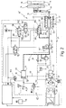
- FIG. 2 a coupling device 10 that is functionally equivalent to the coupling device 10 according to FIG. 1 is designated as a whole by 10 ′, which is significantly simplified compared to the coupling device 10 by a Structure distinguishes, the structural simplification - essentially - consists in that a pressure converter is not required for emergency operation and the functional difference that enables this saving is that in emergency operation of the coupling device 10 ', ie in the event of a malfunction thereof, the output pressure of the pneumatic auxiliary pressure source 38, as it were, directly via the protective valve 56 in its basic position 0 in this case, the protection type preselection valve 57, provided that it is in its functional position II and the proportional valve 36 in its basic position I into the pneumatic drive pressure chamber 37 of the - To this extent modified - power amplifier 23 of the clutch actuating device 21 can be coupled.
- the electrically controlled emergency operation control valve 91 falls back into its basic position 0 - its venting position -, as a result of which the protective valve 56 and the emergency operation changeover valve 42 are also switched back to their basic positions 0.
- the protection valve 56 and the protection type preselection valve located in its functional position II in which the control connection 96 of the protection valve 56 with the control connection 97 of the protection type preselection valve 57 and this via the proportional valve 36 'located in its functional position I with the drive pressure chamber 37 of the pneumatic Drive cylinder 33 of the booster 23 'of the clutch actuation device 21 is connected, the output pressure of the auxiliary pressure source 38 is coupled into the pneumatic drive cylinder 33 of the booster 23' and into the pneumatic control chamber 109 of the proportional valve 36 ', whereby on the one hand the booster 23' in the sense disengagement of the clutch 14 is actuated and on the other hand the proportional valve 36 'is held in its functional position I; furthermore, by switching the emergency operation switchover valve 42 back into its
- the by the emergency operation control device 47 'in The protective function imparted to the described fault situation consists in the fact that, as also in the exemplary embodiment according to FIG. 1, the clutch 14 changes into the disengaged state which is regarded as appropriate for the situation - safely.
- the driver In order to set the clutch device 10 'to emergency operation, the driver must first press the pedal 48, the readiness for which is signaled by the output signal of a position switch 113, in the sense of a pressure build-up in the output pressure chamber 51 of the master cylinder 49 which can be actuated by means of the pedal 48.
- the hydraulic oil displaced from the outlet pressure chamber 51 of the master cylinder 49 which cannot be taken up by the slave cylinder 32, since it has already taken up the largest possible amount of hydraulic oil, passes through a pressure relief valve 115 connected in parallel to the check valve 111 to the pressureless expansion tank 77 achieved displacement of the piston 81 of the master cylinder 49 triggers an output signal of the position sensor 103 from a minimum stroke of the piston 81, by means of which the protection type preselection valve 57 is switched to its functional position I - its venting position - in which the drive pressure chamber 37 of the pneumatic drive cylinder 33 des Power amplifier 23 'can be vented via the proportional valve 36' and the vent outlet 102 of the protection type preselection valve 57.
- the driver can engage the desired gear stage of the transmission 11 if this has not already been engaged and has remained engaged before the malfunction occurred.
- the clutch device 10 'according to FIG. 2 is now — as it were “finally” - prepared for emergency operation, for which the protection type preselection valve 57 remains in the switching position I corresponding to normal operation of the vehicle at high vehicle speed and the clutch disengages in the - "accustomed” way is controllable in that the driver depresses the emergency pedal 48 and the disengagement of the clutch 14 is controlled by withdrawing the emergency pedal 48, in which emergency operation the piston 81 of the master cylinder 49 actuable by means of the pedal 48, its entire, between its executes possible stroke in both end positions.
- the protection type preselection valve 57 is thus in its functional position I. and the emergency mode switchover valve 42 are in their normal operating position I and the piston 27 of the motor-controlled master cylinder 22 executes its hydraulic oil to the slave cylinder 22 displacing stroke, whereby the proportional valve 36 'is controlled via its hydraulic control path 107 into an equilibrium position corresponding to the functional position II and accordingly the pneumatic drive cylinder 33 of the power amplifier 23' in the sense of disengaging the clutch 14 is acted upon by pneumatic auxiliary pressure.
- the piston 81 of the master cylinder 49 of the emergency operation control device 47 ' is in its basic position, in which the outlet pressure chamber 51 of this master cylinder 49 is communicatively connected to the expansion tank 77 of the clutch device 10'.
- the protective effect imparted by the emergency operation control device 47 'in this situation thus consists in the clutch transitioning into the engaged state, which is considered "safe”.
- the coupling device 10 ' is then prepared from the outset for emergency operation with the usual movement sequence of the actuating movements, without the driver having to carry out any further preparatory actuation of the pedal 48.
Landscapes
- Engineering & Computer Science (AREA)
- Chemical & Material Sciences (AREA)
- Combustion & Propulsion (AREA)
- Transportation (AREA)
- Mechanical Engineering (AREA)
- Hydraulic Clutches, Magnetic Clutches, Fluid Clutches, And Fluid Joints (AREA)
Applications Claiming Priority (2)
| Application Number | Priority Date | Filing Date | Title |
|---|---|---|---|
| DE4439447 | 1994-11-04 | ||
| DE4439447A DE4439447C1 (de) | 1994-11-04 | 1994-11-04 | Notkuppeleinrichtung |
Publications (2)
| Publication Number | Publication Date |
|---|---|
| EP0710580A1 true EP0710580A1 (fr) | 1996-05-08 |
| EP0710580B1 EP0710580B1 (fr) | 1998-06-17 |
Family
ID=6532495
Family Applications (1)
| Application Number | Title | Priority Date | Filing Date |
|---|---|---|---|
| EP95114437A Expired - Lifetime EP0710580B1 (fr) | 1994-11-04 | 1995-09-14 | Dispositif d'embrayage d'urgence |
Country Status (2)
| Country | Link |
|---|---|
| EP (1) | EP0710580B1 (fr) |
| DE (2) | DE4439447C1 (fr) |
Cited By (5)
| Publication number | Priority date | Publication date | Assignee | Title |
|---|---|---|---|---|
| DE19723362A1 (de) * | 1997-06-04 | 1998-12-10 | Mannesmann Sachs Ag | Notbetätigung für eine automatisch betätigte Kraftfahrzeugkupplung |
| US6290045B1 (en) | 1998-12-17 | 2001-09-18 | Wabco Gmbh | Actuating mechanism for a clutch |
| DE102005039922A1 (de) * | 2005-08-24 | 2007-03-08 | Zf Friedrichshafen Ag | Einrichtung zum Betätigen einer Membranfederkupplung für Fahrzeuge |
| DE102006035134A1 (de) * | 2006-07-29 | 2008-01-31 | Zf Friedrichshafen Ag | Kupplungssystem |
| CN105163993A (zh) * | 2013-02-28 | 2015-12-16 | 依维柯马基路斯公司 | 用于防止设置有离合器伺服机构和伺服换挡致动的变速箱系统的车辆的变速箱损坏的系统 |
Families Citing this family (8)
| Publication number | Priority date | Publication date | Assignee | Title |
|---|---|---|---|---|
| DE19632807C2 (de) * | 1996-08-16 | 1998-07-02 | Daimler Benz Ag | Verfahren zur selbsttätigen Steuerung einer im Antriebsstrang eines Kraftfahrzeuges im Kraftfluß zwischen einem Antriebsmotor und einem Stufengetriebe angeordneten Kupplung |
| DE19849488C2 (de) | 1998-10-27 | 2000-11-30 | Mannesmann Sachs Ag | Hydraulische Betätigungseinrichtung zur Betätigung einer Reibungskupplung und eines automatisierten Schaltgetriebes |
| DE19937379A1 (de) * | 1999-08-07 | 2001-01-04 | Daimler Chrysler Ag | Vorrichtung zur Erfassung der Kupplungsstellung |
| DE10230774A1 (de) * | 2002-07-09 | 2004-01-22 | Zf Friedrichshafen Ag | Steuersystem für ein Anfahrschaltelement eines automatisierten Getriebes oder Automatgetriebes im Notbetrieb |
| DE102007044431A1 (de) | 2007-09-18 | 2009-03-19 | Zf Friedrichshafen Ag | Elektrohydraulische Steuerungsvorrichtung |
| DE102009052710A1 (de) * | 2009-11-11 | 2011-05-12 | GM Global Technology Operations LLC, Detroit | Vorrichtung zum mechanischen Ausrücken einer automatisch eingerückten Kupplungseinrichtung |
| KR101336942B1 (ko) * | 2011-11-24 | 2013-12-04 | 원광이엔텍 주식회사 | 클러치 제어 장치 |
| CN107387593A (zh) * | 2017-09-02 | 2017-11-24 | 吉林大学 | 电机直驱式离合器电控液压执行机构及其控制方法 |
Citations (4)
| Publication number | Priority date | Publication date | Assignee | Title |
|---|---|---|---|---|
| DE2856150A1 (de) * | 1977-12-30 | 1979-07-19 | Autoipari Kutato Intezet | Steuereinrichtung zum betaetigen einer fahrzeug-reibungskupplung |
| FR2611837A1 (fr) * | 1987-02-26 | 1988-09-09 | Valeo | Dispositif de commande d'embrayage avec pilotage |
| EP0516309A2 (fr) * | 1991-05-25 | 1992-12-02 | Massey Ferguson S.A. | Embrayages |
| GB2258283A (en) * | 1991-07-30 | 1993-02-03 | Fichtel & Sachs Ag | Pneumatic/hydraulic arrangement for operating,in an emergency,a friction clutch of a motor vehicle |
-
1994
- 1994-11-04 DE DE4439447A patent/DE4439447C1/de not_active Expired - Fee Related
-
1995
- 1995-09-14 DE DE59502583T patent/DE59502583D1/de not_active Expired - Fee Related
- 1995-09-14 EP EP95114437A patent/EP0710580B1/fr not_active Expired - Lifetime
Patent Citations (4)
| Publication number | Priority date | Publication date | Assignee | Title |
|---|---|---|---|---|
| DE2856150A1 (de) * | 1977-12-30 | 1979-07-19 | Autoipari Kutato Intezet | Steuereinrichtung zum betaetigen einer fahrzeug-reibungskupplung |
| FR2611837A1 (fr) * | 1987-02-26 | 1988-09-09 | Valeo | Dispositif de commande d'embrayage avec pilotage |
| EP0516309A2 (fr) * | 1991-05-25 | 1992-12-02 | Massey Ferguson S.A. | Embrayages |
| GB2258283A (en) * | 1991-07-30 | 1993-02-03 | Fichtel & Sachs Ag | Pneumatic/hydraulic arrangement for operating,in an emergency,a friction clutch of a motor vehicle |
Non-Patent Citations (2)
| Title |
|---|
| ANTRIEBSTECHNIK, March 1992 (1992-03-01), pages 52 FF |
| BADER C: "ELEKTRONISCHE ANTRIEBSSTEUERUNG FÜR NUTZFAHRZEUGE", VDI Z, vol. 134, no. SPECIAL, 1 March 1992 (1992-03-01), DÜSSELDORF, DE, pages 52 - 68, XP000297808 * |
Cited By (8)
| Publication number | Priority date | Publication date | Assignee | Title |
|---|---|---|---|---|
| DE19723362A1 (de) * | 1997-06-04 | 1998-12-10 | Mannesmann Sachs Ag | Notbetätigung für eine automatisch betätigte Kraftfahrzeugkupplung |
| DE19723362C2 (de) * | 1997-06-04 | 2002-07-18 | Zf Sachs Ag | Notbetätigung für eine automatisch betätigte Kraftfahrzeugkupplung |
| US6290045B1 (en) | 1998-12-17 | 2001-09-18 | Wabco Gmbh | Actuating mechanism for a clutch |
| DE102005039922A1 (de) * | 2005-08-24 | 2007-03-08 | Zf Friedrichshafen Ag | Einrichtung zum Betätigen einer Membranfederkupplung für Fahrzeuge |
| US8002100B2 (en) | 2005-08-24 | 2011-08-23 | Zf Friedrichshafen Ag | Device for actuating a diaphragm spring clutch for vehicles |
| DE102006035134A1 (de) * | 2006-07-29 | 2008-01-31 | Zf Friedrichshafen Ag | Kupplungssystem |
| US8187148B2 (en) | 2006-07-29 | 2012-05-29 | Zf Friedrichshafen Ag | Clutch system |
| CN105163993A (zh) * | 2013-02-28 | 2015-12-16 | 依维柯马基路斯公司 | 用于防止设置有离合器伺服机构和伺服换挡致动的变速箱系统的车辆的变速箱损坏的系统 |
Also Published As
| Publication number | Publication date |
|---|---|
| DE59502583D1 (de) | 1998-07-23 |
| EP0710580B1 (fr) | 1998-06-17 |
| DE4439447C1 (de) | 1996-03-14 |
Similar Documents
| Publication | Publication Date | Title |
|---|---|---|
| EP2047133B1 (fr) | Système d'accouplement | |
| EP1067319B2 (fr) | Dispositif de commande pour actionneur de transmission | |
| EP2754911B1 (fr) | Dispositif hydraulique d'actionnement pour la commande d'au moins un embrayage a friction et d'au moins une boite de vitesse dans un véhicule | |
| DE4125162A1 (de) | Anordnung zur betaetigung einer reibungskupplung eines kraftfahrzeugs, insbesondere eines lastkraftwagens | |
| DE102007024794A1 (de) | Verfahren und Einrichtung zum Steuern des Einrückgrades einer automatischen oder automatisierten Kraftfahrzeugkupplung | |
| DE4439447C1 (de) | Notkuppeleinrichtung | |
| DE29714652U1 (de) | Stellantrieb mit Ventileinheiten zur Betätigung einer Reibungskupplung und eines automatisierten Schaltgetriebes | |
| WO2015113744A1 (fr) | Dispositif d'actionnement hydraulique d'un embrayage à friction de véhicule automobile | |
| DE3636260C2 (fr) | ||
| WO2008071392A2 (fr) | Dispositif et procédé de récupération d'énergie | |
| DE102004033362A1 (de) | Hydraulikkreis für ein Doppelkupplungsgetriebe | |
| EP1199233A2 (fr) | Dispositif de commande pour un frein de stationnement pour véhicule automobile | |
| EP3446005A1 (fr) | Procédé pour faire fonctionner un dispositif de frein de parking au moyen d'un système hydraulique | |
| DE69937115T2 (de) | Verfahren zum steuern des hydraulikdrucks in schaltgetrieben mit hydraulischen kupplungen | |
| DE102015225057A1 (de) | Verfahren zum Betreiben einer elektronisch schlupfregelbaren Fremdkraftbremsanlage und Elektronisch schlupfregelbare Fremdkraftbremsanlage | |
| EP3446004A1 (fr) | Procédé pour faire fonctionner un dispositif de frein de parking au moyen d'un système hydraulique | |
| DE102015226568A1 (de) | Elektronisch schlupfregelbare Fremdkraftbremsanlage | |
| EP3728905B1 (fr) | Système de soupapes pour une fonction hydraulique de marche d'urgence d'une transmission automatique de véhicule automobile | |
| DE4439448C1 (de) | Notkuppeleinrichtung | |
| DE102009031742A1 (de) | Fahrbare Arbeitsmaschine mit einer als Betriebsbremse und als automatische Feststellbremse betreibbaren Bremse | |
| EP1271008B1 (fr) | Dispositif de commande pour transmissions véhiculaires automatisées partiellement ou automatiques | |
| DE19815666B4 (de) | Verfahren zum Betreiben eines Stellantriebs zur automatisierten Betätigung einer Reibungskupplung und eines automatisierten Schaltgetriebes | |
| EP1938003B1 (fr) | Dispositif de soupapes de commande pour la commande d'un embrayage de demarrage d'une boite de vitesses automatique | |
| DE102020205759B3 (de) | Hydraulikkreis für ein Doppelkupplungsgetriebe sowie ein Verfahren zum Betreiben des Hydraulikkreises | |
| DE3732427A1 (de) | Einrichtung zur unterdrueckung von laengsschwingungen an einem fahrzeug mit schaltgetriebe |
Legal Events
| Date | Code | Title | Description |
|---|---|---|---|
| PUAI | Public reference made under article 153(3) epc to a published international application that has entered the european phase |
Free format text: ORIGINAL CODE: 0009012 |
|
| AK | Designated contracting states |
Kind code of ref document: A1 Designated state(s): DE FR IT SE |
|
| 17P | Request for examination filed |
Effective date: 19960329 |
|
| 17Q | First examination report despatched |
Effective date: 19970120 |
|
| RAP1 | Party data changed (applicant data changed or rights of an application transferred) |
Owner name: DAIMLER-BENZ AKTIENGESELLSCHAFT |
|
| GRAG | Despatch of communication of intention to grant |
Free format text: ORIGINAL CODE: EPIDOS AGRA |
|
| GRAG | Despatch of communication of intention to grant |
Free format text: ORIGINAL CODE: EPIDOS AGRA |
|
| GRAH | Despatch of communication of intention to grant a patent |
Free format text: ORIGINAL CODE: EPIDOS IGRA |
|
| GRAH | Despatch of communication of intention to grant a patent |
Free format text: ORIGINAL CODE: EPIDOS IGRA |
|
| GRAA | (expected) grant |
Free format text: ORIGINAL CODE: 0009210 |
|
| ITF | It: translation for a ep patent filed | ||
| AK | Designated contracting states |
Kind code of ref document: B1 Designated state(s): DE FR IT SE |
|
| REF | Corresponds to: |
Ref document number: 59502583 Country of ref document: DE Date of ref document: 19980723 |
|
| ET | Fr: translation filed | ||
| RAP2 | Party data changed (patent owner data changed or rights of a patent transferred) |
Owner name: DAIMLERCHRYSLER AG |
|
| PLBE | No opposition filed within time limit |
Free format text: ORIGINAL CODE: 0009261 |
|
| STAA | Information on the status of an ep patent application or granted ep patent |
Free format text: STATUS: NO OPPOSITION FILED WITHIN TIME LIMIT |
|
| 26N | No opposition filed | ||
| PGFP | Annual fee paid to national office [announced via postgrant information from national office to epo] |
Ref country code: SE Payment date: 20000825 Year of fee payment: 6 |
|
| PGFP | Annual fee paid to national office [announced via postgrant information from national office to epo] |
Ref country code: FR Payment date: 20000831 Year of fee payment: 6 |
|
| PG25 | Lapsed in a contracting state [announced via postgrant information from national office to epo] |
Ref country code: SE Free format text: LAPSE BECAUSE OF NON-PAYMENT OF DUE FEES Effective date: 20010915 |
|
| EUG | Se: european patent has lapsed |
Ref document number: 95114437.7 |
|
| PG25 | Lapsed in a contracting state [announced via postgrant information from national office to epo] |
Ref country code: FR Free format text: LAPSE BECAUSE OF NON-PAYMENT OF DUE FEES Effective date: 20020531 |
|
| REG | Reference to a national code |
Ref country code: FR Ref legal event code: ST |
|
| PGFP | Annual fee paid to national office [announced via postgrant information from national office to epo] |
Ref country code: DE Payment date: 20040907 Year of fee payment: 10 |
|
| PG25 | Lapsed in a contracting state [announced via postgrant information from national office to epo] |
Ref country code: IT Free format text: LAPSE BECAUSE OF NON-PAYMENT OF DUE FEES;WARNING: LAPSES OF ITALIAN PATENTS WITH EFFECTIVE DATE BEFORE 2007 MAY HAVE OCCURRED AT ANY TIME BEFORE 2007. THE CORRECT EFFECTIVE DATE MAY BE DIFFERENT FROM THE ONE RECORDED. Effective date: 20050914 |
|
| PG25 | Lapsed in a contracting state [announced via postgrant information from national office to epo] |
Ref country code: DE Free format text: LAPSE BECAUSE OF NON-PAYMENT OF DUE FEES Effective date: 20060401 |