EP0710846B1 - Dispositif pour générer un signal représentatif de la distorsion harmonique totale d'un système électrique à courant alternatif - Google Patents
Dispositif pour générer un signal représentatif de la distorsion harmonique totale d'un système électrique à courant alternatif Download PDFInfo
- Publication number
- EP0710846B1 EP0710846B1 EP95116899A EP95116899A EP0710846B1 EP 0710846 B1 EP0710846 B1 EP 0710846B1 EP 95116899 A EP95116899 A EP 95116899A EP 95116899 A EP95116899 A EP 95116899A EP 0710846 B1 EP0710846 B1 EP 0710846B1
- Authority
- EP
- European Patent Office
- Prior art keywords
- signal
- digital
- generating
- fundamental
- waveform
- Prior art date
- Legal status (The legal status is an assumption and is not a legal conclusion. Google has not performed a legal analysis and makes no representation as to the accuracy of the status listed.)
- Expired - Lifetime
Links
- 238000005070 sampling Methods 0.000 claims description 20
- 238000004364 calculation method Methods 0.000 description 10
- 238000000034 method Methods 0.000 description 6
- 230000007935 neutral effect Effects 0.000 description 4
- 238000010586 diagram Methods 0.000 description 2
- 238000012545 processing Methods 0.000 description 2
- 230000002411 adverse Effects 0.000 description 1
- 238000004422 calculation algorithm Methods 0.000 description 1
- 238000006243 chemical reaction Methods 0.000 description 1
- 238000013329 compounding Methods 0.000 description 1
- 238000004590 computer program Methods 0.000 description 1
- 239000004020 conductor Substances 0.000 description 1
- 238000013480 data collection Methods 0.000 description 1
- 238000000354 decomposition reaction Methods 0.000 description 1
- 230000001419 dependent effect Effects 0.000 description 1
- 238000001514 detection method Methods 0.000 description 1
- 230000000694 effects Effects 0.000 description 1
- 238000005259 measurement Methods 0.000 description 1
- 238000012986 modification Methods 0.000 description 1
- 230000004048 modification Effects 0.000 description 1
- 238000012544 monitoring process Methods 0.000 description 1
- 230000000737 periodic effect Effects 0.000 description 1
- 230000001360 synchronised effect Effects 0.000 description 1
Images
Classifications
-
- G—PHYSICS
- G01—MEASURING; TESTING
- G01R—MEASURING ELECTRIC VARIABLES; MEASURING MAGNETIC VARIABLES
- G01R23/00—Arrangements for measuring frequencies; Arrangements for analysing frequency spectra
- G01R23/16—Spectrum analysis; Fourier analysis
- G01R23/20—Measurement of non-linear distortion
Definitions
- This invention relates to harmonic distortion analysis of waveforms in an AC electrical system and, in particular, to an apparatus by which a total harmonic distortion signal of reasonable accuracy can be repetitively generated without undue signal processing.
- Harmonic analysis is based on the principal that any periodic waveform can be characterized as the sum of a sine wave at the fundamental frequency and sine waves at harmonics of the fundamental frequency.
- One standard measure of harmonic distortion is individual harmonic distortion. This is a measure of the distortion attributable to a specific harmonic. Individual harmonic distortion is measured as the RMS value of the particular harmonic as a percentage of the RMS value of the fundamental frequency.
- Another standard measure of harmonic distortion is the total harmonic distortion. Typically, total harmonic distortion is calculated as the ratio of the square root of the sum of the squares of the RMS values of the individual harmonics not including the fundamental to the RMS value of the fundamental converted to a percentage.
- the typical total harmonic calculation requires calculation of the individual harmonics.
- the values of the harmonics and the fundamental frequency component can be extracted from digital samples of the AC waveform by use of Fourier analysis. This analysis produces sine and cosine coefficients for the fundamental and each of the harmonics to be analyzed.
- This analysis produces sine and cosine coefficients for the fundamental and each of the harmonics to be analyzed.
- Compounding the problem is the fact that a waveform must be digitally sampled at twice the frequency of the highest harmonic to be extracted. Therefore, in order to extract the fiftieth harmonic from a waveform with 60 Hz fundamental frequency, sampling must be performed at 6KHz.
- analyzers must have processors which can sample at the high sampling rate needed to extract the desired harmonics, and can also perform the extensive calculations required for the Fourier analysis. Typically, analyzers sample for one or a few cycles and then suspend sampling while the harmonic coefficients are calculated. This technique degrades the ability of the analyzer to catch transients in the waveforms. Some analyzers trigger the high speed sampling required for harmonic analysis upon detection of specific events, thereby capturing the portion of the waveform of interest.
- an apparatus for generating a signal representative of total harmonic distortion in an AC wave form and an apparatus for determining the total harmonic distortion in a wave form of an AC power distribution system is provided.
- Preferred embodiments of the invention are disclosed in the dependent claims.
- the invention is directed to apparatus for approximating the total harmonic distortion (THD) in an AC waveform from the RMS value of the signal minus its fundamental component. More particularly, the instantaneous value of the fundamental component of the signal is calculated and subtracted from the instantaneous value of the signal. The RMS value of that difference is then calculated, divided by the RMS value of the fundamental and converted to a percentage to produce the approximation of the THD.
- THD total harmonic distortion
- means are provided for generating a sensed signal which is representative of the AC waveform.
- Means are also provided for generating from the sensed signal a fundamental signal representative of the fundamental frequency component of the sensed signal. Additional means generate a harmonics signal as a difference between the sensed signal and the fundamental signal. Means then generate a total harmonic distortion signal from the harmonic signal and the fundamental frequency signal. More particularly, the latter means includes means which generates the RMS value of the harmonic signal and divides it by the RMS value of the fundamental frequency signal and converts the quotient to a percentage.
- the invention is carried out by a digital system which generates digital samples of the waveform, determines the fundamental frequency component for each sample, and subtracts that fundamental frequency component from the digital sample value to generate a digital harmonic signal.
- the RMS value of this digital harmonic signal is then determined and divided by the RMS value of the fundamental frequency component.
- THD Transform of a THD signal in accordance with the invention is more accurate than the approximation technique described above. If the harmonic signal is maintained to an accuracy of 1/2% of the RMS value of the signal, THD values should be accurate to about 1%. Thus, this technique is more tolerant of sampling and timing errors than the approximate "technique" described in the background, however, it requires more calculation steps or about twice the execution time. On the other hand, this technique requires much less execution time than is needed for calculating the "exact” THD, e.g., 1/25 of the execution time where 50 harmonics are used in the "exact” calculation.
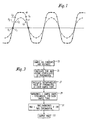
- an AC waveform W is shown which is somewhat squared indicating that it has significant harmonic content.
- the waveform is sampled at sample points S equally spaced in time.
- the waveform is sampled at a rate at least twice the frequency of the highest harmonic to be detected in order to satisfy the Nyquist criteria.
- sampling would be carried out at least 6 KHz in order to extract up to the 50th harmonic. That would mean that 100 samples per cycle of a 60 Hz signal would have to be taken to extract the 50th harmonic.
- the THD calculations are made from samples taken at 32 samples per cycle of the 60 Hz waveform W. For purposes of clarity of illustration, however, a fewer number of samples per cycle are shown in Figure 1. Also, it should be noted that in Figure 1 samples are shown taken at the zero crossings of the waveform W. This is not necessary. It is necessary, however, that the sampling be synchronous. That is, an integer number of samples should be taken per cycle. This is necessary in order to perform a Fourier analysis. This well known mathematical technique is used to produce a sine and a cosine coefficient for the fundamental frequency component F of the waveform W. These coefficients are used to calculate from the samples S 1 , S 2 , ... S n taken of the waveform W, the corresponding values of each of the sample points of the fundamental frequency component F of the waveform W. These calculated values of the fundamental frequency component are indicated by the reference characters C 1 to C n .
- a digital signal H representing the harmonics is generated by taking the difference between the measured sampled values of the waveform W and the calculated value of the fundamental component.
- the total harmonic distortion is then calculated as the RMS value of this digital harmonic signal H divided by the RMS value of the fundamental frequency component F.
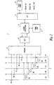
- FIG. 2 illustrates a monitor/analyzer 1 which can be used to generate a THD output in accordance with the invention.
- the monitor/analyzer 1 is shown connected to an AC electric power system 3 such as a power distribution system for analyzing waveforms in the system.
- a ranging circuit 11 converts the current and the voltage signals from -10 to 0 to +10 volt signals for conversion by analog to digital (A/D) converter 13 for input to a digital processor 15.
- the A/D converter 13 samples the analog voltages and currents at sampling rates determined by interrupts generated by the digital processor 15. These interrupts are generated selectively at a first, slow speed sampling rate, or a second, high speed sampling rate.
- the slow speed sampling rate is 32 samples per cycle and the high speed rate is 128 samples per cycle.
- the A/D converter 13 samples all five currents and all four voltages. For high speed sampling, again all currents are sampled, but only the three phase voltages are digitized for input to the processor. Each of these currents and voltages is sampled on each interrupt.
- the digital processor 15 utilizes the data generated by these digital samples to generate values of two sets of electrical parameters.
- the first set of parameters is related to the monitoring function and includes metered parameters such as: RMS currents and voltages, peak currents and voltages, minimum currents and voltages, power factor, watts, Vars, volt-amps, total harmonic factor, K-factor, CBMEA derating factor, and the like.
- the second set of parameters calculated by the digital processor 15 are the individual harmonic coefficients.
- the present invention organizes data collection and processing so that a maximum number of parameters can be monitored continuously while also providing the capability for simultaneous calculation of harmonic content.
- the digital processor 15 has an input/output (I/O) 17 through which the processor 15 is connected to a front panel 19.
- the front panel 19 serves as the interface with the user. It is through the front panel that the user can control the operation of the monitor/analyzer 1 and monitor the AC electrical power system 3.
- the input/output device 17 also interfaces the digital processor 15 with contact inputs through a digital input. Relay outputs and analog outputs are also provided through the input/output device 17.
- the digital processor 15 can also communicate with a remote processor through a communications link 21. Through this communications link 21 the monitor/analyzer 1 can provide information to and/or be controlled by a remote processor (not shown).
- the THD output of the monitor/analyzer 1 can be a numerical readout on the front panel 19. In addition, or instead, the THD output can be communicated to a remote device over the communications link 21. It will be appreciated that the monitor/analyzer 1 can also, if desired, determine the individual harmonic content of waveforms in the distribution system 3. This is described in the cross-referenced patent application.
- the analyzer switches to a faster sampling rate, 128 samples per cycle in the exemplary analyzer, in order to have data appropriate for calculating up to the 50th harmonic. That analyzer uses a sampling scheme in which samples are normally taken at 32 samples per cycle, but samples can be taken at 128 samples per cycle for two consecutive cycles out of each eight cycles.
- FIG. 3 illustrates a flow chart of a routine used by the processor 15 in order to generate the THD output.
- samples are taken 32 times per cycle of all 5 currents and 4 line to neutral voltages (line to line voltages are line to neutral voltages, as is well known).
- the sine and cosine coefficients of the fundamental component of each of the currents and voltages are then calculated at 25 using Fourier analysis, as is also well known. These coefficients are then used at 27 to calculate the instantaneous value of the fundamental of each of the waveforms at each of the sample points. This value of the fundamental of each of the waveforms at each of the sample points is then subtracted from the measured value of the waveform at 29 to generate the harmonic signal.
- These harmonic signals and the fundamental components are then used to calculate the THD values for each of the currents and voltages in accordance with the above Equation 1.
- These THD values are then output at 33 for presentation to the user of the analyzer/monitor.
Landscapes
- Physics & Mathematics (AREA)
- Nonlinear Science (AREA)
- Mathematical Physics (AREA)
- General Physics & Mathematics (AREA)
- Measurement Of Current Or Voltage (AREA)
- Supply And Distribution Of Alternating Current (AREA)
- Complex Calculations (AREA)
- Investigating Or Analysing Biological Materials (AREA)
Claims (7)
- Appareil (1) pour engendrer un signal représentatif de la distorsion harmonique totale dans une forme d'onde de courant alternatif (W) ayant une fréquence fondamentale, ledit appareil comprenant:des moyens détecteurs (7, 9) engendrant un signal détecté représentatif de ladite forme d'onde de courant alternatif;des moyens (15) engendrant, à partir dudit signal détecté, un signal de fondamentale (F) représentatif d'une composante de fréquence fondamentale dudit signal détecté;des moyens (15) engendrant un signal d'harmoniques en tant que différence entre ledit signal détecté et ledit signal de fondamentale (F); etdes moyens (15) engendrant un signal de distorsion harmonique totale à partir dudit signal de fondamentale (F) et dudit signal d'harmoniques.
- L'appareil (1) de la revendication 1, dans lequel lesdits moyens (15) engendrant ledit signal de distorsion harmonique totale comprennent des moyens engendrant un signal d'harmoniques efficace à partir dudit signal d'harmoniques, engendrant un signal de fondamentale efficace à partir dudit signal de fondamentale et engendrant ledit signal de distorsion harmonique totale en tant que rapport dudit signal d'harmoniques total efficace audit signal de fondamentale efficace total et converti en un pourcentage.
- Appareil (1) pour déterminer la distorsion harmonique totale dans une forme d'onde de courant alternatif (W) d'un système de distribution d'énergie électrique en courant alternatif (3), ledit système comprenant:des moyens détecteurs (7, 9) pour engendrer un signal détecté numérique à partir d'échantillons numériques prélevés sur ladite forme d'onde de courant alternatif à des points d'échantillonnage numérique (S1 , S2 , ... Sn );des moyens (15) de génération de signal de fondamentale engendrant, à partir dudit signal détecté numérique, un signal de fondamentale numérique (F) représentatif d'une composante de fréquence fondamentale de ladite forme d'onde de courant alternatif auxdits points d'échantillonnage numérique dans ladite forme d'onde de courant alternatif;des moyens (15) de génération de signal d'harmoniques engendrant un signal d'harmoniques numérique en tant que différence entre ledit signal détecté numérique et ledit signal de fondamentale numérique (F) auxdits points d'échantillonnage numérique;des moyens (15) de génération de signal de distorsion harmonique totale engendrant un signal de distorsion harmonique totale numérique à partir dudit signal d'harmoniques numérique et dudit signal de fondamentale numérique (F); etdes moyens de sortie (19, 21) engendrant un signal de sortie à partir dudit signal de distorsion harmonique totale.
- L'appareil (1) de la revendication 3, dans lequel lesdits moyens (15) de génération de signal de distorsion harmonique totale engendrant ledit signal de distorsion harmonique totale comprennent des moyens engendrant un signal d'harmoniques efficace numérique à partir dudit signal d'harmoniques numérique auxdits points d'échantillonnage numérique, des moyens engendrant un signal de fondamentale efficace à partir dudit signal de fondamentale numérique (F) et des moyens engendrant ledit signal de distorsion harmonique totale en tant que rapport dudit signal d'harmoniques efficace audit signal de fondamentale efficace exprimé sous forme d'un pourcentage.
- L'appareil (1) de la revendication 3, dans lequel lesdits moyens (15) de génération de signal de distorsion harmonique totale engendrant ledit signal de distorsion harmonique totale engendrent ledit signal de distorsion harmonique totale conformément à la relation suivante:dans laquelle:
 m = le nombre d'échantillons par cycle.k = le numéro d'échantillon.f(k) = la valeur d'échantillon de l'échantillon k.f1((k) = la valeur de la fondamentale de l'échantillon k.F1 = la valeur efficace de la composante fondamentale.
 - L'appareil (1) de la revendication 3, dans lequel lesdits moyens détecteurs (7, 9) comprennent des moyens engendrant une pluralité de signaux détectés numériques à partir d'échantillons numériques prélevés de multiples formes d'onde de courant alternatif dans ledit système de distribution de courant alternatif (3), à des points d'échantillonnage numérique dans chacune desdits multiples formes d'onde de courant alternatif, dans lequel lesdits moyens (15) générateurs de signal de fondamentale comprennent des moyens engendrant à partir de chacun de la pluralité de signaux détectés numériques un signal de fondamentale numérique correspondant (F) représentatif d'une composante de fréquence fondamentale d'un signal détecté numérique correspondant, dans lequel lesdits moyens (15) générateurs de signal d'harmoniques engendrent un signal d'harmoniques numérique correspondant pour chaque forme d'onde de courant alternatif en tant que différence entre le signal détecté numérique pour la forme d'onde et un signal de fondamentale numérique correspondant (F) pour la forme d'onde, et dans lequel les moyens (15) générateurs de signal de distorsion harmonique totale comprennent des moyens engendrant un signal de distorsion harmonique totale pour chacune desdits formes d'onde de courant alternatif à partir dudit signal d'harmoniques numérique pour la forme d'onde et du signal de fondamentale numérique correspondant pour la forme d'onde.
- L'appareil (1) de la revendication 6, dans lequel l'une desdites multiples formes d'onde (W) est une forme d'onde d'intensité et une autre desdits multiples formes d'onde (W) est une forme d'onde de tension et dans lequel un signal de fréquence fondamentale (F) et un signal d'harmoniques sont engendrés pour ladite forme d'onde d'intensité et pour ladite forme d'onde de tension et dans lequel un signal de distorsion harmonique totale est engendré pour ladite forme d'onde d'intensité et pour ladite forme d'onde de tension.
Applications Claiming Priority (2)
| Application Number | Priority Date | Filing Date | Title |
|---|---|---|---|
| US08/334,506 US5487016A (en) | 1994-11-04 | 1994-11-04 | Apparatus for generating a signal representative of total harmonic distortion in waveforms of an A/C electrical system |
| US334506 | 2002-12-31 |
Publications (3)
| Publication Number | Publication Date |
|---|---|
| EP0710846A2 EP0710846A2 (fr) | 1996-05-08 |
| EP0710846A3 EP0710846A3 (fr) | 1997-04-16 |
| EP0710846B1 true EP0710846B1 (fr) | 2002-07-31 |
Family
ID=23307540
Family Applications (1)
| Application Number | Title | Priority Date | Filing Date |
|---|---|---|---|
| EP95116899A Expired - Lifetime EP0710846B1 (fr) | 1994-11-04 | 1995-10-26 | Dispositif pour générer un signal représentatif de la distorsion harmonique totale d'un système électrique à courant alternatif |
Country Status (11)
| Country | Link |
|---|---|
| US (1) | US5487016A (fr) |
| EP (1) | EP0710846B1 (fr) |
| JP (1) | JPH08278333A (fr) |
| AU (1) | AU696704B2 (fr) |
| BR (1) | BR9504910A (fr) |
| CA (1) | CA2162073C (fr) |
| DE (1) | DE69527592T2 (fr) |
| MX (1) | MX9504639A (fr) |
| NZ (1) | NZ280204A (fr) |
| PH (1) | PH31479A (fr) |
| ZA (1) | ZA959214B (fr) |
Families Citing this family (26)
| Publication number | Priority date | Publication date | Assignee | Title |
|---|---|---|---|---|
| US5736847A (en) * | 1994-12-30 | 1998-04-07 | Cd Power Measurement Limited | Power meter for determining parameters of muliphase power lines |
| US5691897A (en) * | 1995-05-30 | 1997-11-25 | Roy-G-Biv Corporation | Motion control systems |
| US5789928A (en) * | 1995-11-01 | 1998-08-04 | Sundstrand Corporation | Circuit and method for discriminating the source of waveform distortion in an electric power generation and distribution system |
| US5706204A (en) * | 1996-02-28 | 1998-01-06 | Eaton Corporation | Apparatus for triggering alarms and waveform capture in an electric power system |
| US5890097A (en) * | 1997-03-04 | 1999-03-30 | Eaton Corporation | Apparatus for waveform disturbance monitoring for an electric power system |
| US6246965B1 (en) * | 1998-10-01 | 2001-06-12 | Lucent Technologies Inc. | Pre-distortion tuning for analog lasers |
| FR2786872B1 (fr) * | 1998-12-07 | 2001-04-13 | Francois Mougeot | Procede de detection des niveaux de perturbations harmoniques d'un reseau electrique et son dispositif |
| US6157552A (en) * | 1999-12-20 | 2000-12-05 | General Electric Company | Sub-harmonic detection and control system |
| GB0120748D0 (en) | 2001-08-25 | 2001-10-17 | Lucas Aerospace Power Equip | Generator |
| US7058482B2 (en) * | 2002-02-25 | 2006-06-06 | General Electric Company | Data sample and transmission modules for power distribution systems |
| US7747356B2 (en) | 2002-02-25 | 2010-06-29 | General Electric Company | Integrated protection, monitoring, and control system |
| US7111195B2 (en) * | 2002-02-25 | 2006-09-19 | General Electric Company | Method and system for external clock to obtain multiple synchronized redundant computers |
| AU2003217662A1 (en) * | 2002-02-25 | 2003-09-09 | General Electric Company | Protection system for power distribution systems |
| US7532955B2 (en) * | 2002-02-25 | 2009-05-12 | General Electric Company | Distributed protection system for power distribution systems |
| US7636616B2 (en) * | 2003-02-25 | 2009-12-22 | General Electric Company | Protection system for power distribution systems |
| US7039822B2 (en) * | 2003-02-27 | 2006-05-02 | Promos Technologies Inc. | Integrated circuit memory architecture with selectively offset data and address delays to minimize skew and provide synchronization of signals at the input/output section |
| GB2401467B (en) * | 2003-05-09 | 2006-01-25 | Autoliv Dev | Improvements in or relating to a movable or removable unit for a motor vehicle |
| US7469190B2 (en) * | 2005-07-01 | 2008-12-23 | Square D Company | Automated system approach to analyzing harmonic distortion in an electric power system |
| FR2903190B1 (fr) * | 2006-06-29 | 2008-08-22 | Airbus France Sas | Procede de determination instannee de taux de distorsion de signaux sur un reseau electrique alternatif, et dispositif associe. |
| US8045605B2 (en) * | 2006-12-25 | 2011-10-25 | Advantest Corporation | Jitter amplifier circuit, signal generation circuit, semiconductor chip, and test apparatus |
| DE102007046318A1 (de) * | 2007-09-27 | 2009-04-02 | Robert Bosch Gmbh | Abtastverfahren |
| DE102007054306B4 (de) * | 2007-11-08 | 2010-04-22 | Siemens Ag | Verfahren zum Analysieren von Wechselspannungssignalen |
| US9077208B2 (en) | 2011-12-30 | 2015-07-07 | Schneider Electric USA, Inc. | Method of detecting instability in islanded electrical systems |
| US8712066B1 (en) | 2013-03-14 | 2014-04-29 | Rockford Corporation | Audio signal clip detection |
| CN107543962B (zh) * | 2017-08-11 | 2020-03-31 | 安徽大学 | 主导间谐波频谱分布的计算方法 |
| CN114705913B (zh) * | 2022-04-12 | 2024-01-09 | 上海赢双电机科技股份有限公司 | 一种旋转变压器的谐波分析方法 |
Family Cites Families (14)
| Publication number | Priority date | Publication date | Assignee | Title |
|---|---|---|---|---|
| JPS54126061A (en) * | 1978-02-16 | 1979-09-29 | Nakamichi Kenkyusho | Divider circuit |
| JPS55130222A (en) * | 1979-03-30 | 1980-10-08 | Takayoshi Hirata | Generator of composite pulse for distortion measurement |
| US4672555A (en) * | 1984-10-18 | 1987-06-09 | Massachusetts Institute Of Technology | Digital ac monitor |
| JPH083507B2 (ja) * | 1986-08-06 | 1996-01-17 | 株式会社アドバンテスト | 信号除去装置 |
| US4964055A (en) * | 1987-11-25 | 1990-10-16 | Cooper Industries, Inc. | Hand-held power system harmonic distortion meter with selective activation of display |
| US4918381A (en) * | 1989-04-06 | 1990-04-17 | Hewlett-Packard Company | Automated method for determining total harmonic distortion |
| US5072187A (en) * | 1990-06-29 | 1991-12-10 | Digital Equipment Corporation | Method and apparatus for determining the total harmonic distortion and power factor of a non-linear load circuit |
| US5144226A (en) * | 1991-05-17 | 1992-09-01 | Core Industries | Multi-mode measuring system |
| US5170114A (en) * | 1991-09-11 | 1992-12-08 | Myron Zucker, Inc. | Harmonimeter input circuit and methods of constructing and utilizing same |
| US5260647A (en) * | 1991-09-18 | 1993-11-09 | Hewlett-Packard Company | Measuring an AC signal value with sampling when the sampling interval does not exactly divide the AC signal's period |
| US5300924A (en) * | 1992-08-21 | 1994-04-05 | Basic Measuring Instruments | Harmonic measuring instrument for AC power systems with a time-based threshold means |
| US5298888A (en) * | 1992-08-21 | 1994-03-29 | Basic Measuring Instruments | Harmonic measuring instrument for AC power systems with latched indicator means |
| US5365164A (en) * | 1992-08-24 | 1994-11-15 | Tci (Trans-Coil, Inc.) | Harmonic analyzer and methods of constructing and utilizing same |
| US5343404A (en) * | 1992-11-12 | 1994-08-30 | Maritec Corp. | Precision digital multimeter and waveform synthesizer for multi-signals with distorted waveforms embedded in noise |
-
1994
- 1994-11-04 US US08/334,506 patent/US5487016A/en not_active Expired - Lifetime
-
1995
- 1995-10-05 PH PH51433A patent/PH31479A/en unknown
- 1995-10-06 AU AU33068/95A patent/AU696704B2/en not_active Ceased
- 1995-10-11 NZ NZ280204A patent/NZ280204A/en not_active IP Right Cessation
- 1995-10-26 EP EP95116899A patent/EP0710846B1/fr not_active Expired - Lifetime
- 1995-10-26 DE DE69527592T patent/DE69527592T2/de not_active Expired - Lifetime
- 1995-10-31 ZA ZA959214A patent/ZA959214B/xx unknown
- 1995-11-01 BR BR9504910A patent/BR9504910A/pt not_active IP Right Cessation
- 1995-11-03 MX MX9504639A patent/MX9504639A/es not_active IP Right Cessation
- 1995-11-03 JP JP7309974A patent/JPH08278333A/ja not_active Ceased
- 1995-11-03 CA CA002162073A patent/CA2162073C/fr not_active Expired - Fee Related
Also Published As
| Publication number | Publication date |
|---|---|
| DE69527592T2 (de) | 2003-04-10 |
| BR9504910A (pt) | 1997-09-02 |
| EP0710846A3 (fr) | 1997-04-16 |
| AU696704B2 (en) | 1998-09-17 |
| MX9504639A (es) | 1997-06-28 |
| NZ280204A (en) | 1997-04-24 |
| CA2162073C (fr) | 2000-06-27 |
| CA2162073A1 (fr) | 1996-05-05 |
| JPH08278333A (ja) | 1996-10-22 |
| US5487016A (en) | 1996-01-23 |
| ZA959214B (en) | 1996-05-27 |
| DE69527592D1 (de) | 2002-09-05 |
| PH31479A (en) | 1998-11-03 |
| AU3306895A (en) | 1996-05-09 |
| EP0710846A2 (fr) | 1996-05-08 |
Similar Documents
| Publication | Publication Date | Title |
|---|---|---|
| EP0710846B1 (fr) | Dispositif pour générer un signal représentatif de la distorsion harmonique totale d'un système électrique à courant alternatif | |
| AU697726B2 (en) | Data collection and processing for digital AC power system monitor/analyzer | |
| EP0793108B1 (fr) | Appareil d'analyse harmonique des formes d'ondes d'un système électronique | |
| US6173236B1 (en) | Vector electricity meters and associated vector electricity metering methods | |
| Feng et al. | Automated system for power measurement in the silent discharge | |
| CN107543962B (zh) | 主导间谐波频谱分布的计算方法 | |
| Hill et al. | Design of a microprocessor-based digital wattmeter | |
| Wagdy et al. | Errors in sampled data phase measurement | |
| US4964055A (en) | Hand-held power system harmonic distortion meter with selective activation of display | |
| JP2006098287A (ja) | 高調波成分測定装置 | |
| EP0423987A2 (fr) | Appareil et procédé pour extraire la valeur RMS d'un signal (racine du moyen quadratique) | |
| Petrovic et al. | New algorithm for measuring 50/60 Hz AC values based on the usage of slow A/D converters | |
| US6469492B1 (en) | Precision RMS measurement | |
| Bucci et al. | Power measurements on high distorted signals: experimental comparison between two alternative developed device solutions | |
| KR100477504B1 (ko) | 에프에프티를 이용한 실시간 전력계통 진동 감시장치 | |
| KR20040066708A (ko) | 승법알고리즘을 이용한 신개념 디지털 전력측정기 | |
| JP3182777B2 (ja) | 電力量測定方法 | |
| KR200342445Y1 (ko) | 승법알고리즘을 이용한 신개념 디지털 전력측정기 | |
| Dai et al. | Quasi-synchronous sampling algorithm and its applications-III. High accurate measurement of frequency, frequency deviation and phase angle difference in power systems | |
| CN119986124A (zh) | 谐波功率的确定方法及装置、电表和可读存储介质 | |
| Montero | VERSATILE MULTIFUNCTION ELECTRICAL DIGITAL METER BASED ON PERSONAL COMPUTER | |
| JPH09138245A (ja) | 電気量計測装置 | |
| Montaño et al. | Power quality factor and line-disturbances measurements in three-phase systems | |
| JP2003254999A (ja) | 交流電流測定回路 | |
| Soliman et al. | Procedures for measuring the local frequency and voltage phasor magnitude of distorted voltages for power system relaying |
Legal Events
| Date | Code | Title | Description |
|---|---|---|---|
| PUAI | Public reference made under article 153(3) epc to a published international application that has entered the european phase |
Free format text: ORIGINAL CODE: 0009012 |
|
| AK | Designated contracting states |
Kind code of ref document: A2 Designated state(s): DE FR GB IE IT SE |
|
| PUAL | Search report despatched |
Free format text: ORIGINAL CODE: 0009013 |
|
| AK | Designated contracting states |
Kind code of ref document: A3 Designated state(s): DE FR GB IE IT SE |
|
| 17P | Request for examination filed |
Effective date: 19971013 |
|
| 17Q | First examination report despatched |
Effective date: 20000524 |
|
| RTI1 | Title (correction) |
Free format text: APPARATUS FOR GENERATING A SIGNAL REPRESENTATIVE OF THE TOTAL HARMONIC DISTORTION IN WAVEFORMS OF AN AC ELECTRICAL SYSTEM |
|
| GRAG | Despatch of communication of intention to grant |
Free format text: ORIGINAL CODE: EPIDOS AGRA |
|
| GRAG | Despatch of communication of intention to grant |
Free format text: ORIGINAL CODE: EPIDOS AGRA |
|
| GRAH | Despatch of communication of intention to grant a patent |
Free format text: ORIGINAL CODE: EPIDOS IGRA |
|
| GRAH | Despatch of communication of intention to grant a patent |
Free format text: ORIGINAL CODE: EPIDOS IGRA |
|
| GRAA | (expected) grant |
Free format text: ORIGINAL CODE: 0009210 |
|
| AK | Designated contracting states |
Kind code of ref document: B1 Designated state(s): DE FR GB IE IT SE |
|
| REG | Reference to a national code |
Ref country code: GB Ref legal event code: FG4D |
|
| REG | Reference to a national code |
Ref country code: IE Ref legal event code: FG4D |
|
| REF | Corresponds to: |
Ref document number: 69527592 Country of ref document: DE Date of ref document: 20020905 |
|
| PG25 | Lapsed in a contracting state [announced via postgrant information from national office to epo] |
Ref country code: IE Free format text: LAPSE BECAUSE OF NON-PAYMENT OF DUE FEES Effective date: 20021028 |
|
| PG25 | Lapsed in a contracting state [announced via postgrant information from national office to epo] |
Ref country code: SE Free format text: LAPSE BECAUSE OF FAILURE TO SUBMIT A TRANSLATION OF THE DESCRIPTION OR TO PAY THE FEE WITHIN THE PRESCRIBED TIME-LIMIT Effective date: 20021031 |
|
| ET | Fr: translation filed | ||
| PLBE | No opposition filed within time limit |
Free format text: ORIGINAL CODE: 0009261 |
|
| STAA | Information on the status of an ep patent application or granted ep patent |
Free format text: STATUS: NO OPPOSITION FILED WITHIN TIME LIMIT |
|
| 26N | No opposition filed |
Effective date: 20030506 |
|
| REG | Reference to a national code |
Ref country code: IE Ref legal event code: MM4A |
|
| PGFP | Annual fee paid to national office [announced via postgrant information from national office to epo] |
Ref country code: FR Payment date: 20051006 Year of fee payment: 11 |
|
| PG25 | Lapsed in a contracting state [announced via postgrant information from national office to epo] |
Ref country code: IT Free format text: LAPSE BECAUSE OF NON-PAYMENT OF DUE FEES;WARNING: LAPSES OF ITALIAN PATENTS WITH EFFECTIVE DATE BEFORE 2007 MAY HAVE OCCURRED AT ANY TIME BEFORE 2007. THE CORRECT EFFECTIVE DATE MAY BE DIFFERENT FROM THE ONE RECORDED. Effective date: 20051026 |
|
| REG | Reference to a national code |
Ref country code: FR Ref legal event code: ST Effective date: 20070629 |
|
| PG25 | Lapsed in a contracting state [announced via postgrant information from national office to epo] |
Ref country code: FR Free format text: LAPSE BECAUSE OF NON-PAYMENT OF DUE FEES Effective date: 20061031 |
|
| PGFP | Annual fee paid to national office [announced via postgrant information from national office to epo] |
Ref country code: GB Payment date: 20140925 Year of fee payment: 20 |
|
| PGFP | Annual fee paid to national office [announced via postgrant information from national office to epo] |
Ref country code: DE Payment date: 20141028 Year of fee payment: 20 |
|
| REG | Reference to a national code |
Ref country code: DE Ref legal event code: R071 Ref document number: 69527592 Country of ref document: DE |
|
| REG | Reference to a national code |
Ref country code: GB Ref legal event code: PE20 Expiry date: 20151025 |
|
| PG25 | Lapsed in a contracting state [announced via postgrant information from national office to epo] |
Ref country code: GB Free format text: LAPSE BECAUSE OF EXPIRATION OF PROTECTION Effective date: 20151025 |