EP0711021A2 - Verfahren und Vorrichtung zum Einstellen der Schräge zwischen den Nuten - Google Patents
Verfahren und Vorrichtung zum Einstellen der Schräge zwischen den Nuten Download PDFInfo
- Publication number
- EP0711021A2 EP0711021A2 EP95307401A EP95307401A EP0711021A2 EP 0711021 A2 EP0711021 A2 EP 0711021A2 EP 95307401 A EP95307401 A EP 95307401A EP 95307401 A EP95307401 A EP 95307401A EP 0711021 A2 EP0711021 A2 EP 0711021A2
- Authority
- EP
- European Patent Office
- Prior art keywords
- skew
- pin
- mandrel
- angle
- arm
- Prior art date
- Legal status (The legal status is an assumption and is not a legal conclusion. Google has not performed a legal analysis and makes no representation as to the accuracy of the status listed.)
- Granted
Links
- 238000000034 method Methods 0.000 title claims abstract description 19
- 238000003475 lamination Methods 0.000 claims abstract description 89
- 125000006850 spacer group Chemical group 0.000 claims description 14
- 238000010276 construction Methods 0.000 claims description 3
- 238000003466 welding Methods 0.000 description 7
- 230000000007 visual effect Effects 0.000 description 2
- 230000004907 flux Effects 0.000 description 1
- 230000002459 sustained effect Effects 0.000 description 1
- 238000004804 winding Methods 0.000 description 1
Images


Classifications
-
- H—ELECTRICITY
- H02—GENERATION; CONVERSION OR DISTRIBUTION OF ELECTRIC POWER
- H02K—DYNAMO-ELECTRIC MACHINES
- H02K15/00—Processes or apparatus specially adapted for manufacturing, assembling, maintaining or repairing of dynamo-electric machines
- H02K15/02—Processes or apparatus specially adapted for manufacturing, assembling, maintaining or repairing of dynamo-electric machines of stator or rotor bodies
- H02K15/021—Magnetic cores
-
- Y—GENERAL TAGGING OF NEW TECHNOLOGICAL DEVELOPMENTS; GENERAL TAGGING OF CROSS-SECTIONAL TECHNOLOGIES SPANNING OVER SEVERAL SECTIONS OF THE IPC; TECHNICAL SUBJECTS COVERED BY FORMER USPC CROSS-REFERENCE ART COLLECTIONS [XRACs] AND DIGESTS
- Y10—TECHNICAL SUBJECTS COVERED BY FORMER USPC
- Y10T—TECHNICAL SUBJECTS COVERED BY FORMER US CLASSIFICATION
- Y10T29/00—Metal working
- Y10T29/49—Method of mechanical manufacture
- Y10T29/49002—Electrical device making
- Y10T29/49009—Dynamoelectric machine
- Y10T29/49012—Rotor
-
- Y—GENERAL TAGGING OF NEW TECHNOLOGICAL DEVELOPMENTS; GENERAL TAGGING OF CROSS-SECTIONAL TECHNOLOGIES SPANNING OVER SEVERAL SECTIONS OF THE IPC; TECHNICAL SUBJECTS COVERED BY FORMER USPC CROSS-REFERENCE ART COLLECTIONS [XRACs] AND DIGESTS
- Y10—TECHNICAL SUBJECTS COVERED BY FORMER USPC
- Y10T—TECHNICAL SUBJECTS COVERED BY FORMER US CLASSIFICATION
- Y10T29/00—Metal working
- Y10T29/53—Means to assemble or disassemble
- Y10T29/5313—Means to assemble electrical device
- Y10T29/53143—Motor or generator
Definitions
- This invention relates generally to assembling rotors for dynamoelectric machines and more particularly, to a method and apparatus for setting the skew angle of laminations forming such rotors.
- Dynamoelectric machines such as electric motors typically include a stator assembly having one or more windings, a rotor assembly rotatably mounted within the stator assembly, and a shell or housing surrounding the stator assembly.
- Energy losses sustained by a motor in converting electrical energy to mechanical power arise chiefly through the electrical and magnetic characteristics of the motor.
- rotor of a motor since the rotor of a motor is subjected to time-varying magnetic flux, eddy currents will be induced in it thereby causing some energy loss.
- rotors typically are built up of thin members or laminations which are stacked together in what is known as "skewed" relation.
- rotor laminations are typically planar disc shaped members formed by a stamping operation.
- a typical rotor lamination includes a central opening and at least one skew pin hole located radially outwardly from the central opening.
- Each lamination is identical to the other laminations forming a particular rotor, and a predetermined number of laminations of known thickness can be stacked to form a rotor of a desired height or length.
- the laminations are stacked with the center openings thereof concentric.
- the laminations are rotated relative to one another about their common central axis such that the skew pin holes of successive laminations are progressively angularly offset from the skew pin hole of the first lamination.
- the angle of rotation between the skew pin hole of the last or top lamination and that of the first or bottom lamination is known as the "skew angle”.
- the laminations can be assembled into a stack for making a rotor using a wide variety of assembly techniques, for example, utilizing a four station assembly process.
- a first work station is provided for stacking the laminations to a desired height.
- a second work station is provided for measuring the height of the lamination stack to ensure that the proper number of laminations have been stacked at the first station.
- a third work station is provided for setting the skew angle and welding the laminations together.
- a fourth work station is provided for unloading the welded laminations.
- the four work stations are located at spaced locations adjacent the periphery of a rotatable table.
- the table is provided with tooling or fixturing at spaced work locations or positions around a central axis of rotation of the table such that when one work location is positioned, for instance, at the first work station for stacking the laminations, a second work location is positioned at the second station for measuring.
- Tooling or fixturing at each work location can include means forming a planar surface for receiving and locating the first lamination, a central mandrel, and an adjustable skewing pin.
- the central mandrel is typically fixed in position in an upward orientation perpendicular to the planar locating surface.
- the skew pin also extends upwardly but is mounted so that it may be angularly rotated relative to the central mandrel by moving a skew pin angle setting arm relative to the central mandrel.
- the central opening of a lamination is aligned with the central mandrel and the skew pin hole is aligned with the top of the skew pin.
- the lamination is then slid down the central mandrel and skew pin to a position on the planar surface of the work location or on top of the previously loaded lamation. As discussed above, laminations are loaded in this manner until the desired stack height is attained.
- the stacked laminations When the skew pin is angularly rotated relative to the central mandrel, the stacked laminations also are rotated about the mandrel such that the respective skew pin holes of the laminations are offset from one another. That is, although the central openings of the stacked lamination are axially aligned, the axes of the skew pin holes are angularly offset from one another, and the skew pin hole of the topmost lamination will be offset from the bottom lamination by the desired skew angle.
- each skew pin at each work location must be set to be disposed at the same skew angle to enable accurate assembly of the rotors.
- an operator given the desired skew angle and lamination stack height, an operator first calculated the angular orientation of the skew pin. The operator then set the skew pin angle at each work location utilizing a protractor to visually align the skew pin for that work location to the desired setting.
- An object of the present invention is to provide a skew pin angle setting method and apparatus which enables an operator to simply locate the skew pin to a predetermined alignment position to set a desired skew angle.
- Another object of the present invention is to provide a skew pin angle setting method and apparatus which reduces the amount of time required to set the skew pin angle.
- Yet another object of the present invention is to provide a skew pin angle setting method and apparatus which reduces the possibility for operator error and improves consistency in making skew pin angle settings at a number of work locations.
- Still another object of the present invention is to provide a skew pin angle setting method and apparatus which eliminates any need for an operator to make mathematical calculations in determining the setting for a skew pin.
- a central sleeve member having a plurality of graduations or indications thereon corresponding to different rotor lamination stack heights is provided.
- the sleeve member defines a passage and is sized to receive the central mandrel of a work location.
- An adjustable member is mountable on the sleeve member at a selected graduation or location corresponding to a particular stack height.
- the adjustable member can be fixed in position on the sleeve member utilizing any suitable means such as a lock screw.
- the adjustable member includes a plurality of skew angle notches engageable by the skew pin setting arm. Each notch corresponds to a predetermined skew angle. By disposing the setting arm in the notch corresponding to the desired skew angle, the desired skew angle may be set.
- a plurality of stackable members of predetermined thickness are used to select the desired stack height.
- the members have openings therethrough adapted for receiving the central mandrel of a work location so that the members can be stacked in overlaying relation to the central mandrel.
- One of the stackable members includes one or more arms extending outwardly from the opening formed in the stackable member. The arms are positioned to correspond to a predetermined skew angle. By disposing the skew angle setting arm against the arm corresponding to the desired skew angle, the desired skew angle may be set.
- the above-discussed forms of the present invention simplify the process of setting the skew angle by eliminating the need for an operator to make a mathematical calculation and physically aligning the skew pin with a protractor or other instrument.
- An operator simply sets the tool to the desired rotor lamination stack height and then, with the skew angle setting means in place, disposes the skew angle setting arm at a selected position and sets the skew angle, such as by adjusting a stop member that limits movement of the setting arm.
- Such skew angle setting tool reduces the amount of time required to set the skew pin angle, reduces the possibility for operator error, and improves consistency in making skew pin angle settings.
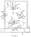
- Figure 1 is a top plan view, with portions cut-away, of a four station assembly apparatus 20 utilized in stacking and welding rotor laminations for dynamoelectric machines.
- a first work station 22 is provided for stacking the laminations to a desired height
- a second work station 24 is provided for measuring the height of the lamination stack to ensure that the proper number of laminations have been stacked at first station 22
- a third work station 26 is provided for skewing the laminations and then welding the laminations together
- a fourth work station 28 is provided for unloading the welded laminations.
- each work station 22 - 28 The specific equipment utilized at each work station 22 - 28 varies depending upon the task being performed. For example, at third work station 26, three welding heads 30A - C are utilized to weld the lamination stack. At fourth work station 28, a robotic arm 32 is provided to lift the welded lamination stack and place the stack on a conveyor 34. Stations 22-28 are positioned at locations along the periphery of a table 36, which table 36 is rotatable about a central axis as illustrated by the arrow X.
- Four work locations 38A - D are located at equally spaced positions around the periphery of rotatable table 32. Work locations 38A - D are positioned so that when any one work location is operatively aligned with a work station, the other work locations also are operatively aligned, respectively, with one of the other work stations.
- the present invention is not limited to use with any particular type of work station arrangement.
- the system illustrated in Figure 1 therefore is provided just to illustrate one type of environment in which the present invention is useful.
- the present invention may be utilized in many other types of work environments such as, for example, with the apparatus described in U.S. Patent No. 4,400,872, which is assigned to the present assignee.
- Figure 2 is a top plan view of first work location 38A of Fig. 1, which work location 38A is typical of each of the other work locations 38B - D.
- Work location 38A includes a base member 40 defining a planar surface for receiving and locating a first rotor lamination.
- Work location 38A further includes an elongated central mandrel 42 extending upwardly from base member 40 and perpendicular to the plane of base member 40.
- Central mandrel 42 is cylindrical shaped and has a longitudinally extending flat surface 44 extending along its length.
- a skew pin 46 also extends upwardly from base member 40.
- Skew pin 46 is attached to a skew pin angle setting arm 48 which is pivotally movable relative to central mandrel 42 to enable adjusting the angle of skew pin 48 relative to mandrel 42.
- a gear unit 50 controls pin 46 and arm 48, and is hereinafter described and illustrated in more detail.
- FIG 3 is a top plan view of a typical rotor lamination 52.
- Rotor lamination 52 is a generally planar disc shape member defining a central opening or hole 54 therethrough.
- Rotor lamination 52 importantly also includes a plurality of skew holes 56 therethrough. Skew holes 56 are located at angularly spaced positions radially outwardly from central hole 54.
- Central hole 54 of lamination 52 is adapted for cooperatively receiving the central mandrels 42 of each of the work stations 38A - D, and each of the skew pin holes 56 is adapted for receiving skew pin 46, as shown for example in phantom lines in Fig. 2.
- Figure 4 is a side elevational view of work location 38A, and shows the relative positions of central mandrel 42, skew pin 46 and skew pin angle setting arm 48.
- central, opening 54 of lamination 52 is aligned with central mandrel 42.
- Skew pin hole 54 formed in lamination 52 is aligned with the top of skew pin 46, and lamination 52 is then slid down central mandrel 42 and skew pin 46 onto base member 40 or on the previously loaded lamination. Laminations are loaded in this manner until the desired stack height is obtained.
- Gear unit 50 is illustrated in cross-section in Figure 4.
- Unit 50 includes a rotatable gear 58 disposed within a housing 60.
- Gear 58 controls movement of arm 48 and generally normally biases arm 48 so that its axis is substantially parallel to the axis of mandrel 42.
- a connecting arm 62 couples skew angle setting arm 48 and skew pin 46.
- Connecting arm 66 is coupled to a mandrel holding member 64 by a slider 66 disposed within a groove 68 formed in member 64.
- Setting arm 48 is mounted to gear 58 by a first hinge member 70 which allows arm 48 to rotate relative to housing 60.
- skew pin 46 is mounted by a second hinge member 72 to a fixture 74 so that skew pin 46 may rotate with arm 48.
- a stop pin 76 is illustrated as being mounted in an operative relationship with arm 48 and, as described hereinafter, is utilized to limit the movement of arm 48.
- a number of other elements such as bolts 78 and 80 utilized in mounting housing 60 and holding various components of unit 50 in place are illustrated. Importantly, the drawings and description of unit 50 are provided just for background purposes to describe one context in which the present tool can be utilized.
- Figure 5 is a rear view of work location 38A, showing skew pin 46 and skew pin angle setting arm 48 at one selected angular orientation relative to central mandrel 42.
- location 38A is disposed at third work station 26.
- an arm 82 at such station 26 contacts arm 48 and moves arm 48 to the angularly offset position as shown.
- skew pin 46 also rotates thereby skewing laminations (not shown in Fig. 5) stacked on mandrel 42. Once the laminations are so skewed, the welding operation is performed.
- a first geared plunger 84 and a second geared plunger 86 are disposed in channels 88 and 90, respectively.
- Such spring biasing results in gear 58 being normally biased to rotate counterclockwise.
- setting arm 48 and skew pin 46 also rotate.
- Stop pin 76 limits the amount of such rotation once setting arm 48 makes contact with such pin 76. Stop pin 76 is disposed so that rotation of setting arm 48 is stopped in the counterclockwise direction once the axis of setting arm 48 is substantially parallel to the axis of mandrel 42.
- an adjustable skew angle stop bolt 94 is threadedly engaged to a stop plate 96 mounted to housing 60 by bolts 98A-B.
- a threaded nut 100 assists in maintaining the selected location of stop bolt 94 relative to plate 96.
- stop bolt 94 limits the movement of second plunger 86, which in turn, limits the clockwise rotation of gear 58. Such a limit, of course, further limits the rotation of setting arm 48 and skew pin 46.
- the skew angle therefore may be adjusted by selecting the position of stop bolt 94 within channel 90. Specifically, robotic arm 82 rotates setting arm 48 until second plunger 86 contacts stop bolt 94. Once such contact is made, arm 82 maintains setting arm 48 in such position until completion of the welding operation, thereby fixing the laminations at the selected skew angle.
- FIG. 6 is an illustration representative of a stack of rotor laminations of a desired height.
- Skew pin 46 extends through a skew pin hole 56A of a first or bottommost rotor lamination 52A and through skew pin hole 56B of an uppermost or top rotor lamination 52B.
- the angular orientation of skew pin 46 illustrates the skew angle for the stack of laminations 52.
- Figure 7 illustrates a skew angle setting tool 102 embodying the present invention in one form thereof.
- tool 102 includes a base plate 104 and a sleeve 106 mounted thereon.
- Sleeve 106 defines a passage 108 therethrough having a central axis perpendicular to the planar top surface of base plate 104.
- An opening 108 formed in plate 104 is aligned and coaxial with sleeve passage 108.
- An adjustable plate 110 having a central opening 112 is mounted to sleeve 106 by passing sleeve 106 through plate central opening 112.
- a lock screw 114 threadedly engaged with adjustable plate 110 is engageable with sleeve 106 to maintain the position of adjustable plate 110 relative to sleeve 106.
- Graduations 116 are provided along a portion of the length of sleeve 106 to indicate the position of adjustable plate 110 relative to the planar top surface of base plate 104.
- adjustable plate 110 also has a plurality of skew pin alignment notches 118A-F formed therein along its outer circumference.
- a skew pin slot 120 is also provided in the adjustable plate.
- an operator In performing a work location set-up, an operator is provided with the present tool along with an indication as to which notch 118A-F skew pin 46 is to be aligned with for the particular rotor construction to be assembled, as well as the height selected for the particular rotor construction.
- the operator then aligns central mandrel 42 with opening 108 formed in base plate 104 and sleeve 106 and slides tool 102 over central mandrel 42.
- Proper alignment of notches 118A-F and slot 120 with skew angle setting arm 48 and skew pin 46, respectively, can be maintained by engaging a set screw or other means (not shown) on sleeve 106 with flat surface 44 of central mandrel 42.
- Skew pin 46 passes through skew pin slot 120 formed in adjustable plate 110 when tool 102 is installed, and skew pin angle setting arm 48 can then be aligned with and inserted into one notch 118 formed in adjustable plate 110 to set the skew angle such as by adjusting stop bolt 94 (not shown in Figure 8).
- skew pin angle setting arm 48 is shown in a first position in notch 118D, which positions skew pin 46 as shown in slot 120.
- Skew pin angle setting arm 48 is shown in phantom lines in a second position in notch 118A, and skew pin 46 is shown in phantom lines in corresponding position in slot 120.
- Figure 9 shows skew pin angle setting arm 48 in a third position in notch 118C of adjustable plate 110, illustrating another alternative skew pin orientation.
- Figures 10 and 11 illustrates a skew angle setting tool 122 embodying the present invention in another form thereof.
- tool 122 includes a base plate 124 having a column 126 mounted thereon.
- Column 126 defines a passage 128 therethrough having a central axis perpendicular to a planar top surface 130 of base plate 124.
- An opening 132 formed in base plate 124 is aligned and coaxial with column passage 128.
- a locating pin 134 is mounted on base plate 124 and extends downwardly therefrom.
- Locating pin 134 is insertable in a hole (not shown) provided at a work location as central mandrel 42 of the work location is inserted through opening 132 of base plate 124 for orienting base plate 124 in predetermined relation to central mandrel 42.
- Column 126 is formed of a plurality of stackable members, including a lower bushing member 136 adapted for mounting to top surface 130 of base plate 124, and a number of spacers 138, 140, 142 and 144 positionable on member 136.
- Each spacer 138 - 144 may be of a different known thickness and includes a central passage therethrough forming a segment of passage 128, and means for mounting to the adjoining spacer (not shown).
- column 126 can be assembled to any desired height corresponding to a particular rotor lamination stack height.
- the stackable members also include a skew angle setting member 146 mountable on spacers 138 - 144 for setting the skew angle for a rotor lamination stack of the desired height.
- Skew angle setting member 146 includes a plurality of elongated cylindrical arms 148, 150, 152, and 154 extending outwardly from column 126 for setting the skew angle.
- each arm 148-154 is offset with respect to central axis 156 of column 126 by a predetermined amount.
- tool 122 is positioned on a work location with a central mandrel located in passage 128 of column 126, and locating pin 134 inserted into a locating hole associated with the work location for aligning the tool with the work location, one of the arms 148 - 154 will be positioned so as to be engageable by skew pin angle setting arm 48 of the work location.
- skew angle setting member 146 is mountable on the uppermost spacer 144 in any of four different orientations 90° apart.
- arms 148 - 154 positions one edge or surface of the selected arm, as discussed above, at the proper location for setting skew pin 46 at a selected skew angle for a particular rotor lamination stack height.
- edge 156 of arm 154 is shown in engagement with skew pin angle setting arm 48 for setting one skew pin angle.
- skew angle setting member 146 could be mounted on column 126 with any of the other arms 148 - 154 positioned at the location of arm 154, and the different offsets of the respective arms would locate skew pin angle setting arm 48 at a different skew angle.
- different skew angles setting members having arms located at various offset values can be provided for setting the skew angle for rotor laminations for use in different diameter stator cases.
- Fig. 12 is a table showing the setting member arm offset values for setting skew angles of 15.5°, 18°, 20° and 22° for rotor lamination stack heights of 2 inches, 3 inches, 4 inches, and 5 inches, for a 3 inch diameter stator core.
- Fig. 13 is a table showing the offset values for skew angle setting member arms for setting skew angles of 15.5°, 18°, 20° and 22° for rotor lamination stack heights of 2 inches, 3 inches, 4 inches and 5 inches, for a 2.6 inch diameter stator core.
- the above-described embodiments of the present tool simplify the process of setting the skew pin angle by eliminating the need for an operator to make a mathematical calculation in station set up and the need for visual alignment of the skew pin with a protractor in setting the skew angle.
- An operator simply sets the tool to the desired stack height and then, once the tool is placed in proper position relative to the skew angel setting arm, disposes the arm in a selected plate notch or against an arm of the tool.
- Such a mechanical alignment of an angle setting arm into an adjustment plate notch or against an arm or other means reduces the amount of time required to set the skew pin angle and reduces the possibility for operator error and improves consistency in making skew pin angle settings.
Landscapes
- Engineering & Computer Science (AREA)
- Manufacturing & Machinery (AREA)
- Power Engineering (AREA)
- Manufacture Of Motors, Generators (AREA)
Applications Claiming Priority (2)
| Application Number | Priority Date | Filing Date | Title |
|---|---|---|---|
| US08/335,257 US5584119A (en) | 1994-11-07 | 1994-11-07 | Apparatus for setting skew angle |
| US335257 | 1994-11-07 |
Publications (3)
| Publication Number | Publication Date |
|---|---|
| EP0711021A2 true EP0711021A2 (de) | 1996-05-08 |
| EP0711021A3 EP0711021A3 (de) | 1998-02-25 |
| EP0711021B1 EP0711021B1 (de) | 2005-12-28 |
Family
ID=23310979
Family Applications (1)
| Application Number | Title | Priority Date | Filing Date |
|---|---|---|---|
| EP95307401A Expired - Lifetime EP0711021B1 (de) | 1994-11-07 | 1995-10-18 | Verfahren und Vorrichtung zum Einstellen der Schräge zwischen den Nuten |
Country Status (3)
| Country | Link |
|---|---|
| US (2) | US5584119A (de) |
| EP (1) | EP0711021B1 (de) |
| CN (1) | CN1322657C (de) |
Cited By (2)
| Publication number | Priority date | Publication date | Assignee | Title |
|---|---|---|---|---|
| RU2171532C1 (ru) * | 2000-12-15 | 2001-07-27 | ООО "КД-Электро" | Способ изготовления пакетов листов ротора электрической машины и приспособление для шихтовки и запрессовки пакета листов ротора электрической машины |
| WO2001080401A1 (en) * | 2000-04-15 | 2001-10-25 | European Electrical Laminations Limited | Rotor, rotor assembly, method and machine for manufacture of rotor elements |
Families Citing this family (12)
| Publication number | Priority date | Publication date | Assignee | Title |
|---|---|---|---|---|
| ITSV20040041A1 (it) * | 2004-11-29 | 2005-02-28 | Dema S R L | Procedimento per la formazione di un pacco di lamierini per la costruzione di armature di macchine elettriche o simili e dispositivo per l'attuazione di detto procedimento |
| DE102009006017A1 (de) * | 2009-01-23 | 2010-08-05 | Avantis Ltd. | Magnetrad |
| DE102009005956A1 (de) * | 2009-01-23 | 2010-07-29 | Avantis Ltd. | Magnetring |
| US8973251B2 (en) * | 2009-04-15 | 2015-03-10 | Toyota Jidosha Kabushiki Kaisha | Method for manufacturing stator |
| JP5791179B2 (ja) * | 2011-07-22 | 2015-10-07 | 日特エンジニアリング株式会社 | スキュー付ステータの製造装置 |
| CN105406659B (zh) * | 2015-12-10 | 2017-09-05 | 中船重工电机科技股份有限公司 | 内外双转子电机的装配工装及其装配方法 |
| CN106568369B (zh) * | 2016-10-21 | 2019-05-14 | 大连橡胶塑料机械有限公司 | 新型螺旋元件高度与相位角度同步测量装置 |
| US10644576B2 (en) * | 2017-12-30 | 2020-05-05 | Abb Schweiz Ag | Method for manufacturing an electrical machine |
| CN111682722B (zh) * | 2020-06-15 | 2021-10-15 | 常州金康精工机械股份有限公司 | 定子的扭斜槽装置 |
| EP3940931A1 (de) * | 2020-07-14 | 2022-01-19 | Siemens Aktiengesellschaft | Verfahren zur herstellung eines rotors einer asynchronmaschine |
| DE102020212358A1 (de) | 2020-09-30 | 2022-03-31 | Valeo Siemens Eautomotive Germany Gmbh | Verfahren zur Herstellung eines geschrägten Stators |
| CN113765312B (zh) * | 2021-09-28 | 2022-08-02 | 安徽威灵汽车部件有限公司 | 转子压装方法、转子、电动助力转向电机及车辆 |
Citations (1)
| Publication number | Priority date | Publication date | Assignee | Title |
|---|---|---|---|---|
| US4400872A (en) | 1981-08-13 | 1983-08-30 | General Electric Company | Method of and apparatus for skewing a stack of laminations |
Family Cites Families (5)
| Publication number | Priority date | Publication date | Assignee | Title |
|---|---|---|---|---|
| US3075106A (en) * | 1961-03-09 | 1963-01-22 | Gen Electric | Dynamoelectric machine |
| DE2907261A1 (de) * | 1979-02-24 | 1980-09-04 | Balzer & Droell Kg | Verfahren und vorrichtung zur herstellung von rotor- und statorblechpaketen fuer elektrische maschinen |
| US4400812A (en) * | 1981-06-15 | 1983-08-23 | Santa Barbara Research Center | Laser drive circuits |
| US4602427A (en) * | 1985-07-19 | 1986-07-29 | Artran Automation, Inc. | Skew setting mechanism for rotor assembly machine |
| DE3529050C1 (de) * | 1985-08-13 | 1986-04-30 | Siemens AG, 1000 Berlin und 8000 München | Paketierungsvorrichtung fuer Blechpakete,insbesondere fuer geschraenkte Rotor-Blechpakete |
-
1994
- 1994-11-07 US US08/335,257 patent/US5584119A/en not_active Expired - Fee Related
-
1995
- 1995-10-18 EP EP95307401A patent/EP0711021B1/de not_active Expired - Lifetime
- 1995-11-07 CN CNB951177060A patent/CN1322657C/zh not_active Expired - Fee Related
-
1996
- 1996-09-23 US US08/718,662 patent/US5722154A/en not_active Expired - Fee Related
Patent Citations (1)
| Publication number | Priority date | Publication date | Assignee | Title |
|---|---|---|---|---|
| US4400872A (en) | 1981-08-13 | 1983-08-30 | General Electric Company | Method of and apparatus for skewing a stack of laminations |
Cited By (3)
| Publication number | Priority date | Publication date | Assignee | Title |
|---|---|---|---|---|
| WO2001080401A1 (en) * | 2000-04-15 | 2001-10-25 | European Electrical Laminations Limited | Rotor, rotor assembly, method and machine for manufacture of rotor elements |
| US6952943B2 (en) | 2000-04-15 | 2005-10-11 | European Electrical Laminations Limited | Method and machine of manufacture of rotor elements |
| RU2171532C1 (ru) * | 2000-12-15 | 2001-07-27 | ООО "КД-Электро" | Способ изготовления пакетов листов ротора электрической машины и приспособление для шихтовки и запрессовки пакета листов ротора электрической машины |
Also Published As
| Publication number | Publication date |
|---|---|
| CN1322657C (zh) | 2007-06-20 |
| EP0711021B1 (de) | 2005-12-28 |
| CN1127950A (zh) | 1996-07-31 |
| US5722154A (en) | 1998-03-03 |
| EP0711021A3 (de) | 1998-02-25 |
| US5584119A (en) | 1996-12-17 |
Similar Documents
| Publication | Publication Date | Title |
|---|---|---|
| US5584119A (en) | Apparatus for setting skew angle | |
| US8061171B2 (en) | Automated manufacturing machine | |
| US5025999A (en) | Coil winding form apparatus | |
| US5087849A (en) | Laminated parts and a method for manufacture thereof | |
| US4619028A (en) | Apparatus for manufacture of laminated parts | |
| US4563824A (en) | Method and apparatus for disc position centering | |
| EP2985890A1 (de) | Vorrichtung und verfahren zum einsetzen eines magneten in eine magneteinsatzbohrung eines rotorkerns | |
| KR101889945B1 (ko) | 자기-기어드 모터 동심축 일치형 조립장치 | |
| WO2000067253A1 (en) | Method and apparatus for balancing a spindle in a hard disk drive | |
| US5551142A (en) | Stator lamination jig system | |
| CN113497531A (zh) | 导线位置修正方法及导线位置修正装置 | |
| US5500993A (en) | Method for manufacturing armatures | |
| CN213275926U (zh) | 磁铁磁通量检测装置 | |
| JP2006109691A (ja) | 電気機械のための固定子 | |
| KR20220090872A (ko) | 런아웃 측정을 이용한 모터축 정렬 시스템 및 모터축 정렬 방법 | |
| US4602427A (en) | Skew setting mechanism for rotor assembly machine | |
| CN217776144U (zh) | 一种转位机构 | |
| CN120940692B (zh) | 一种可以自动校准的多功能镗孔机 | |
| US3101910A (en) | Wire guiding heads for coil winding machines | |
| JP2919529B2 (ja) | 不釣合い修正方法および装置 | |
| KR100201929B1 (ko) | 모터 권선장치 및 방법 | |
| US5335412A (en) | Working device for forcing armature shaft | |
| WO1995031031A2 (en) | Method and apparatus for manufacturing armatures | |
| Kamiya et al. | An Automated Coil Winding Machine for the SSC Dipole Magnets | |
| CN115302270A (zh) | 一种定子内孔定位装置及方法 |
Legal Events
| Date | Code | Title | Description |
|---|---|---|---|
| PUAI | Public reference made under article 153(3) epc to a published international application that has entered the european phase |
Free format text: ORIGINAL CODE: 0009012 |
|
| AK | Designated contracting states |
Kind code of ref document: A2 Designated state(s): FR IT |
|
| PUAL | Search report despatched |
Free format text: ORIGINAL CODE: 0009013 |
|
| AK | Designated contracting states |
Kind code of ref document: A3 Designated state(s): FR IT |
|
| 17P | Request for examination filed |
Effective date: 19980825 |
|
| 17Q | First examination report despatched |
Effective date: 20000605 |
|
| GRAP | Despatch of communication of intention to grant a patent |
Free format text: ORIGINAL CODE: EPIDOSNIGR1 |
|
| GRAS | Grant fee paid |
Free format text: ORIGINAL CODE: EPIDOSNIGR3 |
|
| GRAA | (expected) grant |
Free format text: ORIGINAL CODE: 0009210 |
|
| AK | Designated contracting states |
Kind code of ref document: B1 Designated state(s): FR IT |
|
| PG25 | Lapsed in a contracting state [announced via postgrant information from national office to epo] |
Ref country code: IT Free format text: LAPSE BECAUSE OF FAILURE TO SUBMIT A TRANSLATION OF THE DESCRIPTION OR TO PAY THE FEE WITHIN THE PRESCRIBED TIME-LIMIT;WARNING: LAPSES OF ITALIAN PATENTS WITH EFFECTIVE DATE BEFORE 2007 MAY HAVE OCCURRED AT ANY TIME BEFORE 2007. THE CORRECT EFFECTIVE DATE MAY BE DIFFERENT FROM THE ONE RECORDED. Effective date: 20051228 |
|
| ET | Fr: translation filed | ||
| PLBE | No opposition filed within time limit |
Free format text: ORIGINAL CODE: 0009261 |
|
| STAA | Information on the status of an ep patent application or granted ep patent |
Free format text: STATUS: NO OPPOSITION FILED WITHIN TIME LIMIT |
|
| 26N | No opposition filed |
Effective date: 20060929 |
|
| PGFP | Annual fee paid to national office [announced via postgrant information from national office to epo] |
Ref country code: IT Payment date: 20071029 Year of fee payment: 13 |
|
| PGFP | Annual fee paid to national office [announced via postgrant information from national office to epo] |
Ref country code: FR Payment date: 20071017 Year of fee payment: 13 |
|
| REG | Reference to a national code |
Ref country code: FR Ref legal event code: ST Effective date: 20090630 |
|
| PG25 | Lapsed in a contracting state [announced via postgrant information from national office to epo] |
Ref country code: IT Free format text: LAPSE BECAUSE OF NON-PAYMENT OF DUE FEES Effective date: 20081018 |
|
| PG25 | Lapsed in a contracting state [announced via postgrant information from national office to epo] |
Ref country code: FR Free format text: LAPSE BECAUSE OF NON-PAYMENT OF DUE FEES Effective date: 20081031 |