EP0711023B1 - Induktionsmotor mit axialem Luftspalt - Google Patents
Induktionsmotor mit axialem Luftspalt Download PDFInfo
- Publication number
- EP0711023B1 EP0711023B1 EP95202924A EP95202924A EP0711023B1 EP 0711023 B1 EP0711023 B1 EP 0711023B1 EP 95202924 A EP95202924 A EP 95202924A EP 95202924 A EP95202924 A EP 95202924A EP 0711023 B1 EP0711023 B1 EP 0711023B1
- Authority
- EP
- European Patent Office
- Prior art keywords
- rotor
- highly permeable
- air gap
- induction motor
- permeable material
- Prior art date
- Legal status (The legal status is an assumption and is not a legal conclusion. Google has not performed a legal analysis and makes no representation as to the accuracy of the status listed.)
- Expired - Lifetime
Links
- 239000000463 material Substances 0.000 claims description 35
- XEEYBQQBJWHFJM-UHFFFAOYSA-N Iron Chemical compound [Fe] XEEYBQQBJWHFJM-UHFFFAOYSA-N 0.000 claims description 14
- 230000006698 induction Effects 0.000 claims description 13
- 229910052742 iron Inorganic materials 0.000 claims description 6
- 230000005291 magnetic effect Effects 0.000 claims description 6
- 229910052751 metal Inorganic materials 0.000 claims description 2
- 239000002184 metal Substances 0.000 claims description 2
- 239000011343 solid material Substances 0.000 claims 1
- 239000004020 conductor Substances 0.000 description 16
- 239000010949 copper Substances 0.000 description 8
- 229910052782 aluminium Inorganic materials 0.000 description 4
- XAGFODPZIPBFFR-UHFFFAOYSA-N aluminium Chemical compound [Al] XAGFODPZIPBFFR-UHFFFAOYSA-N 0.000 description 4
- 230000005294 ferromagnetic effect Effects 0.000 description 4
- 230000002093 peripheral effect Effects 0.000 description 4
- 239000000835 fiber Substances 0.000 description 3
- 238000004519 manufacturing process Methods 0.000 description 3
- 230000011218 segmentation Effects 0.000 description 3
- 238000004804 winding Methods 0.000 description 3
- RYGMFSIKBFXOCR-UHFFFAOYSA-N Copper Chemical compound [Cu] RYGMFSIKBFXOCR-UHFFFAOYSA-N 0.000 description 2
- 238000010276 construction Methods 0.000 description 2
- 229910052802 copper Inorganic materials 0.000 description 2
- 230000007547 defect Effects 0.000 description 2
- 239000007787 solid Substances 0.000 description 2
- 229910000737 Duralumin Inorganic materials 0.000 description 1
- 229910000976 Electrical steel Inorganic materials 0.000 description 1
- 229910000640 Fe alloy Inorganic materials 0.000 description 1
- 239000004411 aluminium Substances 0.000 description 1
- 230000008878 coupling Effects 0.000 description 1
- 238000010168 coupling process Methods 0.000 description 1
- 238000005859 coupling reaction Methods 0.000 description 1
- 230000002950 deficient Effects 0.000 description 1
- 230000000694 effects Effects 0.000 description 1
- 230000002349 favourable effect Effects 0.000 description 1
- 230000004907 flux Effects 0.000 description 1
- 239000012634 fragment Substances 0.000 description 1
- 239000000696 magnetic material Substances 0.000 description 1
- 238000000034 method Methods 0.000 description 1
- 229910000679 solder Inorganic materials 0.000 description 1
Images


Classifications
-
- H—ELECTRICITY
- H02—GENERATION; CONVERSION OR DISTRIBUTION OF ELECTRIC POWER
- H02K—DYNAMO-ELECTRIC MACHINES
- H02K17/00—Asynchronous induction motors; Asynchronous induction generators
- H02K17/02—Asynchronous induction motors
- H02K17/16—Asynchronous induction motors having rotors with internally short-circuited windings, e.g. cage rotors
- H02K17/168—Asynchronous induction motors having rotors with internally short-circuited windings, e.g. cage rotors having single-cage rotors
Definitions
- the invention relates to an induction motor with a pole Stand and with a rotor arranged in a radial air gap opposite the poles, which is made of electrically good conductive and magnetically good conductive material is, the electrically highly conductive material on the side facing the stator of the rotor and has a smaller specific weight than the magnetically good conductive highly permeable material, and wherein the outer radius of the annular or disc-shaped, magnetically highly conductive, highly permeable material is smaller than the outer radius of the ring or disc-shaped, electrically highly conductive material.
- Such an induction motor is from the article I.E.E.E Transactions on Magnetics, Vol. 24, No. 1, January 1988, N.Y. USA, pages 635-638.
- Another induction motor is e.g. made known by EP 0 487 141 A2.
- This known motor is part of a blower unit for generating gas flows, especially for vacuum cleaners, and has a compressor impeller, which at the same time is electromagnetically effective and together with electromagnetically active parts of the Motor stand generates the torque of the compressor impeller.
- the electromagnetic effective part of the compressor impeller is one in the radial plane opposite the stator arranged conductive plate that limits the radial air gap on the rotor side.
- the electric conductive plate of the rotor is e.g. a base plate of the compressor impeller and exists e.g. made of aluminium.
- This electrically conductive base plate of the rotor is on their from Air gap remote side surface with a plate of highly permeable, i.e. magnetic good conductive material, e.g. made of solid iron, deposited.
- DE-PS 843 719 is an induction motor with one opposite the front of the known poles of its stator arranged disc-shaped short-circuit rotor known become.
- the short-circuit rotor is e.g. from an iron disc that is at least on the stator facing side is covered with a Cu jacket.
- This Cu jacket can be made of a sprayed-on Cu layer or from two to different sides of the Fe disk arranged Cu discs exist.
- the Fe disc on both Pages with copper washers their flanged edges are soldered together.
- These Cu disks can too can be connected by a number of Cu rivets. The induced short circuit currents then go through the through the solder joint and further inside through the rivet.
- the e.g. made of iron or an iron alloy highly permeable (magnetically good conductive) rotor layer on the one hand a much greater specific weight than e.g. aluminum layer with good electrical conductivity.
- it is maximum permissible mechanical tension of the highly permeable rotor layer is not so much greater that in comparison to the electrically highly conductive layer at least the same large maximum permissible peripheral speed results. It follows that the critical Material stress can be found in the highly permeable rotor layer.
- a hysteresis motor has become known from DE-A-17 63 113.
- the runner has e.g. support body made of duralumin, the from the rotor axis in the radial direction to the circumference in accordance with a Tapered body of the same strength.
- the ones described at the beginning Generic types, however, a rotor that is adjacent to the stator on its Side must not have a magnetically good conductive material. Located on this site rather, it is only an electrically highly conductive material.
- the invention has for its object a simple manufacturing To create induction motor of the type mentioned, in which despite the high Speeds no strength problems with the different used here Runner materials occur.
- This object is achieved according to the invention in that the ring or disc-shaped highly permeable material on the side of the electrical facing away from the air gap good conductive material is placed.
- the radius of the magnetically conductive Ring is also less than that of the electrically conductive carrier, but not from mechanical, but for electromagnetic reasons.
- the torque is in the magnetically conductive ferromagnetic ring due to the remanence of the magnetic material generated in the design according to the invention, however, in the electrically conductive Layer of the rotor due to electrical currents.
- the runner runs synchronously with the Rotating field around, in the design according to the invention, the rotor runs slower than that Rotating field.
- the magnetically conductive ring itself lies on the air gap.
- the highly permeable Material is made of wound sheet metal or wire.
- This design has the advantage that the flow in the rotor yoke does not go through Segment boundaries is interrupted, however, the available volume is at this construction is only partially filled with highly permeable material. With this design the yoke can support itself, so that no surrounding material as in a segment construction is needed.
- the Wire winding has the advantage that each fiber, in the event of overuse, when applied a high energy, must be destroyed individually, so that this from a defective rotor Design runs less hazard potential.
- Another embodiment of the invention provides that the highly permeable material axially layered sheets is constructed. Similar to a segmentation, the Check the mass of the fragments that occur if the material fails. In contrast the highly permeable part can support itself for segmentation.
- the motor described is preferably used as a drive motor in one Vacuum cleaner.
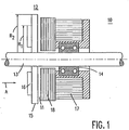
- the rotor 12 is constructed from two materials, namely from an electrically highly conductive material 15 (aluminum) and from a magnetically highly conductive material 16 (iron).
- the magnetically highly conductive material 16 has a greater specific weight than the electrically highly conductive material 15, is ring-shaped and is placed on the rotor 12 in such a way that only a layer of electrically highly conductive material lies on the side facing the stator 10.
- the outer radius R 1 of the magnetically highly conductive material is smaller than the outer radius R 2 of the electrically highly conductive material.
- the stand 10 has an iron sleeve formed by winding an electrical steel strip 17, into which grooves (not shown) for receiving a winding 18 are introduced.
- the disc formed from material 15 with good electrical conductivity Eddy currents are generated while the magnetically highly conductive, highly permeable material 16 serves to transmit the magnetic flux.
- FIG. 2 shows a top view of the rotor from direction A according to FIG. 1.
- Fig. 3 shows a cross section of the rotor, in which the highly permeable, from axial layered sheets of existing material 16 '' 'on the highly conductive material 15 is put on.
- Fig. 4 shows a vacuum cleaner with an induction motor.
Landscapes
- Engineering & Computer Science (AREA)
- Power Engineering (AREA)
- Induction Machinery (AREA)
- Connection Of Motors, Electrical Generators, Mechanical Devices, And The Like (AREA)
- Iron Core Of Rotating Electric Machines (AREA)
Description

Claims (5)
- Induktionsmotor mit einem Pole aufweisenden Ständer (10) und mit einem in einem Axialluftspalt (11) gegenüber den Polen angeordneten Läufer (12), der aus elektrisch gut leitfähigem und aus magnetisch gut leitfähigem Werkstoff (15, 16) gefertigt ist, wobei der elektrisch gut leitfähige Werkstoff (15) auf der dem Ständer (10) zugewandten Seite des Läufers (12) liegt und ein kleineres spezifisches Gewicht als der magnetisch gut leitfähige hochpermeable Werkstoff (16) aufweist, wobei der Außenradius (R1) des ring- oder scheibenförmig ausgebildeten, magnetisch gut leitfähigen hochpermeablen Werkstoffes (16) kleiner ist als der Außenradius (R2) des ring- oder scheibenförmig ausgebildeten, elektrisch gut leitfähigen Werkstoffes (15), dadurch gekennzeichnet, daß der ring- oder scheibenförmige hochpermeable Werkstoff (16) auf die dem Luftspalt abgewandte Seite des elektrisch gut leitfähigen Werkstoffes (15) aufgesetzt ist.
- Induktionsmotor nach Anspruch 1, dadurch gekennzeichnet, daß der hochpermeable Werkstoff (16) aus massivem Werkstoff, z.B. Eisen, hergestellt ist.
- Induktionsmotor nach Anspruch 1, dadurch gekennzeichnet, daß der hochpermeable Werkstoff aus gewickeltem Blech (16') oder aus gewickeltem Draht (16") aufgebaut ist.
- Induktionsmotor nach Anspruch 1, dadurch gekennzeichnet, daß der hochpermeable Werkstoff aus axial geschichteten Blechen (16"') aufgebaut ist.
- Staubsauger mit einem Induktionsmotor nach Anspruch 1.
Priority Applications (1)
| Application Number | Priority Date | Filing Date | Title |
|---|---|---|---|
| EP00121121A EP1098426B1 (de) | 1994-11-07 | 1995-10-30 | Induktionsmotor mit axialem Luftspalt |
Applications Claiming Priority (2)
| Application Number | Priority Date | Filing Date | Title |
|---|---|---|---|
| DE4439690A DE4439690A1 (de) | 1994-11-07 | 1994-11-07 | Induktionsmotor |
| DE4439690 | 1994-11-07 |
Related Child Applications (1)
| Application Number | Title | Priority Date | Filing Date |
|---|---|---|---|
| EP00121121.8 Division-Into | 2000-09-28 |
Publications (3)
| Publication Number | Publication Date |
|---|---|
| EP0711023A2 EP0711023A2 (de) | 1996-05-08 |
| EP0711023A3 EP0711023A3 (de) | 1996-10-30 |
| EP0711023B1 true EP0711023B1 (de) | 2001-04-25 |
Family
ID=6532659
Family Applications (2)
| Application Number | Title | Priority Date | Filing Date |
|---|---|---|---|
| EP95202924A Expired - Lifetime EP0711023B1 (de) | 1994-11-07 | 1995-10-30 | Induktionsmotor mit axialem Luftspalt |
| EP00121121A Expired - Lifetime EP1098426B1 (de) | 1994-11-07 | 1995-10-30 | Induktionsmotor mit axialem Luftspalt |
Family Applications After (1)
| Application Number | Title | Priority Date | Filing Date |
|---|---|---|---|
| EP00121121A Expired - Lifetime EP1098426B1 (de) | 1994-11-07 | 1995-10-30 | Induktionsmotor mit axialem Luftspalt |
Country Status (4)
| Country | Link |
|---|---|
| US (1) | US5608281A (de) |
| EP (2) | EP0711023B1 (de) |
| JP (1) | JPH08214513A (de) |
| DE (3) | DE4439690A1 (de) |
Cited By (4)
| Publication number | Priority date | Publication date | Assignee | Title |
|---|---|---|---|---|
| US7900315B2 (en) | 2005-10-07 | 2011-03-08 | Cube Investments Limited | Integrated central vacuum cleaner suction device and control |
| US8096014B2 (en) | 2005-10-07 | 2012-01-17 | Cube Investments Limited | Central vacuum cleaner control, unit and system with contaminant sensor |
| US8516653B2 (en) | 2004-09-17 | 2013-08-27 | Cube Investments Limited | Cleaner handle and cleaner handle housing sections |
| US8732895B2 (en) | 2005-10-07 | 2014-05-27 | Cube Investments Limited | Central vacuum cleaner multiple vacuum source control |
Families Citing this family (9)
| Publication number | Priority date | Publication date | Assignee | Title |
|---|---|---|---|---|
| GB0001121D0 (en) * | 2000-01-19 | 2000-03-08 | Rolls Royce Plc | Rotor disc |
| DE10047592A1 (de) * | 2000-09-26 | 2002-04-25 | Siemens Ag | Lüftervorrichtung mit elektromagnetischer Kupplung |
| US7382072B2 (en) * | 2003-05-22 | 2008-06-03 | Erfurt & Company | Generator |
| US6856113B1 (en) | 2004-05-12 | 2005-02-15 | Cube Investments Limited | Central vacuum cleaning system motor control circuit mounting post, mounting configuration, and mounting methods |
| CN101865209B (zh) * | 2004-11-12 | 2012-07-18 | 谢夫勒两合公司 | 旋转连接装置 |
| CA2562804C (en) | 2005-10-07 | 2014-12-09 | Cube Investments Limited | Vacuum cleaner cross-control |
| US8598761B2 (en) * | 2007-05-03 | 2013-12-03 | In Motion Technologies Pty., Ltd. | Rotor magnet positioning device |
| EP3035076B1 (de) * | 2014-12-17 | 2020-08-19 | Leica Geosystems AG | Vermessungsgerät mit Positioniereinrichtung |
| US11616410B2 (en) | 2020-01-10 | 2023-03-28 | Samsung Electronics Co., Ltd. | Cleaner |
Family Cites Families (12)
| Publication number | Priority date | Publication date | Assignee | Title |
|---|---|---|---|---|
| NL81396C (de) * | 1949-05-24 | |||
| US2880335A (en) * | 1956-03-30 | 1959-03-31 | Gen Electric | Induction motor |
| US2956169A (en) * | 1956-12-07 | 1960-10-11 | Rutledge F King | Ion pulse generation |
| US3008062A (en) * | 1957-12-12 | 1961-11-07 | Tkm Electric Corp | Dynamoelectric machine |
| US3128401A (en) * | 1960-08-01 | 1964-04-07 | Ford Motor Co | Element for eddy current devices |
| DE1763113C3 (de) * | 1968-04-05 | 1976-01-02 | Licentia Patent-Verwaltungs-Gmbh, 6000 Frankfurt | Wechsel- oder Drehstrommotor dessen Ständerwicklung einen Jochringkern umschließt |
| GB1508428A (en) * | 1974-07-25 | 1978-04-26 | Sealed Motor Constr Co Ltd | Axial gap electric motors |
| DD120576A1 (de) * | 1975-05-20 | 1976-06-12 | ||
| US4132910A (en) * | 1976-11-11 | 1979-01-02 | Muanyagipari Kutato Intezet | Linearly moving or rotated flat armature for motor and pulling magnets |
| IT8383524A0 (it) * | 1983-12-27 | 1983-12-27 | Seima Italiana Spa | Barrette per catadiottri. |
| US5288216A (en) * | 1990-11-23 | 1994-02-22 | U.S. Philips Corporation | Fan unit for generating gas streams |
| DE4037229A1 (de) * | 1990-11-23 | 1992-05-27 | Philips Patentverwaltung | Geblaeseaggregat zum erzeugen von gasstroemen |
-
1994
- 1994-11-07 DE DE4439690A patent/DE4439690A1/de not_active Withdrawn
-
1995
- 1995-10-30 DE DE59510552T patent/DE59510552D1/de not_active Expired - Fee Related
- 1995-10-30 DE DE59509216T patent/DE59509216D1/de not_active Expired - Fee Related
- 1995-10-30 EP EP95202924A patent/EP0711023B1/de not_active Expired - Lifetime
- 1995-10-30 EP EP00121121A patent/EP1098426B1/de not_active Expired - Lifetime
- 1995-11-06 JP JP7287114A patent/JPH08214513A/ja active Pending
- 1995-11-06 US US08/554,123 patent/US5608281A/en not_active Expired - Fee Related
Cited By (4)
| Publication number | Priority date | Publication date | Assignee | Title |
|---|---|---|---|---|
| US8516653B2 (en) | 2004-09-17 | 2013-08-27 | Cube Investments Limited | Cleaner handle and cleaner handle housing sections |
| US7900315B2 (en) | 2005-10-07 | 2011-03-08 | Cube Investments Limited | Integrated central vacuum cleaner suction device and control |
| US8096014B2 (en) | 2005-10-07 | 2012-01-17 | Cube Investments Limited | Central vacuum cleaner control, unit and system with contaminant sensor |
| US8732895B2 (en) | 2005-10-07 | 2014-05-27 | Cube Investments Limited | Central vacuum cleaner multiple vacuum source control |
Also Published As
| Publication number | Publication date |
|---|---|
| DE4439690A1 (de) | 1996-05-09 |
| DE59510552D1 (de) | 2003-03-13 |
| EP1098426A1 (de) | 2001-05-09 |
| EP1098426B1 (de) | 2003-02-05 |
| EP0711023A2 (de) | 1996-05-08 |
| US5608281A (en) | 1997-03-04 |
| JPH08214513A (ja) | 1996-08-20 |
| DE59509216D1 (de) | 2001-05-31 |
| EP0711023A3 (de) | 1996-10-30 |
Similar Documents
| Publication | Publication Date | Title |
|---|---|---|
| EP0711023B1 (de) | Induktionsmotor mit axialem Luftspalt | |
| DE69218470T2 (de) | Stator und Rotor aufweisende, scheibenförmige Maschine mit hohem Wirkungsgrad und kleiner Reaktanz | |
| DE69524380T2 (de) | Elektromotor mit axialem fluss und offenem stator | |
| DE60123726T2 (de) | Hybrider synchronmotor mit ringförmiger wicklung | |
| DE843719C (de) | Induktionsmotor | |
| EP0908630A1 (de) | Kleinlüftereinheit, insbesondere zur Verwendung als Leiterplattenlüfter | |
| EP0954087A1 (de) | Elektrodynamisches Getriebe und Kreiselpumpe mit einem derartigen Getriebe | |
| DE1760382A1 (de) | Trommelwaschmaschine | |
| DE3323297C2 (de) | ||
| DE102012022152A1 (de) | Elektrische Maschine und Rotor für eine elektrische Maschine | |
| DE69606685T2 (de) | Induktionsmotor mit axialem Luftspalt | |
| DE3542372C2 (de) | ||
| WO2021148069A1 (de) | Rotor und axialflussmaschine | |
| EP0274150A2 (de) | Einphasensynchronmotor mit einem zweipoligen, dauermagnetischen Rotor und mit einem Wirbelstrom-Zwischenläufer | |
| DE4419780A1 (de) | Ringförmiger Stator für elektrodynamische Drehmaschine | |
| DE102015013662A1 (de) | Elektromotor | |
| DE102022111689A1 (de) | Rotorkerndesign | |
| DE69507890T2 (de) | Magnetlager | |
| DE69411780T2 (de) | Elektrische maschine mit einem als geschlossener Magnetkreis wirkenden sowie die rotierende Welle aufnehmenden Gehäuse | |
| DE10055080A1 (de) | Elektrische Linearmaschine | |
| DE10245015B4 (de) | Elektromotor und Umwälzpumpe | |
| DE9114582U1 (de) | Elektrische Maschine | |
| DE102004025226A1 (de) | Elektromotor, insbesondere Spindelmotor | |
| DE3502284A1 (de) | Kollektorloser gleichstrommotor | |
| DE1538715C (de) | Elektromaschine mit kugelförmigem Luftspalt |
Legal Events
| Date | Code | Title | Description |
|---|---|---|---|
| PUAI | Public reference made under article 153(3) epc to a published international application that has entered the european phase |
Free format text: ORIGINAL CODE: 0009012 |
|
| AK | Designated contracting states |
Kind code of ref document: A2 Designated state(s): DE FR GB IT SE |
|
| PUAL | Search report despatched |
Free format text: ORIGINAL CODE: 0009013 |
|
| AK | Designated contracting states |
Kind code of ref document: A3 Designated state(s): DE FR GB IT SE |
|
| 17P | Request for examination filed |
Effective date: 19970502 |
|
| 17Q | First examination report despatched |
Effective date: 19980205 |
|
| RAP3 | Party data changed (applicant data changed or rights of an application transferred) |
Owner name: KONINKLIJKE PHILIPS ELECTRONICS N.V. Owner name: PHILIPS PATENTVERWALTUNG GMBH |
|
| RAP3 | Party data changed (applicant data changed or rights of an application transferred) |
Owner name: KONINKLIJKE PHILIPS ELECTRONICS N.V. Owner name: PHILIPS CORPORATE INTELLECTUAL PROPERTY GMBH |
|
| GRAG | Despatch of communication of intention to grant |
Free format text: ORIGINAL CODE: EPIDOS AGRA |
|
| GRAG | Despatch of communication of intention to grant |
Free format text: ORIGINAL CODE: EPIDOS AGRA |
|
| GRAH | Despatch of communication of intention to grant a patent |
Free format text: ORIGINAL CODE: EPIDOS IGRA |
|
| GRAH | Despatch of communication of intention to grant a patent |
Free format text: ORIGINAL CODE: EPIDOS IGRA |
|
| GRAA | (expected) grant |
Free format text: ORIGINAL CODE: 0009210 |
|
| AK | Designated contracting states |
Kind code of ref document: B1 Designated state(s): DE FR GB IT SE |
|
| REF | Corresponds to: |
Ref document number: 59509216 Country of ref document: DE Date of ref document: 20010531 |
|
| GBT | Gb: translation of ep patent filed (gb section 77(6)(a)/1977) |
Effective date: 20010511 |
|
| ITF | It: translation for a ep patent filed | ||
| ET | Fr: translation filed | ||
| PGFP | Annual fee paid to national office [announced via postgrant information from national office to epo] |
Ref country code: SE Payment date: 20011026 Year of fee payment: 7 |
|
| REG | Reference to a national code |
Ref country code: GB Ref legal event code: IF02 |
|
| PLBE | No opposition filed within time limit |
Free format text: ORIGINAL CODE: 0009261 |
|
| STAA | Information on the status of an ep patent application or granted ep patent |
Free format text: STATUS: NO OPPOSITION FILED WITHIN TIME LIMIT |
|
| 26N | No opposition filed | ||
| PG25 | Lapsed in a contracting state [announced via postgrant information from national office to epo] |
Ref country code: SE Free format text: LAPSE BECAUSE OF NON-PAYMENT OF DUE FEES Effective date: 20021031 |
|
| EUG | Se: european patent has lapsed | ||
| PGFP | Annual fee paid to national office [announced via postgrant information from national office to epo] |
Ref country code: GB Payment date: 20041028 Year of fee payment: 10 |
|
| PGFP | Annual fee paid to national office [announced via postgrant information from national office to epo] |
Ref country code: DE Payment date: 20041214 Year of fee payment: 10 |
|
| PGFP | Annual fee paid to national office [announced via postgrant information from national office to epo] |
Ref country code: FR Payment date: 20051027 Year of fee payment: 11 |
|
| PG25 | Lapsed in a contracting state [announced via postgrant information from national office to epo] |
Ref country code: IT Free format text: LAPSE BECAUSE OF NON-PAYMENT OF DUE FEES;WARNING: LAPSES OF ITALIAN PATENTS WITH EFFECTIVE DATE BEFORE 2007 MAY HAVE OCCURRED AT ANY TIME BEFORE 2007. THE CORRECT EFFECTIVE DATE MAY BE DIFFERENT FROM THE ONE RECORDED. Effective date: 20051030 Ref country code: GB Free format text: LAPSE BECAUSE OF NON-PAYMENT OF DUE FEES Effective date: 20051030 |
|
| PG25 | Lapsed in a contracting state [announced via postgrant information from national office to epo] |
Ref country code: DE Free format text: LAPSE BECAUSE OF NON-PAYMENT OF DUE FEES Effective date: 20060503 |
|
| GBPC | Gb: european patent ceased through non-payment of renewal fee |
Effective date: 20051030 |
|
| REG | Reference to a national code |
Ref country code: FR Ref legal event code: ST Effective date: 20070629 |
|
| PG25 | Lapsed in a contracting state [announced via postgrant information from national office to epo] |
Ref country code: FR Free format text: LAPSE BECAUSE OF NON-PAYMENT OF DUE FEES Effective date: 20061031 |