EP0711214B1 - Kokille zum stranggiessen - Google Patents
Kokille zum stranggiessen Download PDFInfo
- Publication number
- EP0711214B1 EP0711214B1 EP94924799A EP94924799A EP0711214B1 EP 0711214 B1 EP0711214 B1 EP 0711214B1 EP 94924799 A EP94924799 A EP 94924799A EP 94924799 A EP94924799 A EP 94924799A EP 0711214 B1 EP0711214 B1 EP 0711214B1
- Authority
- EP
- European Patent Office
- Prior art keywords
- ingot mould
- tube
- ingot
- mold
- mould body
- Prior art date
- Legal status (The legal status is an assumption and is not a legal conclusion. Google has not performed a legal analysis and makes no representation as to the accuracy of the status listed.)
- Expired - Lifetime
Links
- 238000009749 continuous casting Methods 0.000 title claims abstract description 9
- 238000007789 sealing Methods 0.000 claims abstract description 27
- 239000002184 metal Substances 0.000 claims abstract description 20
- 229910052751 metal Inorganic materials 0.000 claims abstract description 20
- 230000010358 mechanical oscillation Effects 0.000 claims abstract description 18
- 238000001816 cooling Methods 0.000 claims abstract description 11
- 238000006073 displacement reaction Methods 0.000 claims abstract description 5
- 229910052802 copper Inorganic materials 0.000 claims description 21
- 239000010949 copper Substances 0.000 claims description 21
- RYGMFSIKBFXOCR-UHFFFAOYSA-N Copper Chemical compound [Cu] RYGMFSIKBFXOCR-UHFFFAOYSA-N 0.000 claims description 20
- 230000033001 locomotion Effects 0.000 claims description 17
- 230000003534 oscillatory effect Effects 0.000 claims description 12
- 238000005266 casting Methods 0.000 claims description 9
- 230000002706 hydrostatic effect Effects 0.000 claims description 6
- 239000000110 cooling liquid Substances 0.000 claims 5
- 239000012528 membrane Substances 0.000 description 26
- 239000002826 coolant Substances 0.000 description 15
- 230000002093 peripheral effect Effects 0.000 description 10
- 230000010355 oscillation Effects 0.000 description 9
- 229910000831 Steel Inorganic materials 0.000 description 6
- 239000010959 steel Substances 0.000 description 6
- 208000031968 Cadaver Diseases 0.000 description 5
- 206010039509 Scab Diseases 0.000 description 4
- 238000009434 installation Methods 0.000 description 4
- 238000005192 partition Methods 0.000 description 3
- 230000005540 biological transmission Effects 0.000 description 2
- 230000004927 fusion Effects 0.000 description 2
- 238000005461 lubrication Methods 0.000 description 2
- 238000012423 maintenance Methods 0.000 description 2
- 238000000034 method Methods 0.000 description 2
- 238000003756 stirring Methods 0.000 description 2
- 229920002449 FKM Polymers 0.000 description 1
- 238000010276 construction Methods 0.000 description 1
- 150000001879 copper Chemical class 0.000 description 1
- 238000005520 cutting process Methods 0.000 description 1
- 230000001627 detrimental effect Effects 0.000 description 1
- 229920001971 elastomer Polymers 0.000 description 1
- 239000000806 elastomer Substances 0.000 description 1
- 230000002349 favourable effect Effects 0.000 description 1
- 239000000835 fiber Substances 0.000 description 1
- 230000009931 harmful effect Effects 0.000 description 1
- 239000007788 liquid Substances 0.000 description 1
- 239000000463 material Substances 0.000 description 1
- 230000007935 neutral effect Effects 0.000 description 1
- 238000000926 separation method Methods 0.000 description 1
- 230000035939 shock Effects 0.000 description 1
- 238000007711 solidification Methods 0.000 description 1
- 230000008023 solidification Effects 0.000 description 1
- 230000003313 weakening effect Effects 0.000 description 1
Images


Classifications
-
- B—PERFORMING OPERATIONS; TRANSPORTING
- B22—CASTING; POWDER METALLURGY
- B22D—CASTING OF METALS; CASTING OF OTHER SUBSTANCES BY THE SAME PROCESSES OR DEVICES
- B22D11/00—Continuous casting of metals, i.e. casting in indefinite lengths
- B22D11/04—Continuous casting of metals, i.e. casting in indefinite lengths into open-ended moulds
-
- B—PERFORMING OPERATIONS; TRANSPORTING
- B22—CASTING; POWDER METALLURGY
- B22D—CASTING OF METALS; CASTING OF OTHER SUBSTANCES BY THE SAME PROCESSES OR DEVICES
- B22D11/00—Continuous casting of metals, i.e. casting in indefinite lengths
- B22D11/04—Continuous casting of metals, i.e. casting in indefinite lengths into open-ended moulds
- B22D11/053—Means for oscillating the moulds
Definitions
- the present invention relates to a mold for a continuous casting installation according to the preamble of claim 1, which is based on EP-A-0 432 128.
- Such a continuous casting ingot mold comprises a mold tube defining an axial flow channel for a molten metal and a mold body, surrounding the mold tube over at least part of its length.
- This mold body contains a cooling circuit of the mold body.
- the mold tube is vigorously cooled by the cooling circuit integrated in the mold body.
- the molten metal solidifies on contact with the internal wall of the ingot mold tube to form a peripheral crust. It should be noted that an attachment or bonding of this solidified peripheral crust to the internal wall of the ingot mold tube would produce a tearing of the peripheral crust. In order to avoid this risk, it is known to subject the mold to an oscillatory movement along the casting axis.
- an oscillation table which is provided with a device generating mechanical oscillations. This oscillation table then transmits to the mold an oscillatory movement oriented along the casting axis.
- an ingot mold for casting steel billets has - with its ingot mold tube, its ingot mold body, its cooling circuit filled with a liquid cooling and possibly an electromagnetic inductor to stir the molten metal - easily a mass of the order of 3 tonnes.
- This mass must be able to confer oscillations of an amplitude of a few millimeters with a frequency of the order of 5 Hz and more. It is therefore necessary to use a device generating oscillations very powerful mechanical; all the more since this device must not only overcome the inertia of the mold itself, but also the inertia of the structure of the support structure, as well as the friction forces between the internal wall of the mold tube and the metal in fusion.
- the high powers involved in producing the oscillations of the mold have the harmful effects of noisy shocks and vibrations detrimental to the mechanical strength of certain elements of the mold.
- the purpose of the present invention is to provide an ingot mold which opposes the device generating mechanical oscillations a substantially reduced mass of inertia.
- the mass in oscillatory movement is substantially reduced to the mass of the mold tube.
- the mass of the ingot mold tube represents little more than 5% of the total mass of the ingot mold.
- the most massive elements of the mold, namely the body of the mold with its cooling circuit filled with a coolant and, if necessary, the electromagnetic inductor are stationary on a support frame and must not be put in motion by the device generating mechanical oscillations. This considerably reduces the powers involved to produce a relative oscillatory movement between the internal wall of the ingot mold tube and the peripheral crust of the cast product. This results in a weakening of the forces and vibrations that the continuous casting installation must undergo; hence an increase in the lifespan of some of its elements.
- the mold body and the inductor which no longer participate in the oscillatory movement, are no longer subjected to dynamic stresses, which also has a favorable influence on their lifespan. It will also be appreciated the absence of an oscillating support structure for the mold significantly reduces the investment and maintenance costs.
- the mold body is preferably designed so as to define at its upper and lower end a passage opening for the mold tube.
- the sealing elements are then arranged in these two passage openings, so as to delimit axially in the mold body a sealed annular chamber which can be pressurized by the coolant. It is then advantageous to dimension the cross section of the upper passage opening larger than the cross section of the lower passage opening. This difference in section in fact results in a hydrostatic force on the ingot mold tube which is oriented in the opposite direction to the flow of the molten metal. This hydrostatic force makes it possible to compensate for the weight of the ingot mold tube, as well as the friction that the molten metal exerts on the internal wall of the ingot mold tube. It will therefore be appreciated that this solution makes it possible to further reduce the powers necessary to produce said oscillatory movement.
- the mold body includes an inner guide jacket which surrounds the mold tube and forms therewith a first annular space defining a first passage section for a coolant.
- An outer jacket surrounds said inner guide jacket and forms therewith a second annular space, defining a second passage section for the coolant which is substantially larger than said first passage section.
- the inner guide liner is rigidly fixed to the outer wall of the mold body and forms a sheath in which the mold tube can slide axially.
- This inner guide jacket which has a relatively low weight, can however also be part of the mold tube. In this case it is set in oscillation together with the mold tube.
- the ingot mold tube advantageously comprises an inner tube, which defines the flow channel for the molten metal and which is most often a copper tube, and a cage which surrounds this copper tube.
- This cage is rigidly and tightly fixed at its upper end to the copper tube and has at its lower end a guide opening in which the copper tube is tightly guided, so that it can expand axially downwards.
- the inner guide jacket for the coolant is then supported by this cage surrounding the copper tube.
- Said sealing elements include lower sealing elements which are connected between the lower end of the cage and the mold body and upper sealing elements which are connected between the upper end of the cage and the body of the mold. ingot mold.
- the sealing elements may for example include an axial bellows compensator which is connected between a flange secured to the mold tube and a flange secured to the mold body.
- the sealing elements comprise at least one elastically deformable membrane. The latter is located in a plane transverse to the casting axis. It is a particularly simple execution which ensures a perfect seal, does not require any maintenance and allows to realize a very compact construction of the mold.
- An advantageous solution consists in providing a lever as a means of mechanical connection between the device generating mechanical oscillations and the ingot mold tube. This then comprises an intermediate articulation by means of which it is supported by the mold body, a first lever arm connected to the device generating mechanical oscillations and a second lever arm which supports the mold tube.
- This embodiment makes it possible to install the device generating mechanical oscillations laterally next to the mold, where it does not interfere and where it can be protected against splashes of molten metal. Since the mold tube is supported by the lever arm, itself supported by the mold body, it is not necessary to provide other means for supporting the mold tube. In particular, said sealing elements must not fulfill the function of supporting the mold tube in the mold body.
- the ingot mold tube is suspended in the lever arm preferably by means of two pins housed in a forked arm with two branches.
- a particularly compact embodiment of the ingot mold is obtained when said intermediate articulation of the lever arm, the two pins and the second lever arm are located inside said sealed chamber.
- the second lever arm must then cross the outer jacket of the mold body in a leaktight manner.
- the seal between the second lever arm and the outer jacket of the mold body is advantageously achieved by means of a bellows compensator, which is preferably installed inside said sealed chamber.
- a bellows compensator which is preferably installed inside said sealed chamber.
- Leaf springs preferably connected between the mold body and the mold tube guide the latter axially and prevent the sealing elements from transmitting excessive transverse forces.
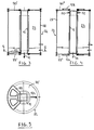
- Figures 1 and 2 show an ingot mold 10 which can be used for example for the continuous casting of metal steel billets. It comprises an ingot mold tube 12 having an internal wall 14 and an external wall 16. The internal wall 14 defines a flow channel 18 for the molten steel. Reference 20 marks the central axis of this channel, which can be straight or curved. Most often the ingot mold tube is a thick-walled copper tube. The internal section of this tube defines the section of the cast product. In Figure 2 a square section is represented; this section could however also be rectangular, circular or have any other shape. The arrow marked with the reference 21 indicates the direction of flow of the molten steel through the ingot mold tube 12.
- the ingot mold tube 12 must be cooled vigorously in order to cause solidification of the molten steel in contact with its internal wall 14. To this end, it is surrounded, normally over its entire height, by an ingot mold body 22 which contains, in a sealed chamber 23, a cooling circuit for the external wall 16 of the mold tube 12.
- the cooling circuit shown in Figure 1 is known per se.
- An inner guide sleeve 24 surrounds the mold tube 12 over almost its entire height and forms around the external wall 16 of the mold tube 12 a first annular space 26, with a very narrow annular passage section.
- An outer jacket 28 of the mold body 22 surrounds the inner guide jacket 24 and forms with the latter a second annular space 30, which surrounds the first annular space 26 and defines a substantially larger annular passage section.
- a coolant supply circuit is represented schematically by the arrow 32. The coolant enters through an annular supply chamber 34, located on the side of the lower end of the mold 10, in the first annular space 26 It crosses the latter at high speed and against the current relative to the direction of casting 21, to exit into the second annular space 30.
- the inner guide sleeve 24 is provided with an external flange 38 which is tightly fixed to an internal counter-flange 40 of the external sleeve 28. From this so the inner guide liner 24 is rigidly supported by the liner outside 28 of the mold body 22, and the annular supply chamber 34 is at the same time sealed in separation from said second annular space 30.
- the mold body 22 is provided at its lower end with a peripheral base 42 which defines a passage opening 43 for the mold tube 12. With this lower peripheral base 42 the mold body is supported on a fixed support frame, represented schematically by two beams identified by the reference 44.
- a mechanical oscillation generating device 46 is supported on the support frame next to the mold body 22 (the support of the mechanical oscillation generating device 46 on the supporting frame 44 is not shown in Figure 1). It is for example a hydraulic piston provided with a hydraulic circuit known per se, which is capable of communicating to a piston rod 48 a reciprocating movement of an amplitude of a few millimeters and a frequency of a few hertz. However, it could also be a rotary motor provided with an eccentric which produces mechanical oscillations. The piston rod 48 would in this case be replaced by a connecting rod.
- the hydraulic piston however has the advantage of allowing easy and flexible adjustment of the amplitude, frequency and shape of the mechanical oscillations produced.
- the mold tube 12 is provided at its upper end with two pins 50 and 52. These are arranged on two opposite sides of the outer wall 16 of the mold tube 12, so that their axes are aligned and perpendicular to the axis 20 of the ingot mold tube 12. With the aid of these pins 50 and 52 the mold tube is supported by a forked arm 56.
- the two pins 50, 52 are more precisely articulated in a first branch 58, respectively a second branch 60 of the forked arm 56, so as to define a pivot axis 61 of the mold tube 12 which is perpendicular to the direction of casting.
- the two pins 50, 52 are located in said second annular space 30 defined between the inner guide jacket 24 on one side and the outer jacket 28 on the other side.
- the forked arm 56 is part of a lever 54 mounted in the mold body 22.
- This lever 54 comprises in the second annular space 30 a tilting axis 63 which is parallel to the pivoting axis 61 of the mold tube 12.
- This tilting axis 63 is advantageously embodied by two pivots 64 and 66 which are mounted symmetrically on the mold body 22.
- Each of the branches 58, 60 of the forked arm 56 is then provided with a cylindrical housing 68, 70 for a of the two pivots 64, 66. It will be noted that each of the pivots 64, 66 can be mounted from the outside of the mold body 22, in order to allow easy assembly and disassembly of the lever 54.
- the outer jacket 28 of the ingot mold body 22 is provided with two support blocks 72, 74 in which the pivots 64 and 66 are housed in a through bore.
- Each pivot 64, 66 is provided with a fixing flange 76, 78 which is fixed by means of screws (not shown) on the support block 72, 74.
- a joint between the flange 76, 78 and the support block 72, 74 ensures, preferably together with one or more O-rings in the passage bore of the support block 72, 74, the sealing of this assembly.
- the lever 54 On the side opposite to the forked arm 56, the lever 54 comprises a second lever arm 80 which passes in leaktight manner through the outer jacket 28 of the mold body 22.
- This sealed passage is preferably carried out using a bellows compensator 82, which is tightly connected with its first end to the outer jacket 28 of the mold body 22 and with its second end to a shoulder of the second lever arm 80.
- the second lever arm 80 is connected by means of a cylindrical articulation 84, with an axis parallel to the pivot axis 63 of the lever 54, to the piston rod 48.
- the two pins 50, 52, the forked arm 56, the pivot axis 63, most of the second lever arm 80 and the bellows compensator 82 are integrated in the second annular space 30.
- This embodiment not only makes it possible to have a compact size of the mold 10, but also ensures effective protection of these elements. It will also be noted that all of these elements are immersed in the coolant, which ensures a certain lubrication of the joints.
- the back and forth movement of the piston rod 48 is transmitted by the lever 54 to the mold tube 12.
- the latter is mounted in the mold body 22 and connected to the latter so as to be able to follow the oscillatory movement of the lever 54. It follows that the mold tube 12 is subjected to a forced oscillatory movement relative to the mold body 22 which remains stationary.
- the moving mass therefore corresponds to the mass of the ingot mold tube 12 which is generally at least twenty times smaller than the total mass of the ingot mold, which comprises, outside the ingot mold tube 12, the ingot mold body 22 filled with 'a coolant and possibly an electromagnetic inductor 86.
- the latter which is used for stirring molten steel, is integrated in a manner known per se into said second annular space 30 of the mold body 22, in which it is supported by the outer jacket 28 of the mold body 22.
- This inductor 86 is therefore also immobile relative to the mold tube which is subject to the oscillatory movement.
- the outer jacket 28 is connected, at these two axial ends, in leaktight manner to the external wall 16 of the mold body 22 by means of sealing elements which allow an axial displacement of the mold tube 12 relative to the mold body. 22.
- sealing elements preferably comprise a lower membrane 88, delimiting said sealed chamber 23 of the ingot mold body 22 axially at its lower end, and an upper membrane 90, delimiting the latter axially at its upper end.
- These are annular membranes contained in a plane transverse to the casting axis and elastically deformable in a direction perpendicular to their surface. Multi-sheet metal membranes may for example be suitable for this use.
- the lower annular membrane 88 is connected on one side with its outer peripheral edge to the peripheral base 42 of the mold body 22 and on the other side with its inner edge to a lower flange 92.
- This the latter is made integral with the lower end of the mold tube 12 by means of keys 94, 96, which are housed in a groove 98 of the mold tube 12.
- the keys 94 and 96, as well as the inner edge of the lower membrane 88 are fixed by clamping between the flange 92 and a counter-flange 100, which is fixed by screws to the flange 92. Seals provide sealing for this assembly.
- the outer edge of the membrane 88 is fixed by clamping between the peripheral base 42 and a counter-flange 110.
- Seals provide sealing between the membrane 88 and the peripheral base 42, respectively the counter-flange 110.
- the mounting of the upper membrane 90 is carried out in a similar manner.
- a counter flange 114 fixes the outer edge of the upper membrane 90 to an upper ring 116 secured to the outer jacket 28 of the mold body 22.
- This upper ring 116 defines an upper passage opening 117 for the mold tube 12.
- a counter flange 118 fixes the inner edge of the upper membrane 90 to an upper flange 120 of the mold tube 12.
- the upper flange 120 is made integral with the upper end of the mold tube 12 in the same way as the lower flange 90
- the two pins 50 and 52 are moreover advantageously supported by said upper flange 120 (cf. FIG. 1).
- FIG. 5 shows by way of example such a leaf spring 122, which has three branches spaced 45 ° apart.
- This element 122 can easily be deformed perpendicular to the plane of the drawing and at the same time has a high resistance to a tensile force. It is preferably mounted on the side of the lower end of the ingot mold tube 12, since the upper end is already rigidly supported in the forked arm 56 of the lever arm 54. In addition, this element 122 is mounted so as to be tensile stress.
- the arrow 124 shows by way of example the horizontal component of the tensile force which the cast product extracted from the ingot mold tube 12 exerts on the lower end of the latter. This force, which is far from negligible, is transmitted by the element 122 of the mold tube 12 to the mold body 22; the membrane 88 'is not involved in this transmission.
- the axis of the ingot mold defines an arc of a circle
- the pivot axis 61 of the ingot mold tube 12 in the forked arm 56, the pivot axis 63 of the lever 54 and the axis of the cylindrical joint 84 are in this case arranged so that they are cut every three by a straight line also passing through said center of curvature. It follows that the ingot mold tube oscillates along a trajectory which substantially follows the curvature of the product cast at the level of the ingot mold tube.
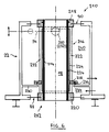
- FIG. 6 shows a particularly interesting variant of an ingot mold 210 according to the invention.
- An ingot mold tube 212 includes a copper tube 214 which defines the axial flow channel 18 for the molten metal.
- the copper tube 214 is surrounded by a cage 216. This comprises stiffening elements 222 connecting an upper flange 218 and a lower flange 220.
- the upper flange 218 is rigidly fixed to the upper end of the copper tube 214.
- the lower flange 220 surrounds the copper tube 214 in a leaktight manner, but is not rigidly fixed to the latter.
- a seal for example a VITON ® seal or an O-ring resistant to high temperatures, seals between the lower flange 220 and the copper tube 214.
- the cage 216 supports a guide jacket 224 which defines a narrow annular passage space 226 for the coolant around the copper tube 214.
- This guide jacket 224 is provided with a collar 228 which cooperates with an annular partition wall 230 of the mold body 22, to delimit in the mold 210 an annular supply chamber 234 of the annular space 226.
- the collar 228 and the partition wall 230 are connected together by a sealing element 236 which necessarily allows their relative displacement along the casting axis.
- the sealing element 236 comprises a ring which is fixed in leaktight manner to the partition wall 230 and which defines a labyrinth seal in an annular cavity of the collar 228. This labyrinth seal could, if necessary, be replaced by one or more O-rings.
- the copper tube 214, the cage 216 and the jacket for guiding the coolant 224 define, in the embodiment according to FIG. 6, a fairly rigid assembly, which is movable as a unit axially with respect to the mold body 22. This the assembly is supported by a lever arm 254 (represented in FIG. 6 by its axis) using the two pins 250, 252 which form part of the upper flange 218.
- the coolant enters the annular supply chamber 234, passes at high speed through the narrow annular space 226 where it undergoes a significant pressure drop, and comes out of the ingot mold after passing through the annular space 240, which can house, for example, an electromagnetic stirrer (not shown). Since the pressure in the annular supply chamber 234 is higher than the pressure in the annular chamber 240, the hydrostatic pressure which is exerted on the collar 228 contributes to supporting the assembly of copper tube 214, cage 216 and jacket coolant guidance 224.
Landscapes
- Engineering & Computer Science (AREA)
- Mechanical Engineering (AREA)
- Continuous Casting (AREA)
- Confectionery (AREA)
- Agricultural Chemicals And Associated Chemicals (AREA)
- Organic Low-Molecular-Weight Compounds And Preparation Thereof (AREA)
- Measuring Volume Flow (AREA)
Claims (16)
- Kokille einer Stranggußanlage, umfassend:ein Kokille-Rohr (12), das eine innere Wand (14) und eine äußere Wand (16) hat, wobei die innere Wand (14) einen axialen Ausflußkanal (18) für ein schmelzflüssiges Metall definiert;einen Kokille-Körper (22), der die äußere Wand (16) des Kokille-Rohrs (12) über mindestens einen Teil seiner Länge so umgibt, daß er damit eine dichte Kammer (23) definiert, die einen Kühlkreis zur Kühlung des Kokille-Rohrs (12) enthält; undeine Vorrichtung (46) zur Erzeugung von mechanischen Schwingungen,dadurch gekennzeichnet,daß das Kokille-Rohr (12) bezüglich des Kokille-Körpers (22) axial verschiebbar ist;daß der Kokille-Körper (22) mittels Dichtungselementen (88, 90), die eine axiale Verschiebung des Kokille-Rohrs (12) bezüglich des Kokille-Körpers (22) ermöglichen, während sie zugleich die Dichtheit der dichten Kammer (23) sicherstellen, mit dem Kokille-Rohr (12) verbunden ist; unddaß die Vorrichtung (46) zur Erzeugung von mechanischen Schwingungen mit dem Kokille-Rohr (12) so verbunden ist, daß sie eine axiale Schwingbewegung bezüglich des Kokille-Körpers (22) auf das Kokille-Rohr (12) übertragen kann.
- Kokille gemäß Anspruch 1, dadurch gekennzeichnet,daß der Kokille-Körper (22) eine obere Durchgangsöffnung (117) und eine untere Durchgangsöffnung (43) für das Kokille-Rohr (12) umfaßt,daß die Dichtungselemente (88, 90) in diesen zwei Durchgangsöffnungen (43, 117) so angeordnet sind, daß sie in dem Kokille-Körper (22) um das Kokille-Rohr (12) herum eine dichte ringförmige Kammer (23) begrenzen, die durch eine Kühlflüssigkeit unter Druck gesetzt werden kann, unddaß der Querschnitt der oberen Durchgangsöffnung (117) größer ist als der Querschnitt der unteren Durchgangsöffnung (43), so daß sich daraus eine auf das Kokille-Rohr (12) wirkende hydrostatische Kraft ergibt, die entgegengesetzt zu der Ausflußrichtung des schmelzflüssigen Metalls gerichtet ist.
- Kokille gemäß Anspruch 1 oder 2, dadurch gekennzeichnet, daß der Kokille-Körper (22) ein inneres Führungsrohr (24) umfaßt, das das Kokille-Rohr (12) umgibt und damit einen ersten ringförmigen Zwischenraum (26) bildet, der einen ersten Durchgangsquerschnitt für eine Kühlflüssigkeit definiert, und ein äußeres Mantelrohr (28) umfaßt, das das innere Führungsrohr (24) umgibt und damit einen zweiten ringförmigen Zwischenraum (30) bildet, der einen zweiten Durchgangsquerschnitt für die Kühlflüssigkeit bildet, der wesentlich größer als der erste Durchgangsquerschnitt ist.
- Kokille gemäß Anspruch 3, dadurch gekennzeichnet, daß das innere Führungsrohr (24) an dem Kokille-Körper (22) starr befestigt ist.
- Kokille gemäß Anspruch 3, dadurch gekennzeichnet, daß das innere Führungsrohr (224) ein Bestandteil des Kokille-Rohrs (212) ist.
- Kokille gemäß Anspruch 5, dadurch gekennzeichnet,daß das Kokille-Rohr (212) ein Kupferrohr (214) umfaßt, das den axialen Ausflußkanal (18) für das schmelzflüssige Metall definiert, und einen Käfig (216) umfaßt, der sich längs des Kupferrohrs (214) erstreckt, und der an seinem oberen Ende an dem Kupferrohr (214) auf starre und dichte Weise befestigt ist,daß dieser Käfig (216) an seinem unteren Ende eine Führungsöffnung aufweist, in der das Kupferrohr (214) auf dichte Weise so geführt wird, daß es sich axial nach unten ausdehnen kann, unddaß ein Führungsrohr (224) für die Kühlflüssigkeit von diesem Käfig (216) getragen wird.
- Kokille gemäß Anspruch 6, dadurch gekennzeichnet, daß die Dichtungselemente (88, 90) untere Dichtungselemente (88) umfassen, die zwischen dem unteren Ende des Käfigs (216) und dem Kokille-Körper (22) angeschlossen sind, und obere Dichtungselemente (90) umfassen, die zwischen dem oberen Ende des Käfigs (216) und dem Kokille-Körper (22) angeschlossen sind.
- Kokille gemäß Anspruch 6 oder 7, dadurch gekennzeichnet,daß der Käfig (216) mit einem Bundring (228) versehen ist,daß der Kokille-Körper (22) mit einer ringförmigen Trennwand (230) versehen ist,daß der Bundring (238) und die ringförmige Trennwand (230) in der Kokille (210) eine ringförmige Versorgungskammer (234) für eine Kühlflüssigkeit begrenzen, unddaß der Bundring (228) und die ringförmige Trennwand (230) durch ein Dichtungselement (236) miteinander verbunden sind, das ihre relative Verschiebung gemäß der Gießachse zuläßt.
- Kokille gemäß irgendeinem der Ansprüche 1 bis 8, dadurch gekennzeichnet, daß die Dichtungselemente mindestens eine elastisch verformbare Membran (88, 90) umfassen.
- Kokille gemäß Anspruch 9, dadurch gekennzeichnet, daß die Membran (88, 90) eine metallische Membran mit mehreren Folien ist.
- Kokille gemäß irgendeinem der Ansprüche 1 bis 10, gekennzeichnet durch einen Hebel (54), der mit einem Zwischengelenk (63) versehen ist, mittels dem er von dem Kokille-Körper (22) getragen wird, wobei der Hebel (54) einen ersten Hebelarm (56) umfaßt, der an seinem oberen Ende das Kokille-Rohr (12) trägt, und einen zweiten Hebelarm (80) umfaßt, der mit der Vorrichtung (46) zur Erzeugung von mechanischen Schwingungen verbunden ist.
- Kokille gemäß Anspruch 11, dadurch gekennzeichnet,daß das Kokille-Rohr (12) an seinem oberen Ende mit zwei Drehzapfen (50, 52) versehen ist; unddaß der zweite Hebelarm (56) ein gabelförmiger Arm mit zwei Zweigen (58, 60) ist, wobei jeder der Drehzapfen (50, 52) von einem dieser Zweige (58, 60) getragen wird.
- Kokille gemäß den Ansprüchen 3, 11 und 12, dadurch gekennzeichnet,daß das Zwischengelenk (63) des Hebelarms, die zwei Drehzapfen (50, 52), und der erste Hebelarm (56) innerhalb der dichten ringförmigen Kammer (23) gelegen sind, unddaß der zweite Hebelarm (80) durch das äußere Mantelrohr (28) des Kokille-Körpers (22) hindurchgeführt ist, und mittels eines Balgkompensators (82) auf dichte Weise mit diesem Mantelrohr verbunden ist.
- Kokille gemäß irgendeinem der Ansprüche 1 bis 13, dadurch gekennzeichnet, daß die dichte Kammer (23) einen elektromagnetischen Induktor (86) enthält, der von dem Kokille-Körper (22) getragen wird.
- Kokille gemäß irgendeinem der Ansprüche 1 bis 14, dadurch gekennzeichnet, daß die Vorrichtung (46) zur Erzeugung von mechanischen Schwingungen ein hydraulischer Kolben ist.
- Kokille gemäß irgendeinem der Ansprüche 1 bis 15, gekennzeichnet durch Blattfedern (122), die zwischen dem Kokille-Rohr (12) und dem Kokille-Körper (22) angeschlossen sind.
Applications Claiming Priority (3)
| Application Number | Priority Date | Filing Date | Title |
|---|---|---|---|
| LU88389A LU88389A1 (fr) | 1993-07-30 | 1993-07-30 | Lingotière de coulée continue |
| LU88389 | 1993-07-30 | ||
| PCT/EP1994/002442 WO1995003904A1 (fr) | 1993-07-30 | 1994-07-23 | Lingotiere de coulee continue |
Publications (2)
| Publication Number | Publication Date |
|---|---|
| EP0711214A1 EP0711214A1 (de) | 1996-05-15 |
| EP0711214B1 true EP0711214B1 (de) | 1997-03-19 |
Family
ID=19731430
Family Applications (1)
| Application Number | Title | Priority Date | Filing Date |
|---|---|---|---|
| EP94924799A Expired - Lifetime EP0711214B1 (de) | 1993-07-30 | 1994-07-23 | Kokille zum stranggiessen |
Country Status (16)
| Country | Link |
|---|---|
| US (1) | US5676194A (de) |
| EP (1) | EP0711214B1 (de) |
| JP (1) | JPH09500832A (de) |
| KR (1) | KR100286239B1 (de) |
| CN (1) | CN1042404C (de) |
| AT (1) | ATE150347T1 (de) |
| AU (1) | AU685836B2 (de) |
| BR (1) | BR9407336A (de) |
| CA (1) | CA2168354C (de) |
| CZ (1) | CZ284129B6 (de) |
| DE (1) | DE69402205T2 (de) |
| ES (1) | ES2100734T3 (de) |
| LU (1) | LU88389A1 (de) |
| PL (1) | PL178762B1 (de) |
| RO (1) | RO119933B1 (de) |
| WO (1) | WO1995003904A1 (de) |
Families Citing this family (15)
| Publication number | Priority date | Publication date | Assignee | Title |
|---|---|---|---|---|
| AT404442B (de) * | 1994-12-21 | 1998-11-25 | Voest Alpine Ind Anlagen | Stranggiesskokille |
| JP4156044B2 (ja) * | 1994-12-22 | 2008-09-24 | エスティーマイクロエレクトロニクス,インコーポレイテッド | 集積回路におけるランディングパッド構成体の製造方法 |
| DE19541164B4 (de) * | 1995-11-04 | 2005-02-17 | Sms Demag Ag | Oszillationseinrichtung für eine Stranggießkokille |
| LU88689A1 (de) * | 1995-12-22 | 1997-06-22 | Wurth Paul Sa | Stranggiesskokille |
| LU88701A1 (de) * | 1996-01-18 | 1997-07-18 | Wurth Paul Sa | Stranggiesskokille und Abdichtelement fuer Stranggiesskokille |
| ES2146437T3 (es) * | 1996-04-30 | 2000-08-01 | Danieli Off Mecc | Metodo para obtener vibraciones transversales en las paredes del cristalizador de una lingotera, mediante pulsacion del liquido refrigerante. |
| LU90071B1 (de) * | 1997-05-30 | 1998-12-01 | Wurth Paul Sa | Stranggiessvorrichtung |
| LU90222B1 (de) | 1998-03-11 | 1999-09-13 | Wurth Paul | Hubantrieb fuer den Einsatz in der Eisen- und Stahlindustrie |
| LU90666B1 (en) * | 2000-10-31 | 2002-05-02 | Wurth Paul Sa | Continous casting mould with oscillation device |
| LU91086B1 (en) * | 2004-06-25 | 2005-12-27 | Sms Demag Ag | Continous casting mould wit oscillation device. |
| CN1310721C (zh) * | 2005-04-11 | 2007-04-18 | 姜虹 | 连铸机轻型结晶器 |
| ITMI20112292A1 (it) * | 2011-12-16 | 2013-06-17 | Arvedi Steel Engineering S P A | Dispositivo di supporto ed oscillazione per lingottiera in impianti di colata continua |
| DE102012224161A1 (de) * | 2012-12-21 | 2014-06-26 | Siemens Vai Metals Technologies Gmbh | Temperaturfühler für eine Kokille in einer Stranggießmaschine |
| FR3026967B1 (fr) | 2014-10-10 | 2016-10-28 | Fives Fcb | Broyeur par compression de lit de matieres |
| CN115009528B (zh) * | 2022-07-07 | 2024-06-28 | 天津斑斓航空科技有限公司 | 一种主动倾转机翼的气压保护装置、飞行器及其方法 |
Family Cites Families (6)
| Publication number | Priority date | Publication date | Assignee | Title |
|---|---|---|---|---|
| US3565158A (en) * | 1968-11-04 | 1971-02-23 | Joseph J Ciochetto | Continuous-casting mold |
| US4483385A (en) * | 1981-11-05 | 1984-11-20 | Amb Technology, Inc. | System for oscillating mold tube in continuous steel casting machine |
| DE3207149C1 (de) * | 1982-02-27 | 1983-07-07 | Mannesmann AG, 4000 Düsseldorf | Stranggiesskokille fuer fluessige Metalle |
| WO1985004125A1 (en) * | 1984-03-19 | 1985-09-26 | Amb Technology, Inc. | Method and apparatus for the continuous casting of metal |
| AT394326B (de) * | 1989-12-04 | 1992-03-10 | Voest Alpine Ind Anlagen | Stranggiesskokille |
| DE4032333C2 (de) * | 1990-10-09 | 1994-03-17 | Mannesmann Ag | Traglager für kraftübertragende, oszillierende Hebel |
-
1993
- 1993-07-30 LU LU88389A patent/LU88389A1/fr unknown
-
1994
- 1994-07-23 PL PL94312745A patent/PL178762B1/pl unknown
- 1994-07-23 CZ CZ96264A patent/CZ284129B6/cs not_active IP Right Cessation
- 1994-07-23 ES ES94924799T patent/ES2100734T3/es not_active Expired - Lifetime
- 1994-07-23 DE DE69402205T patent/DE69402205T2/de not_active Expired - Lifetime
- 1994-07-23 BR BR9407336A patent/BR9407336A/pt not_active IP Right Cessation
- 1994-07-23 JP JP7505548A patent/JPH09500832A/ja active Pending
- 1994-07-23 AU AU74955/94A patent/AU685836B2/en not_active Ceased
- 1994-07-23 KR KR1019960700461A patent/KR100286239B1/ko not_active Expired - Fee Related
- 1994-07-23 US US08/583,030 patent/US5676194A/en not_active Expired - Lifetime
- 1994-07-23 CN CN94192938A patent/CN1042404C/zh not_active Expired - Lifetime
- 1994-07-23 AT AT94924799T patent/ATE150347T1/de active
- 1994-07-23 RO RO96-00165A patent/RO119933B1/ro unknown
- 1994-07-23 EP EP94924799A patent/EP0711214B1/de not_active Expired - Lifetime
- 1994-07-23 CA CA002168354A patent/CA2168354C/fr not_active Expired - Lifetime
- 1994-07-23 WO PCT/EP1994/002442 patent/WO1995003904A1/fr not_active Ceased
Also Published As
| Publication number | Publication date |
|---|---|
| AU685836B2 (en) | 1998-01-29 |
| CN1127998A (zh) | 1996-07-31 |
| ES2100734T3 (es) | 1997-06-16 |
| CA2168354C (fr) | 2004-09-14 |
| BR9407336A (pt) | 1996-06-18 |
| KR100286239B1 (ko) | 2001-06-01 |
| AU7495594A (en) | 1995-02-28 |
| PL312745A1 (en) | 1996-05-13 |
| PL178762B1 (pl) | 2000-06-30 |
| CA2168354A1 (fr) | 1995-02-09 |
| US5676194A (en) | 1997-10-14 |
| ATE150347T1 (de) | 1997-04-15 |
| CZ284129B6 (cs) | 1998-08-12 |
| LU88389A1 (fr) | 1995-02-01 |
| DE69402205T2 (de) | 1997-08-28 |
| WO1995003904A1 (fr) | 1995-02-09 |
| KR960703691A (ko) | 1996-08-31 |
| RO119933B1 (ro) | 2005-06-30 |
| CZ26496A3 (en) | 1996-05-15 |
| CN1042404C (zh) | 1999-03-10 |
| DE69402205D1 (de) | 1997-04-24 |
| EP0711214A1 (de) | 1996-05-15 |
| JPH09500832A (ja) | 1997-01-28 |
Similar Documents
| Publication | Publication Date | Title |
|---|---|---|
| EP0711214A1 (de) | Kokille zum stranggiessen | |
| WO1995005910A1 (fr) | Lingotiere de coulee continue | |
| EP0178967B1 (de) | Vibrierende Giessform zum Stranggiessen von Metallen | |
| FR2957829A1 (fr) | Rouleau brasseur pour machine de coulee continu de brames | |
| FR2483316A1 (fr) | Porte-outils, pour des outils destines notamment a la production de mousses de matieres plastiques | |
| EP0063072A1 (de) | Ausstattung einer Durchlaufgiessformanlage für Metalle | |
| KR20010013196A (ko) | 연속 주조 장비 | |
| EP0236237B1 (de) | Stranggussanlage für Metall | |
| BE1001428A6 (fr) | Dispositif de refroidissement d'un metal pendant la coulee. | |
| FR2571284A1 (fr) | Tiroir pivotant pour la busette de coulee de recipients metallurgiques | |
| EP0082744B1 (de) | Stranggiessanlage für Metall, insbesondere Mehrfach-Stranggiessanlage | |
| FR2535987A1 (fr) | Procede de formage d'un ou plusieurs bulbes, par deformation plastique en expansion de la paroi d'un troncon de tube | |
| FR2655282A1 (fr) | Dispositif de raccordement d'un tube de coulee a la busette de coulee d'un recipient contenant du metal en fusion. | |
| EP0176452B1 (de) | Vorrichtung zum Tragen und zur verstellbaren Orientierung von verschiedenen Elementen bezüglich einer Referenzebene | |
| EP2186632A1 (de) | Mounting system for sliding punches in a tablet press | |
| EP2379459B1 (de) | Verfahren zur beschichtung eines laserkomponents und dazu gehörende vorrichtung | |
| BE1004076A7 (fr) | Procede et dispositif pour supporter un produit metallique coule en continu. | |
| EP0484720B1 (de) | Vorrichtung zum Einblasen von vorerhitzter Luft in einem Schachtofen und Verfahren zum Herstellen konvexer Teile von Kugelgelenken für Düsenstöcke | |
| BE1011088A3 (fr) | Rouleau deflecteur de tole immerge dans un bain de metal fondu. | |
| FR2535632A1 (fr) | Dispositif de support et d'oscillation d'une lingotiere de coulee continue | |
| BE1005165A3 (fr) | Procede et dispositif pour la coulee continue d'un metal en fusion. | |
| BE1008567A6 (fr) | Structure de joint d'etancheite pour un recipient metallurgique. | |
| BE1013748A3 (fr) | Dispositif pour la coulee continue directe de l'acier. | |
| FR2681269A1 (fr) | Dispositif d'articulation pour le basculement d'une enceinte, notamment une poche de coulee de metal liquide. | |
| EP0399873A1 (de) | Einstellbarer Träger für ein Gas-Laser-Rohr und Laserapparat, ausgestattet mit einem solchen Träger |
Legal Events
| Date | Code | Title | Description |
|---|---|---|---|
| PUAI | Public reference made under article 153(3) epc to a published international application that has entered the european phase |
Free format text: ORIGINAL CODE: 0009012 |
|
| 17P | Request for examination filed |
Effective date: 19951211 |
|
| AK | Designated contracting states |
Kind code of ref document: A1 Designated state(s): AT BE CH DE ES FR GB IT LI NL PT |
|
| GRAG | Despatch of communication of intention to grant |
Free format text: ORIGINAL CODE: EPIDOS AGRA |
|
| 17Q | First examination report despatched |
Effective date: 19960613 |
|
| GRAH | Despatch of communication of intention to grant a patent |
Free format text: ORIGINAL CODE: EPIDOS IGRA |
|
| GRAH | Despatch of communication of intention to grant a patent |
Free format text: ORIGINAL CODE: EPIDOS IGRA |
|
| GRAA | (expected) grant |
Free format text: ORIGINAL CODE: 0009210 |
|
| AK | Designated contracting states |
Kind code of ref document: B1 Designated state(s): AT BE CH DE ES FR GB IT LI NL PT |
|
| REF | Corresponds to: |
Ref document number: 150347 Country of ref document: AT Date of ref document: 19970415 Kind code of ref document: T |
|
| REG | Reference to a national code |
Ref country code: CH Ref legal event code: EP |
|
| REF | Corresponds to: |
Ref document number: 69402205 Country of ref document: DE Date of ref document: 19970424 |
|
| REG | Reference to a national code |
Ref country code: CH Ref legal event code: NV Representative=s name: TROESCH SCHEIDEGGER WERNER AG |
|
| GBT | Gb: translation of ep patent filed (gb section 77(6)(a)/1977) |
Effective date: 19970424 |
|
| ITF | It: translation for a ep patent filed | ||
| REG | Reference to a national code |
Ref country code: ES Ref legal event code: FG2A Ref document number: 2100734 Country of ref document: ES Kind code of ref document: T3 |
|
| PLBE | No opposition filed within time limit |
Free format text: ORIGINAL CODE: 0009261 |
|
| STAA | Information on the status of an ep patent application or granted ep patent |
Free format text: STATUS: NO OPPOSITION FILED WITHIN TIME LIMIT |
|
| 26N | No opposition filed | ||
| PGFP | Annual fee paid to national office [announced via postgrant information from national office to epo] |
Ref country code: NL Payment date: 20000614 Year of fee payment: 7 |
|
| PGFP | Annual fee paid to national office [announced via postgrant information from national office to epo] |
Ref country code: PT Payment date: 20010706 Year of fee payment: 8 |
|
| PGFP | Annual fee paid to national office [announced via postgrant information from national office to epo] |
Ref country code: BE Payment date: 20010814 Year of fee payment: 8 |
|
| REG | Reference to a national code |
Ref country code: GB Ref legal event code: IF02 |
|
| PG25 | Lapsed in a contracting state [announced via postgrant information from national office to epo] |
Ref country code: NL Free format text: LAPSE BECAUSE OF NON-PAYMENT OF DUE FEES Effective date: 20020201 |
|
| NLV4 | Nl: lapsed or anulled due to non-payment of the annual fee |
Effective date: 20020201 |
|
| PGFP | Annual fee paid to national office [announced via postgrant information from national office to epo] |
Ref country code: FR Payment date: 20020614 Year of fee payment: 9 |
|
| PG25 | Lapsed in a contracting state [announced via postgrant information from national office to epo] |
Ref country code: BE Free format text: LAPSE BECAUSE OF NON-PAYMENT OF DUE FEES Effective date: 20020731 |
|
| PGFP | Annual fee paid to national office [announced via postgrant information from national office to epo] |
Ref country code: ES Payment date: 20020807 Year of fee payment: 9 |
|
| BERE | Be: lapsed |
Owner name: S.A. PAUL *WURTH Effective date: 20020731 |
|
| PG25 | Lapsed in a contracting state [announced via postgrant information from national office to epo] |
Ref country code: PT Free format text: LAPSE BECAUSE OF NON-PAYMENT OF DUE FEES Effective date: 20030131 |
|
| REG | Reference to a national code |
Ref country code: PT Ref legal event code: MM4A Free format text: LAPSE DUE TO NON-PAYMENT OF FEES Effective date: 20030131 |
|
| PG25 | Lapsed in a contracting state [announced via postgrant information from national office to epo] |
Ref country code: ES Free format text: LAPSE BECAUSE OF NON-PAYMENT OF DUE FEES Effective date: 20030724 |
|
| PG25 | Lapsed in a contracting state [announced via postgrant information from national office to epo] |
Ref country code: FR Free format text: LAPSE BECAUSE OF NON-PAYMENT OF DUE FEES Effective date: 20040331 |
|
| REG | Reference to a national code |
Ref country code: FR Ref legal event code: ST |
|
| REG | Reference to a national code |
Ref country code: ES Ref legal event code: FD2A Effective date: 20030724 |
|
| REG | Reference to a national code |
Ref country code: CH Ref legal event code: PUE Owner name: SMS DEMAG AKTIENGESELLSCHAFT Free format text: PAUL WURTH S.A.#32 RUE D'ALSACE#1122 LUXEMBOURG (LU) -TRANSFER TO- SMS DEMAG AKTIENGESELLSCHAFT#EDUARD-SCHLOEMANN-STRASSE 4#40237 DUESSELDORF (DE) Ref country code: CH Ref legal event code: NV Representative=s name: TROESCH SCHEIDEGGER WERNER AG |
|
| REG | Reference to a national code |
Ref country code: GB Ref legal event code: 732E |
|
| PGFP | Annual fee paid to national office [announced via postgrant information from national office to epo] |
Ref country code: CH Payment date: 20130719 Year of fee payment: 20 Ref country code: DE Payment date: 20130722 Year of fee payment: 20 Ref country code: AT Payment date: 20130711 Year of fee payment: 20 |
|
| PGFP | Annual fee paid to national office [announced via postgrant information from national office to epo] |
Ref country code: GB Payment date: 20130719 Year of fee payment: 20 |
|
| PGFP | Annual fee paid to national office [announced via postgrant information from national office to epo] |
Ref country code: IT Payment date: 20130726 Year of fee payment: 20 |
|
| REG | Reference to a national code |
Ref country code: DE Ref legal event code: R071 Ref document number: 69402205 Country of ref document: DE |
|
| REG | Reference to a national code |
Ref country code: CH Ref legal event code: PL |
|
| REG | Reference to a national code |
Ref country code: GB Ref legal event code: PE20 Expiry date: 20140722 |
|
| REG | Reference to a national code |
Ref country code: AT Ref legal event code: MK07 Ref document number: 150347 Country of ref document: AT Kind code of ref document: T Effective date: 20140723 |
|
| PG25 | Lapsed in a contracting state [announced via postgrant information from national office to epo] |
Ref country code: DE Free format text: LAPSE BECAUSE OF EXPIRATION OF PROTECTION Effective date: 20140724 |
|
| PG25 | Lapsed in a contracting state [announced via postgrant information from national office to epo] |
Ref country code: GB Free format text: LAPSE BECAUSE OF EXPIRATION OF PROTECTION Effective date: 20140722 |