EP0711403B1 - Miroir de polarisation a puits quantique destine a la modulation de phase d'un gyrolaser annulaire - Google Patents
Miroir de polarisation a puits quantique destine a la modulation de phase d'un gyrolaser annulaire Download PDFInfo
- Publication number
- EP0711403B1 EP0711403B1 EP94924515A EP94924515A EP0711403B1 EP 0711403 B1 EP0711403 B1 EP 0711403B1 EP 94924515 A EP94924515 A EP 94924515A EP 94924515 A EP94924515 A EP 94924515A EP 0711403 B1 EP0711403 B1 EP 0711403B1
- Authority
- EP
- European Patent Office
- Prior art keywords
- quantum well
- refraction
- layers
- index
- electric field
- Prior art date
- Legal status (The legal status is an assumption and is not a legal conclusion. Google has not performed a legal analysis and makes no representation as to the accuracy of the status listed.)
- Expired - Lifetime
Links
- 230000005684 electric field Effects 0.000 claims description 34
- 239000000463 material Substances 0.000 claims description 19
- 239000003989 dielectric material Substances 0.000 claims description 17
- 230000010363 phase shift Effects 0.000 claims description 17
- 230000000694 effects Effects 0.000 claims description 14
- 239000000758 substrate Substances 0.000 claims description 11
- 230000003287 optical effect Effects 0.000 claims description 6
- 239000000203 mixture Substances 0.000 claims description 4
- 229910052710 silicon Inorganic materials 0.000 claims description 4
- 239000010703 silicon Substances 0.000 claims description 4
- 239000004020 conductor Substances 0.000 claims description 3
- GYHNNYVSQQEPJS-UHFFFAOYSA-N Gallium Chemical compound [Ga] GYHNNYVSQQEPJS-UHFFFAOYSA-N 0.000 claims description 2
- OAICVXFJPJFONN-UHFFFAOYSA-N Phosphorus Chemical compound [P] OAICVXFJPJFONN-UHFFFAOYSA-N 0.000 claims description 2
- RTAQQCXQSZGOHL-UHFFFAOYSA-N Titanium Chemical compound [Ti] RTAQQCXQSZGOHL-UHFFFAOYSA-N 0.000 claims description 2
- 229910052782 aluminium Inorganic materials 0.000 claims description 2
- XAGFODPZIPBFFR-UHFFFAOYSA-N aluminium Chemical compound [Al] XAGFODPZIPBFFR-UHFFFAOYSA-N 0.000 claims description 2
- 229910052733 gallium Inorganic materials 0.000 claims description 2
- PCHJSUWPFVWCPO-UHFFFAOYSA-N gold Chemical compound [Au] PCHJSUWPFVWCPO-UHFFFAOYSA-N 0.000 claims description 2
- 229910052737 gold Inorganic materials 0.000 claims description 2
- 239000010931 gold Substances 0.000 claims description 2
- 229910052738 indium Inorganic materials 0.000 claims description 2
- APFVFJFRJDLVQX-UHFFFAOYSA-N indium atom Chemical compound [In] APFVFJFRJDLVQX-UHFFFAOYSA-N 0.000 claims description 2
- 229910052698 phosphorus Inorganic materials 0.000 claims description 2
- 239000011574 phosphorus Substances 0.000 claims description 2
- 239000010453 quartz Substances 0.000 claims description 2
- VYPSYNLAJGMNEJ-UHFFFAOYSA-N silicon dioxide Inorganic materials O=[Si]=O VYPSYNLAJGMNEJ-UHFFFAOYSA-N 0.000 claims description 2
- 229910052719 titanium Inorganic materials 0.000 claims description 2
- 239000010936 titanium Substances 0.000 claims description 2
- 239000012780 transparent material Substances 0.000 claims description 2
- 230000005855 radiation Effects 0.000 claims 9
- 230000010355 oscillation Effects 0.000 claims 4
- 238000000034 method Methods 0.000 description 11
- 230000035559 beat frequency Effects 0.000 description 3
- 238000010521 absorption reaction Methods 0.000 description 2
- 230000009977 dual effect Effects 0.000 description 2
- 230000001939 inductive effect Effects 0.000 description 2
- 230000003534 oscillatory effect Effects 0.000 description 2
- 238000002310 reflectometry Methods 0.000 description 2
- 239000010409 thin film Substances 0.000 description 2
- 230000005374 Kerr effect Effects 0.000 description 1
- 230000003247 decreasing effect Effects 0.000 description 1
- 230000002939 deleterious effect Effects 0.000 description 1
- 230000001419 dependent effect Effects 0.000 description 1
- 230000008034 disappearance Effects 0.000 description 1
- 238000001914 filtration Methods 0.000 description 1
- 230000003993 interaction Effects 0.000 description 1
- 230000005415 magnetization Effects 0.000 description 1
- 238000012423 maintenance Methods 0.000 description 1
- 230000010287 polarization Effects 0.000 description 1
Images


Classifications
-
- H—ELECTRICITY
- H01—ELECTRIC ELEMENTS
- H01S—DEVICES USING THE PROCESS OF LIGHT AMPLIFICATION BY STIMULATED EMISSION OF RADIATION [LASER] TO AMPLIFY OR GENERATE LIGHT; DEVICES USING STIMULATED EMISSION OF ELECTROMAGNETIC RADIATION IN WAVE RANGES OTHER THAN OPTICAL
- H01S3/00—Lasers, i.e. devices using stimulated emission of electromagnetic radiation in the infrared, visible or ultraviolet wave range
- H01S3/05—Construction or shape of optical resonators; Accommodation of active medium therein; Shape of active medium
- H01S3/08—Construction or shape of optical resonators or components thereof
- H01S3/08059—Constructional details of the reflector, e.g. shape
-
- G—PHYSICS
- G01—MEASURING; TESTING
- G01C—MEASURING DISTANCES, LEVELS OR BEARINGS; SURVEYING; NAVIGATION; GYROSCOPIC INSTRUMENTS; PHOTOGRAMMETRY OR VIDEOGRAMMETRY
- G01C19/00—Gyroscopes; Turn-sensitive devices using vibrating masses; Turn-sensitive devices without moving masses; Measuring angular rate using gyroscopic effects
- G01C19/58—Turn-sensitive devices without moving masses
- G01C19/64—Gyrometers using the Sagnac effect, i.e. rotation-induced shifts between counter-rotating electromagnetic beams
- G01C19/66—Ring laser gyrometers
- G01C19/68—Lock-in prevention
-
- G—PHYSICS
- G02—OPTICS
- G02F—OPTICAL DEVICES OR ARRANGEMENTS FOR THE CONTROL OF LIGHT BY MODIFICATION OF THE OPTICAL PROPERTIES OF THE MEDIA OF THE ELEMENTS INVOLVED THEREIN; NON-LINEAR OPTICS; FREQUENCY-CHANGING OF LIGHT; OPTICAL LOGIC ELEMENTS; OPTICAL ANALOGUE/DIGITAL CONVERTERS
- G02F1/00—Devices or arrangements for the control of the intensity, colour, phase, polarisation or direction of light arriving from an independent light source, e.g. switching, gating or modulating; Non-linear optics
- G02F1/01—Devices or arrangements for the control of the intensity, colour, phase, polarisation or direction of light arriving from an independent light source, e.g. switching, gating or modulating; Non-linear optics for the control of the intensity, phase, polarisation or colour
- G02F1/21—Devices or arrangements for the control of the intensity, colour, phase, polarisation or direction of light arriving from an independent light source, e.g. switching, gating or modulating; Non-linear optics for the control of the intensity, phase, polarisation or colour by interference
- G02F1/218—Devices or arrangements for the control of the intensity, colour, phase, polarisation or direction of light arriving from an independent light source, e.g. switching, gating or modulating; Non-linear optics for the control of the intensity, phase, polarisation or colour by interference using semi-conducting materials
Definitions
- the present invention relates to ring laser gyroscopes and, more particularly, to an quantum well bias mirror for use in a ring laser gyroscope for imparting a differential phase shift between two counter-propagating oscillatory beams circulating in the ring so as to establish a frequency shift between the two beams.
- a ring laser gyroscope was developed as a logical replacement for the early mechanical inertial gyroscopes since ring laser gyroscopes have minimal moving parts thereby allowing extremely accurate rotational sensing.
- a ring laser gyroscope has at least two counter-propagating electromagnetic waves, typically light waves, that oscillate within an optical ring cavity.
- no rotation is indicated by the sensor.
- the counter-propagating electromagnetic waves develop a beat frequency.
- a linear relationship between this beat frequency and the rotation rate of the gyroscope with respect to an inertial frame of reference may be established.
- Various techniques have been developed for adjusting ring laser gyroscopes so as to reduce or eliminate the effects of lock-in.
- One such technique is disclosed in U.S. Patent No. 3,851,973, awarded to Macek, to which precharacterizing part of claim 1 refers.
- a magnetic bias mirror is used to impart a non-reciprocal phase shift to two counter-propagating light beams so as to avoid lock-in.
- the bias mirror includes thin magnetic and dielectric layers disposed on a substrate.
- the magnetization of the magnetic layer is aligned parallel to the major surface of the mirror and normal to the plane of the ring so as to interact with plane polarized light aligned parallel to the ring plane -to produce a non-reciprocal phase shift in the counter-propagating beams without distorting the polarization from the ring plane or converting it to elliptical form.
- the interaction between the light beams and magnetic field relied on to produce the bias is the transverse Kerr magneto-optic effect.
- a major problem with the magnetic bias mirror described above is an undesired non-reciprocal loss or differential reflection of the counter-propagating beams in addition to the desired non-reciprocal or differential phase shift imparted to the beams.
- the non-reciprocal loss occurs as a consequence of the oppositely directed oscillatory beams being differentially reflected from the bias mirror and is believed to be attributed to the presence in the mirror of the magnetic layer which is characterized by a refractive index having both real and imaginary parts.
- This non-reciprocal loss of differential reflectivity is deleterious to the ring operation because it is likely to result in an undesired varying internal bias in the presence of backscatter.
- the present invention uses a quantum well bias mirror to provide phase modulation to two counter-propagating beams in a ring laser gyroscope so as to reduce or eliminate the effects of lock-in.
- the phase modulation is caused by inducing an index of refraction change, known as the Franz-Keldysh effect, in the quantum well bias mirror by applying a varying electric field across a quantum well structure in the mirror.
- the varying electric field across the quantum well structure is equivalent to vibrating the mirrors in an ordinary ring laser gyroscope in a direction perpendicular to their reflective surfaces, similar to the technique described above.
- the primary objective of the present invention is to reduce or eliminate the effects of lock-in in a ring laser gyroscope by phase modulating the counter-propagating beams by inducing an index of refraction change known as the Franz-Keldysh effect in a quantum well structure.
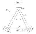
- FIGURE 1 is a schematic illustration of a ring laser gyroscope incorporating two non-reciprocal quantum well bias mirrors according to the present invention.
- FIGURE 2 is a schematic illustration of a quantum well boundary interface.
- FIGURE 4 is a cross-sectional view of a quantum well filter element according to the present invention.
- a ring laser gyroscope 10 is shown with one dielectric mirror 12 and two quantum well bias mirrors 14 according to the present invention.
- Three rays 16,18,20 are also shown with each ray representing two laser beams traveling in opposite directions 22,24 around a triangular path within the ring laser gyroscope 10.
- quantum well bias mirror 14 When quantum well bias mirror 14 is energized with an electric field and quantum well bias mirror 14' is unenergized, the two laser beams travel the path labeled 16-20.
- quantum well bias mirror 14' is energized with an electric field and quantum well bias mirror 14 is unenergized, the two laser beams travel the path labeled 16'-20'.
- This dual action of the quantum well bias mirrors 14 causes a phase shift between the two laser beams, while leaving the total path length around the ring cavity 10 unchanged.
- non-reciprocal phase shift effects are produced by the mirrors 14 which cause the counter-propagating beams to split apart and oscillate at different frequencies, with the magnitude of the frequency split being dependent among other things upon the thickness of a quantum well structure within each quantum well bias mirror 14.
- a quantum well structure is formed within each quantum well bias mirror 14 to modulate the phase of the counter-propagating beams in the ring laser gyroscope 10.
- the index of refraction of the quantum well structure can be changed by applying a voltage across it. A change in the index of refraction of the quantum well structure will detune the quantum well bias mirror 14 so that it appears as if an incident beam has traveled a greater distance into the mirror stack. By varying the voltage you may vary the path of the beams in the ring laser gyroscope cavity 10, while leaving the total path length of the beams around the ring cavity 10 unchanged.
- the incident laser beam 28 is transmitted straight through the quantum well region 26 when no electric field is applied to the region 26.
- an electric field is applied to the quantum well region 26 parallel to the plane of incidence of the laser beam 28, a dielectric boundary is formed along that plane by a corresponding decrease in the refractive index of the quantum well region 26.
- the incident laser beam 28 is reflected from the surface of the quantum well region 26.
- an effective oscillating phase shift can be generated between a pair of incident laser beams. This concept is the basis for the use of the quantum well bias mirrors 14 in the ring laser gyroscope 10.
- This quantum well bias mirror 30 which is used to achieve a non-reciprocal phase shift in a ring laser gyroscope, is comprised of a supporting substrate member 32, a multiple quantum well filter layer 34, and a plurality of dielectric layers 36 and 38 having alternating high and low refractive indices, respectively.
- Each of the dielectric layers 36,38 has a phase thickness corresponding to the wavelength and the path of light passing therethrough so that light reflected from the bottom surface of each layer is in phase with light reflected from the top surface of each layer.
- This quantum well filter layer 34 is comprised of alternating layers of high index of refraction quantum well material 40 and low index of refraction dielectric material 42 sandwiched between a pair of electrodes 44.
- the electrodes 44 provide a means for creating an electric field across the quantum well and dielectric material layers 40,42 with a voltage differential applied thereto.
- a common quantum well material 40 is an Aluminum/Gallium/Indium/Phosphorus composition, although other material compositions having an overall high index of refraction are equally applicable.
- the low index of refraction dielectric material 42 is typically Silicon/Dioxide, or a similar dielectric material having a low index of refraction.
- the electrodes 44 can be fabricated from a variety of conductive materials such as Gold, but must be thin to allow light to be transmitted therethrough. It should be noted that excellent filtering characteristics are obtained when between fifteen and twenty-one layers of both the quantum well material 40 and the low refractive index dielectric material 42 are used.
- the index of refraction of the quantum well material 40 and the index of refraction of the dielectric material 42 are chosen to give a resulting edge filter as shown in Figure 5.
- the quantum well filter layer 34 When the quantum well filter layer 34 is energized with an electric field, the quantum well filter layer 34 is highly reflective and is represented by a reflective region 46 in the graph.
- the quantum well filter layer 34 When the quantum well filter layer 34 is not energized with an electric field, the quantum well filter layer 34 is highly transparent and is represented by a transparent region 48 in the graph.
- the wavelength ratio ( ⁇ 0 / ⁇ ) is determined by the wavelength of the incident light beams through the incident medium ( ⁇ 0 ) and the apparent wavelength of the incident light beams through the quantum well filter layer ( ⁇ ).
- a similar quantum well bias mirror may be fabricated having a quantum well region that reflects light when no electric field is applied thereto and transmits light when an electric field is applied thereto.
- Such a similar quantum well bias mirror would be fabricated in essentially the same manner as described above, although different materials and/or different material thicknesses would be required for the quantum well filter layer.
Landscapes
- Physics & Mathematics (AREA)
- Optics & Photonics (AREA)
- Engineering & Computer Science (AREA)
- Electromagnetism (AREA)
- General Physics & Mathematics (AREA)
- Nonlinear Science (AREA)
- Power Engineering (AREA)
- Radar, Positioning & Navigation (AREA)
- Remote Sensing (AREA)
- Plasma & Fusion (AREA)
- Gyroscopes (AREA)
- Lasers (AREA)
Claims (17)
- Un miroir de polarisation à puits quantique (30) destiné à la modulation de phase de faisceaux à contre-propagation dans un gyroscope annulaire à laser de manière à réduire ou éliminer les effets de verrouillage (ou blocage) interne, ledit miroir de polarisation à puits quantique (30) comportant :caractérisé en ce qu'il comporte, de plus :un substrat (32) ; etune pluralité de couches diélectriques (36, 38) disposées sur le dessus dudit substrat (32), ladite pluralité de couches diélectriques (36, 38) ayant des indices de réfraction alternativement élevés et bas de manière à constituer une structure analogue à un miroir,
une couche filtrante multiple pour puits quantique (34) déposée sur le dessus de ladite pluralité de couches diélectriques (36, 38), l'indice de réfraction de ladite couche filtrante multiple pour filtre quantique (34) étant susceptible d'être modifié par application à celle-ci d'un champ électrique, le rayonnement incident qui est transmis par ladite couche multiple pour puits quantique (34) étant réfléchi par la surface de ladite pluralité de couches diélectriques (36, 38) de manière telle que les oscillations dans l'application dudit champ électrique entraínent des oscillations dans la longueur du trajet dudit rayonnement incident. - Le miroir de polarisation à puits quantique de la revendication 1, dans lequel ledit substrat (32) peut être fabriqué en une variété de matériaux transparents rigides tels que le quartz.
- Le miroir de polarisation à puits quantique de la revendication 1, dans lequel chacune des couches de ladite pluralité de couches diélectriques (36, 38) a une épaisseur de phase correspondant à la longueur d'onde de ladite radiation incidente.
- Le miroir de polarisation à puits quantique de la revendication 3, dans lequel ladite pluralité de couches diélectriques (36, 38) peut être réalisé en une variété de matériaux diélectriques ayant des indices de réfraction élevés et bas tels que le dioxyde de titane et le dioxyde de silicium, respectivement.
- Le miroir de polarisation à puits quantique de la revendication 1, dans lequel ladite couche filtrante multiple (34) pour puits quantique se compose de :une pluralité de couches alternées (40, 42) de matières pour puits quantique ayant un indice de réfraction élevé et de matières diélectriques à bas indice de réfraction ; et d'une paire d'électrodes (44) délimitant ladite pluralité de couches alternées (40, 42) de matières pour puits quantique ayant un indice de réfraction élevé et de matières diélectriques à bas indice de réfraction, de manière telle que ledit champ électrique puisse être appliqué à travers ladite pluralité de couches alternées (40, 42) de matières pour puits quantique à haut indice de réfraction et de matières diélectriques à bas indice de réfraction.
- Le miroir de polarisation à puits quantique de la revendication 5, dans lequel ledit champ électrique est appliqué dans une direction perpendiculaire aux surfaces de ladite pluralité de couches alternées (40, 42) de matières pour puits quantique à haut indice de réfraction et de matières diélectriques à bas indice de réfraction.
- Le miroir de polarisation à puits quantique de la revendication 6, dans lequel chacune des couches de ladite pluralité de couches (40) de matières pour puits quantique à haut indice de réfraction a une propriété qui permet à un rayonnement incident d'être réfléchi par elle, à l'application à celle-ci dudit champ électrique, tout en permettant par ailleurs audit rayonnement incident d'être transmis par elle.
- Le miroir de polarisation à puits quantique de la revendication 6, dans lequel chacune des couches de ladite pluralité de couches de matières pour puits quantique à haut indice de réfraction (40) a une propriété qui permet à un rayonnement incident d'être transmis à travers elle et réfléchi par les surfaces des couches de ladite pluralité de couches diélectriques (36, 38) à l'application à celles-ci dudit champ électrique, tout en permettant par ailleurs audit rayonnement incident d'être réfléchi par elle.
- Le miroir de polarisation à puits quantique de l'une des revendications 7 ou 8, dans lequel ladite pluralité de couches de matières pour puits quantique à haut indice de réfraction (40) peut être fabriquée en une matière ayant un indice de réfraction global élevé telle qu'une composition aluminium / gallium / indium / phosphore.
- Le miroir de polarisation à puits quantique de la revendication 6, dans lequel chacune des couches de ladite pluralité de couches diélectriques à bas indice de réfraction (42) a une épaisseur de phase correspondant à la longueur d'onde dudit rayonnement incident.
- Le miroir de polarisation à puits quantique de la revendication 10, dans lequel ladite pluralité de couches diélectriques à bas indice de réfraction (42) peut être réalisée en une variété de matières ayant un bas indice de réfraction telles que le dioxyde de silicium.
- Le miroir de polarisation à puits quantique de la revendication 6, dans lequel ladite paire d'électrodes (44) délimite ladite pluralité de couches alternées (40, 42) de matières pour puits quantique à haut indice de réfraction et de matières diélectriques à bas indice de réfraction par de minces couches de matières conductrices, de telle sorte que le rayonnement incident puisse être transmis à travers elles.
- Le miroir de polarisation à puits quantique de la revendication 12, dans lequel ladite paire d'électrodes (44) peut être réalisée en une variété de matières conductrices telles que l'or.
- Un gyroscope annulaire à laser (10) comprenant :caractérisé en ce que ledit élément multicouches contient une structure filtrante à puits quantique (34).une cavité optique en boucle fermée contenant un milieu pour création de laser actif en vue de donner naissance à des faisceaux lumineux à contre-propagation le long d'un trajet fermé à l'intérieur de ladite cavité optique en boucle ;un élément multicouches (32, 34, 36, 38) réflecteur de la lumière et polarisant la fréquence en vue de créer un décalage de phase différentiel entre ledits faisceaux lumineux à contre propagation,
- Le gyroscope annulaire à laser de la revendication 14, dans lequel ledit élément multicouches réflecteur de lumière et polarisant la fréquence (32, 34, 36, 38) se compose de :un substrat (32) ;une pluralité de couches diélectriques (36, 38) formées sur le dessus dudit substrat (32), ladite pluralité de couches diélectriques (36, 38) ayant des indices de réfraction alternativement élevés et bas de manière à créer une structure fortement réflectrice semblable à un miroir; etune couche filtrante (34) multicouches pour puits quantique formée sur le dessus de ladite pluralité de couches diélectriques (36, 38), ladite couche filtrante (34) multicouches pour puits quantique ayant une propriété qui permette aux faisceaux lumineux à contre-propagation d'être transmis à travers elle et réfléchie par les surfaces de ladite pluralité de couche diélectriques (36, 38) à l'application à celle-ci d'un champ électrique, tout en permettant par ailleurs auxdits faisceaux lumineux à contre-propagation d'être réfléchis par elle, de manière telle que des oscillations dans l'application dudit champ électrique ont pour effet de conférer ledit décalage de phase différentiel auxdits faisceaux lumineux à contre-propagation.
- Le gyroscope annulaire à laser de la revendication 14, dans lequel ledit élément multicouches (32, 34, 36, 38) réflecteur de lumière et polarisant la fréquence se compose de :un substrat (32) ;une pluralité de couches diélectriques (36, 38), formées sur le dessus dudit substrat (32), ladite pluralité de couches diélectriques ayant des indices de réfraction alternativement élevés et bas de manière à créer une structure fortement réflectrice semblable à un miroir ; etune couche filtrante (34) multicouches pour puits quantique formée sur le dessus de ladite pluralité de couches diélectriques (36, 38), ladite couche filtrante (34) multicouches pour puits quantique ayant une propriété qui permette auxdits faisceaux lumineux à contre-propagation d'être réfléchie par elle à l'application à celle-ci d'un champ électrique, tout en permettant par ailleurs auxdits faisceaux lumineux à contre-propagation d'être transmis par elle et réfléchis par les surfaces de ladite pluralité de couches diélectriques (36, 38), de manière telle que des oscillations dans l'application dudit champ électrique ont pour effet de conférer ledit décalage de phase auxdits faisceaux lumineux à contre-propagation.
- Le gyroscope annulaire à laser de l'une des revendications 15 ou 16, dans lequel ladite couche filtrante (34) multicouches pour puits quantique se compose de :de manière telle que ledit champ électrique puisse être appliqué à travers ladite pluralité de couches alternées (40, 42) de matières pour puits quantique à haut indice de réfraction et de matières diélectriques à bas indice de réfraction.une pluralité de couches alternées (40, 42) en matières pour puits quantique à haut indice de réfraction et de matières diélectriques à bas indice de réfraction ; et d'une paire d'électrodes (44) délimitant ladite pluralité de couches alternées (40, 42) de matières pour puits quantique à haut indice de réfraction et de matières diélectriques à bas indice de réfraction,
Applications Claiming Priority (3)
| Application Number | Priority Date | Filing Date | Title |
|---|---|---|---|
| US08/099,992 US5416583A (en) | 1993-07-30 | 1993-07-30 | Quantum well bias mirror for phase modulation in a ring laser gyroscope |
| US99992 | 1993-07-30 | ||
| PCT/US1994/008541 WO1995004255A1 (fr) | 1993-07-30 | 1994-07-26 | Miroir de polarisation a puits quantique destine a la modulation de phase d'un gyrolaser annulaire |
Publications (2)
| Publication Number | Publication Date |
|---|---|
| EP0711403A1 EP0711403A1 (fr) | 1996-05-15 |
| EP0711403B1 true EP0711403B1 (fr) | 1998-10-07 |
Family
ID=22277572
Family Applications (1)
| Application Number | Title | Priority Date | Filing Date |
|---|---|---|---|
| EP94924515A Expired - Lifetime EP0711403B1 (fr) | 1993-07-30 | 1994-07-26 | Miroir de polarisation a puits quantique destine a la modulation de phase d'un gyrolaser annulaire |
Country Status (4)
| Country | Link |
|---|---|
| US (1) | US5416583A (fr) |
| EP (1) | EP0711403B1 (fr) |
| JP (1) | JPH09504653A (fr) |
| WO (1) | WO1995004255A1 (fr) |
Families Citing this family (10)
| Publication number | Priority date | Publication date | Assignee | Title |
|---|---|---|---|---|
| US5548602A (en) * | 1994-06-30 | 1996-08-20 | Honeywell Inc. | Method and structure for reflecting 633 nm radiation while eliminating 650 nm radiation in ring laser gyro mirrors |
| US5694412A (en) * | 1996-04-08 | 1997-12-02 | He Holdings Inc. | Epitaxial visible-light-emitting devices with light extracted through the substrate and method of making same |
| US5701327A (en) * | 1996-04-30 | 1997-12-23 | Lucent Technologies Inc. | Saturable Bragg reflector structure and process for fabricating the same |
| DE19828319C2 (de) * | 1998-06-25 | 2000-08-31 | Daimler Chrysler Ag | Verfahren zum Betrieb eines diodengepumpten Festkörper-Ringlaserkreisels und Festkörper-Ringlaserkreisel |
| US6751044B1 (en) * | 1999-10-29 | 2004-06-15 | Maxtor Corporation | Method and apparatus for reading a clock track with a magneto-optical clock head using the transverse Kerr effect |
| FR2825463B1 (fr) * | 2001-05-30 | 2003-09-12 | Thales Sa | Gyrometre laser etat solide comportant un bloc resonateur |
| GB2391692A (en) | 2002-08-08 | 2004-02-11 | Univ Bristol | A lasing device with a ring cavity |
| TWI329208B (en) * | 2003-06-03 | 2010-08-21 | Oerlikon Trading Ag | Optical substrate for enhanced detectability of fluorescence |
| KR100949571B1 (ko) * | 2008-01-21 | 2010-03-25 | 포항공과대학교 산학협력단 | 광양자테 레이저 및 그 제조 방법 |
| CN103959013A (zh) | 2011-09-29 | 2014-07-30 | 斯维尔系统 | 锁定减少的基于mems的环形激光陀螺仪 |
Family Cites Families (13)
| Publication number | Priority date | Publication date | Assignee | Title |
|---|---|---|---|---|
| US3528029A (en) * | 1966-09-20 | 1970-09-08 | Sperry Rand Corp | Ring laser having synchronized phase modulators for inhibiting mode pulling |
| US3851973A (en) * | 1972-01-03 | 1974-12-03 | Sperry Rand Corp | Ring laser magnetic bias mirror compensated for non-reciprocal loss |
| US4627732A (en) * | 1981-05-20 | 1986-12-09 | Raytheon Company | Mode discrimination apparatus |
| US4410276A (en) * | 1981-06-15 | 1983-10-18 | The Singer Company | Ring laser gyroscope with doppler mirrors |
| US4525687A (en) * | 1983-02-28 | 1985-06-25 | At&T Bell Laboratories | High speed light modulator using multiple quantum well structures |
| US4846574A (en) * | 1983-06-24 | 1989-07-11 | Honeywell Inc. | Retroreflected antilocking feedback |
| US4821282A (en) * | 1985-12-27 | 1989-04-11 | Honeywell Inc. | Mirror assembly for lasers |
| US4904045A (en) * | 1988-03-25 | 1990-02-27 | American Telephone And Telegraph Company | Grating coupler with monolithically integrated quantum well index modulator |
| US5007695A (en) * | 1989-09-29 | 1991-04-16 | Honeywell Inc. | Fiber optic phase modulator using electro-optic material in evanescent field |
| US5116131A (en) * | 1990-04-19 | 1992-05-26 | Litton Systems, Inc. | Mirror transducer assembly for ring laser gyroscopes |
| FR2661784B1 (fr) * | 1990-05-02 | 1992-07-03 | Thomson Csf | Laser de puissance a miroir actif. |
| JPH04107976A (ja) * | 1990-08-28 | 1992-04-09 | Mitsubishi Electric Corp | 半導体レーザ装置 |
| US5137358A (en) * | 1991-02-05 | 1992-08-11 | Northrop Corporation | Ring laser gyro having two magnetic mirrors |
-
1993
- 1993-07-30 US US08/099,992 patent/US5416583A/en not_active Expired - Lifetime
-
1994
- 1994-07-26 WO PCT/US1994/008541 patent/WO1995004255A1/fr not_active Ceased
- 1994-07-26 EP EP94924515A patent/EP0711403B1/fr not_active Expired - Lifetime
- 1994-07-26 JP JP7505978A patent/JPH09504653A/ja not_active Ceased
Also Published As
| Publication number | Publication date |
|---|---|
| US5416583A (en) | 1995-05-16 |
| EP0711403A1 (fr) | 1996-05-15 |
| WO1995004255A1 (fr) | 1995-02-09 |
| JPH09504653A (ja) | 1997-05-06 |
Similar Documents
| Publication | Publication Date | Title |
|---|---|---|
| US4887900A (en) | Polarization maintaining fiber interferometer and method for source stabilization | |
| US4915503A (en) | Fiber optic gyroscope with improved bias stability and repeatability and method | |
| US4037929A (en) | Optical projection device and an optical reader incorporating this device | |
| US3851973A (en) | Ring laser magnetic bias mirror compensated for non-reciprocal loss | |
| US4525028A (en) | Enhanced magnetic mirror | |
| EP0711403B1 (fr) | Miroir de polarisation a puits quantique destine a la modulation de phase d'un gyrolaser annulaire | |
| US4968136A (en) | Ring laser gyro and magnetic mirror therefor | |
| JP2696306B2 (ja) | 光学要素のための多層コーティング | |
| JPH07209607A (ja) | 光アイソレータ | |
| NL8202002A (nl) | Optisch stelsel. | |
| US4494873A (en) | Electromagnetic wave reflections absorber | |
| JPH0514251B2 (fr) | ||
| US5097481A (en) | Gas laser having two longitudinal modes of laser oscillation | |
| US5978141A (en) | Optical mirror particularly suited for a quantum well mirror | |
| US4219275A (en) | Ring laser having magnetic isolation of counter-propagating light waves | |
| JP2671335B2 (ja) | レーザ光源 | |
| JPH07325276A (ja) | 偏波無依存光制御素子 | |
| US5448396A (en) | Photo isolator | |
| JPH0613683A (ja) | 二つの磁気ミラーを有するリングレーザージャイロ | |
| US3730609A (en) | Thermally compensated ultrasonic light modulator | |
| US4556320A (en) | Laser rotation rate sensor | |
| US5373360A (en) | Method and apparatus for reducing rotational bias in a ring laser | |
| JP3365648B2 (ja) | 光学ミラー | |
| JPS62500209A (ja) | リングレ−ザ−ジャイロの磁場変化感応度低下装置 | |
| US4563092A (en) | Laser rotation rate sensor |
Legal Events
| Date | Code | Title | Description |
|---|---|---|---|
| PUAI | Public reference made under article 153(3) epc to a published international application that has entered the european phase |
Free format text: ORIGINAL CODE: 0009012 |
|
| 17P | Request for examination filed |
Effective date: 19960228 |
|
| AK | Designated contracting states |
Kind code of ref document: A1 Designated state(s): FR GB |
|
| 17Q | First examination report despatched |
Effective date: 19970430 |
|
| GRAG | Despatch of communication of intention to grant |
Free format text: ORIGINAL CODE: EPIDOS AGRA |
|
| GRAH | Despatch of communication of intention to grant a patent |
Free format text: ORIGINAL CODE: EPIDOS IGRA |
|
| GRAH | Despatch of communication of intention to grant a patent |
Free format text: ORIGINAL CODE: EPIDOS IGRA |
|
| GRAA | (expected) grant |
Free format text: ORIGINAL CODE: 0009210 |
|
| AK | Designated contracting states |
Kind code of ref document: B1 Designated state(s): FR GB |
|
| ET | Fr: translation filed | ||
| PLBE | No opposition filed within time limit |
Free format text: ORIGINAL CODE: 0009261 |
|
| STAA | Information on the status of an ep patent application or granted ep patent |
Free format text: STATUS: NO OPPOSITION FILED WITHIN TIME LIMIT |
|
| 26N | No opposition filed | ||
| REG | Reference to a national code |
Ref country code: GB Ref legal event code: IF02 |
|
| PGFP | Annual fee paid to national office [announced via postgrant information from national office to epo] |
Ref country code: GB Payment date: 20050701 Year of fee payment: 12 |
|
| PGFP | Annual fee paid to national office [announced via postgrant information from national office to epo] |
Ref country code: FR Payment date: 20050728 Year of fee payment: 12 |
|
| PG25 | Lapsed in a contracting state [announced via postgrant information from national office to epo] |
Ref country code: GB Free format text: LAPSE BECAUSE OF NON-PAYMENT OF DUE FEES Effective date: 20060726 |
|
| GBPC | Gb: european patent ceased through non-payment of renewal fee |
Effective date: 20060726 |
|
| REG | Reference to a national code |
Ref country code: FR Ref legal event code: ST Effective date: 20070330 |
|
| PG25 | Lapsed in a contracting state [announced via postgrant information from national office to epo] |
Ref country code: FR Free format text: LAPSE BECAUSE OF NON-PAYMENT OF DUE FEES Effective date: 20060731 |