EP0711522B1 - Verriegelungs-/Entriegelungsventil eines Decksel auf einem Gefäss - Google Patents
Verriegelungs-/Entriegelungsventil eines Decksel auf einem Gefäss Download PDFInfo
- Publication number
- EP0711522B1 EP0711522B1 EP95420310A EP95420310A EP0711522B1 EP 0711522 B1 EP0711522 B1 EP 0711522B1 EP 95420310 A EP95420310 A EP 95420310A EP 95420310 A EP95420310 A EP 95420310A EP 0711522 B1 EP0711522 B1 EP 0711522B1
- Authority
- EP
- European Patent Office
- Prior art keywords
- pressure
- locking
- valve
- piston
- cylinder
- Prior art date
- Legal status (The legal status is an assumption and is not a legal conclusion. Google has not performed a legal analysis and makes no representation as to the accuracy of the status listed.)
- Expired - Lifetime
Links
- 238000010411 cooking Methods 0.000 claims abstract description 40
- 238000004891 communication Methods 0.000 claims description 9
- 238000006073 displacement reaction Methods 0.000 claims description 7
- 230000000694 effects Effects 0.000 claims description 6
- 238000013519 translation Methods 0.000 description 5
- 238000010276 construction Methods 0.000 description 4
- 208000031968 Cadaver Diseases 0.000 description 3
- 238000007789 sealing Methods 0.000 description 3
- 230000008901 benefit Effects 0.000 description 2
- 238000006243 chemical reaction Methods 0.000 description 2
- 230000007246 mechanism Effects 0.000 description 2
- 239000012528 membrane Substances 0.000 description 2
- 239000002245 particle Substances 0.000 description 2
- 230000002093 peripheral effect Effects 0.000 description 2
- 230000009471 action Effects 0.000 description 1
- 230000015572 biosynthetic process Effects 0.000 description 1
- 230000002860 competitive effect Effects 0.000 description 1
- 230000000295 complement effect Effects 0.000 description 1
- 230000000994 depressogenic effect Effects 0.000 description 1
- 230000003100 immobilizing effect Effects 0.000 description 1
- 238000003780 insertion Methods 0.000 description 1
- 230000037431 insertion Effects 0.000 description 1
- 238000012423 maintenance Methods 0.000 description 1
- 239000002184 metal Substances 0.000 description 1
- 239000007769 metal material Substances 0.000 description 1
- 230000004048 modification Effects 0.000 description 1
- 238000012986 modification Methods 0.000 description 1
- 230000000750 progressive effect Effects 0.000 description 1
- 229910001220 stainless steel Inorganic materials 0.000 description 1
- 239000010935 stainless steel Substances 0.000 description 1
- 238000003466 welding Methods 0.000 description 1
Images


Classifications
-
- A—HUMAN NECESSITIES
- A47—FURNITURE; DOMESTIC ARTICLES OR APPLIANCES; COFFEE MILLS; SPICE MILLS; SUCTION CLEANERS IN GENERAL
- A47J—KITCHEN EQUIPMENT; COFFEE MILLS; SPICE MILLS; APPARATUS FOR MAKING BEVERAGES
- A47J27/00—Cooking-vessels
- A47J27/08—Pressure-cookers; Lids or locking devices specially adapted therefor
- A47J27/09—Safety devices
-
- A—HUMAN NECESSITIES
- A47—FURNITURE; DOMESTIC ARTICLES OR APPLIANCES; COFFEE MILLS; SPICE MILLS; SUCTION CLEANERS IN GENERAL
- A47J—KITCHEN EQUIPMENT; COFFEE MILLS; SPICE MILLS; APPARATUS FOR MAKING BEVERAGES
- A47J27/00—Cooking-vessels
- A47J27/08—Pressure-cookers; Lids or locking devices specially adapted therefor
- A47J27/09—Safety devices
- A47J27/092—Devices for automatically releasing pressure before opening
Definitions
- the present invention relates to the general technical field of devices for locking / unlocking a cover on a tank to form a cooking container, preferably under pressure.
- the present invention relates to a valve for locking / unlocking a cover on a vessel to form a pressure cooking vessel, comprising means for indicating the level of pressure.
- a locking valve for a cover for a pressure cooking container constituted by a first axially movable element capable of adopting a sealed locking position in which the container lid cannot be opened, or a non-sealed position of unlocking in which the container lid can be opened, a sliding cylinder being provided in the lower part of the valve so that said cylinder is in communication with the ambient pressure of the container.
- Pressure cooking vessels generally comprise a locking / unlocking device or closing means intended to ensure the closing by locking of a lid on a vessel, so as to form a pressure cooking vessel such as a pressure cooker .
- Pressure cookers are known, for example, the lid of which comprises means of opening / closing of the bayonet type, with jaws, etc.
- Several types of known safety means applicable in multiple variants provide elements with relative movement (angular, longitudinal or axial), comprising locking means, most often openings or lights, which line up when the cover is properly closed.
- a locking element can then be positioned, for example under the effect of the pressure being established in the cooking chamber, in the locking means, immobilizing the elements relative to each other and preventing the thus activates the mechanism for opening the cover, either by taking it with a fixed element of the tank, or by holding the jaws in the closed position, etc.
- Document BE 806 483 describes for its part a valve for locking / unlocking a cover on a tank according to the preamble of claim 1.
- This device comprises a piston movable axially between a low position in which the cover is free and a position high locking where the cover cannot be removed.
- the means used in this device mean that it remains vulnerable under certain conditions, in particular in the following cases:
- the safety of the device may be affected; pressure could build up in the enclosure despite the lid not being locked; if the holes 13 as well as the hole located at the base of the jacket 12 (under the piston) become blocked simultaneously, the safety of the device can also be affected; the piston can remain in the low position despite the establishment of pressure in the enclosure. The user can then open the cover with the risks that this implies.
- the only mobile element the piston, serves both as a locking means and as a means of indicating the pressure level.
- the body is fixed. It does not perform a locking function.
- the object of the present invention therefore aims to remedy the various drawbacks listed above, and to propose a new valve for locking / unlocking a cooking container making it possible to ensure simply and reliably, the correct position. closing means and complete and safe closing of the cover on the tank, while indicating to the user the pressure level reached in the cooking chamber.
- a locking valve for a lid for a pressure cooking container constituted by a first axially movable element capable of adopting a sealed locking position in which the lid of the container cannot be opened. , or a non-sealed unlocking position in which the container lid can be opened, a sliding cylinder being provided in the lower part of the valve so that said cylinder is in communication with the ambient pressure of the container, characterized in that said first axially movable element is the body of the valve which slides freely between said sealed locking position and said non-sealed unlocking position, said valve comprising a second element consisting of a piston, a piston rod s' extending axially from the piston and extending beyond the bottom of the cylinder by a pe rinsing provided at the bottom of the cylinder, a return means acting on the piston against the pressure prevailing in the enclosure, and an indication head disposed at the free end of the rod, the second element being axially movable relative to the first.
- the main elements are movable relative to each other: the body is axially movable relative to the cover and the piston is also movable relative to the body.
- the movable body is the key element concerning the security of the device, since it ensures the locking function. Its security is ensured, in particular by the absence of opening capable of being closed by a particle during cooking.
- This valve it is possible to avoid the rise in pressure beyond a determined safety threshold in the cooking chamber if the cover is incorrectly closed.
- This threshold could correspond for example to a pressure substantially equivalent to atmospheric pressure.
- the second element makes it possible to indicate on the one hand if the first element is in the locking or unlocking position and on the other hand, when said first element is in the locking position , at least one cooking pressure level. This provides completely independent locking and pressure level indication functions.
- the locking valve also comprises at least one discharge orifice provided in the wall of the cylinder, said orifice being placed in communication with the open end of the cylinder when the piston is subjected to a force.
- pressure corresponding to an overpressure level is defined according to the characteristics of the cooking article and the safety standards to be observed, in order to avoid any danger for the user.
- Such a pressure can correspond for example to a value corresponding to approximately twice the pressure of normal running.
- the indication head is capable of showing at least one low pressure indication mark and / or at least one high pressure indication mark, said marks being revealed by the displacement of the piston, in communication with the pressure of the enclosure and sliding under the effect of the pressure, the calibrated return means allowing the piston to assume a given position as a function of a given pressure level. This gives the possibility of indicating different pressure levels.
- a pressure cooking container comprising a locking valve, constituted by an axially movable element capable of adopting a sealed locking position in which the lid of the container cannot be opened, or a non-sealed unlocking position in which the container lid can be opened, a sliding cylinder being provided in the lower part of the valve so that said cylinder is in communication with the ambient pressure of the container, characterized in that that said axially movable element is the valve which slides freely between said sealed locking position and said non-sealed unlocking position, said valve comprising a piston movable axially in the cylinder under the effect of the pressure prevailing in the enclosure, a rod piston extending axially from the piston and extending beyond from the bottom of the cylinder by a hole provided at the bottom of the cylinder, a return means acting on the piston against the pressure prevailing in the enclosure, an indication head disposed at the free end of the rod, and in that the indication head allows to indicate on the one hand if the valve is in
- the invention makes it possible to simplify the construction of the cooking articles under pressure, to minimize the number of components and optimize the cost price.
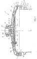
- Pressure cooking vessels generally comprise closing means intended to ensure the closing of a cover 1 on a tank 2, so as to form a cooking vessel, preferably under pressure, such as a pressure cooker.
- Figures 1 to 4 correspond to a first type of means for closing the cover.
- the locking valve according to the invention is applied in the first place to this type of closure as described below. Thereafter, the locking valve according to the invention is applied to a second type of closing means corresponding to Figures 5a, 5b and 5c. It is obvious that the locking valve according to the invention can be applied, without departing from the scope of the invention, to any type of closing means fulfilling a similar function.
- the container consists for example of a tank of substantially cylindrical shape, of axis of revolution x-x ', on which the cover 1 is intended to be attached in leaktight manner, for example by means of a gasket seal 3, for example a lip seal.
- the tank 2 is conventionally made from a metallic material such as stainless steel and provided with a thermally conductive bottom secured to the tank 2, for example by hot stamping.
- the tank also includes gripping members such as handles 5 fixed to the walls of the tank 2 by means of fastening tabs 6 and screws 7.
- the cover 1 comprises a profiled closure disc 8, provided at its periphery with a groove-shaped zone 9 serving as a seat for receiving the seal 3, and assuming with the latter the seal of the closure of the cover 1 .
- the closing disc 8 is provided with at least one bore 100 allowing the passage and the mounting of a locking valve 10, object of the present invention, mounted with axial free sliding in said bore between a low stop position (such as shown in Figure 4a for example), and a high stop position (as shown in Figure 4b for example).
- the vapor tightness between the locking valve 10 and the bore 100 is improved by the interposition of a seal 11, the latter being held in position by pressing on a flange 12 forming the lower external radial part of the locking valve 10.
- the cover 1 also comprises at least two jaws 15a, 15b, mounted radially movable on the closing disc 8 between a closing position of the cover 1 on the tank 2 ( Figures 1 and 2) and an open position ( Figure 3) .
- the jaws 15a, 15b are conventionally in the form of segments of U-shaped profiles adapted to the shape of the container, and in the case shown in the figures, in the form of arcs of circles of determined length.
- Each jaw 15 has a lower rim 16 and an upper rim 17 making it possible respectively to enclose the peripheral rim 2a of the tank 2 and the upper limit of the groove 9.
- Each jaw 15a, 15b is movably mounted on the cover by the intermediate of driving elements including associated driving arms 20a, 20b, diametrically opposite and secured by one end 21, for example by welding, of the upper edge 17.
- Each driving arm 20a, 20b is in the form of a metal profile for example rectilinear, of profile adapted to that of the closing disc 8 and of U-shaped cross section, whose core is turned towards the outside of the container and whose wings 22 also extend towards the outside of the container.
- the driving arms 20a, 20b have a sufficient length so that they can be superimposed, at least in part, during their radial displacement.
- the driving arms 20a, 20b are radially self-guided one inside the other, the arm 20a forming the male arm and the 20b forming the female arm, the male arm sliding in the female arm.
- the relative guidance of the arms 20a, 20b, is obtained by cooperation and friction of the wings 22 of each of the arms 20a, 20b.
- Such an assembly obviously makes it possible to reduce the risks of possible deformation during the radial sliding of each of the arms 20a, 20b, and to perfectly control the linear movement of each jaw 15a, 15b.
- Each driving arm, 20a, 20b is provided with a locking lumen 25a, 25b (FIG. 4a), formed through the core of each arm.
- the position of each lumen 25a, 25b is determined as a function of the length of each arm 20a, 20b so that the lumens 25a, 25b are in the alignment position when the jaws 15a, 15b, are in the closed position.
- the position of the lights 25a, 25b, as well as the position of the hole 100, and therefore of the valve 10 is chosen so that when the jaws 15a and 15b are in the closed position, the lights 25a, 25b, as well as the hole 100 are aligned.
- This arrangement allows the body 10c of the locking valve 10 according to the invention to occupy the determined position corresponding to the pressure prevailing in the container, and in particular to occupy its high position (FIG. 4b) in which the body 10c the valve 10 engages in each of the openings 25a, 25b, to lock the jaws in their closed position.
- a position is obviously acquired only when the jaws 15a, 15b, occupy precisely their closed position which alone allows the passage of the valve 10 simultaneously in the ports 25a, 25b.
- the body 10c of the locking valve 10 cannot rise, which generates a vapor leak out of the container preventing any rise in pressure.
- the guiding of the linear and radial movement of the driving arms 20a, 20b, is ensured by additional guiding means which are integral with the cover 1.
- the guide means are formed by a support piece 30 which encloses the driving arms 20a, 20b, over most of their length.
- the support part 30 is formed of a plate of U-shaped cross section enclosing and covering the driving arms 20a, 20b, the inner face of the core of the U being turned towards the closing disc 8.
- the plate support 30 is advantageously secured to the closing disc 8 by means of two anchor points 31, 32, located on either side of the longitudinal axis of the support plate 30.
- the anchor points 31, 32 may consist of fastening means such as screws, or on the contrary also serve as a seat for the passage of pressure regulation means.
- the support plate 30 in an inverted manner, the inner face of the support plate 30 being turned towards the outside of the container, the arms 20a, 20b, sliding one inside the other. as well as in said support plate. In this position, the support plate 30 encloses and supports the arms 20a, 20b.
- the guide means may consist of ramps or equivalent means, integral with or integral with the closing disc 8.
- the guide means assume, in addition to a function of additional aid for the linear sliding of the driving arms 20a, 20b, a function additional stiffening of the mechanical assembly ensuring the radial displacement of the jaws 15a, 15b.
- the displacement travel of the driving arms 20a, 20b, between each of their limit position, corresponding to the open and closed position of the jaws 15a, 15b, is limited by means of a slot 40, preferably formed in the male arm 20a, in which can move a lug 41 secured to the female arm 20b.
- the movement stroke of the arms 20a, 20b is thus limited by the abutment of the lug 41 against one or the other of the two ends of the slot 40.
- the support plate 30 includes a opening aligned with the openings 25a, 25b, as well as with the bore 100, allowing the displacement of the locking valve 10 according to the invention.
- Such an assembly allows the relative sliding of the driving arms 20a, 20b, when the body 10c of the locking valve 10 is in its low position, which simultaneously ensures the free movement of the jaws 15a, 15b.
- the driving arms 20a, 20b are brought back permanently to the closed position by an elastic return means constituted for example by a spring 45 interposed between two legs respectively secured to each of the driving arms 20a, 20b.
- the opening / closing device also comprises a means 50 for controlling the movement of the jaws 15a, 15b, making it possible to bring each jaw into one or the other of their fixed position.
- control means 50 the means constituting the jaw opening / closing device illustrated in FIG. 1, as well as the operation of this device are described in detail in European patent applications N ° 95420188.5 and 95420187.7 from the same applicant, the content is integrated into this application.
- control means 50 forms the gripping member of the cover 1 and consists of a control member 56 mounted movably in a substantially radial direction on the cover 1 and kinematically coupled with a control button 52 mounted movable on the cover 1 in a substantially axial direction.
- the cover 1 can have a covering plate 65 covering the entire mechanism, said plate being sandwiched between the support plate 30 and the knob 51.
- the operation of the opening / closing device is the following :
- the introduction of the cover 1 on the tank 2 requires the opening of the jaws 15a, 15b, and the radial actuation of the pusher 56 which makes it possible to slide the triangular actuation zone 58 which gradually engages by its sides the pins 41, 41b ( Figure 2).
- the progressive displacement of the pusher 56 makes it possible to progressively separate the driving elements and in particular the driving arms 20a, 20b, and simultaneously the jaws 15a, 15b.
- the translation of the pusher 56 in a radial direction therefore allows the translation of the two jaws 15a, 15b.
- the end of the translation is determined by the positioning of each lug 41, 41b, in the associated recesses 60a, 60b.
- the limit position of the jaws 15a, 15b is also determined by the abutment of the lug 41 against the end of the slot 40. In the position thus reached, the jaws 15a, 15b are in position stable opening and thus allow centering of the cover 1 on the edge of the tank 2.
- the closure of the container is obtained by pressing the palm of the hand on the pommel button 52 which is consequently actuated axially .
- Its insertion into the knob 51 causes the engagement of the engagement surface 54 with its complementary surface 55 formed on the push button 56, which will gradually recede in an external radial direction.
- the pins 41, 41b are first released from the recesses 60a, 60b, the jaws 15a, 15b, then being gradually drawn back towards each other towards their closed position.
- the return to this closed position is obtained by the return action of the spring 45 allowing the positioning of each jaw 15a, 15b, between the cover 1 and under the rim 2a of the tank 2.
- the pressure can now rise and cause the body 10c of the locking valve 10 to pass in its high position through the openings 25a, 25b, which in the closed position complete jaws 15a, 15b, are coaxial.
- the engagement of the body 10c of the locking valve 10 through the slots 25a, 25b makes it possible to lock in position each of the driving arms 20a, 20b, and simultaneously each corresponding jaw.
- a pressure rise is ensured in complete safety since the passage of the locking valve in the locking slots 25a, 25b, can only intervene if the drive arms 20a, 20b, and therefore the jaws 15a , 15b, are in the perfectly closed position.
- the locking valve 10 also opposes any radial movement of the jaws 15a, 15b.
- the radial and linear movement of the drive arms 15a, 15b is also obtained without risk of deformation due to the presence of a succession of guide means formed by the sliding of the inner arms to each other and by the support plate 30.
- the locking valve 10 (FIGS. 4a to 4e) comprises a body 10c, in which is provided a sliding cylinder 10a formed in the lower part of said body of the valve so as to communicate with the ambient pressure of the container.
- This return means 13a is for example constituted by a spring disposed axially between the piston and the bottom of the cylinder.
- the piston rod 13b extends axially beyond the bottom of the cylinder 10a by means of a hole provided at this location.
- the body 10c of the valve 10 according to this variant can slide freely between a high position (fig. 4b) and a low position (fig. 4a) as already described above.
- the sealing of the valve can also be achieved by means of a flexible membrane 11b of known type.
- the indication head 14 also includes indication marks, corresponding to given pressure levels prevailing in the enclosure. For example, a first mark 14a indicates a low pressure level; a second mark 14b indicates a high pressure level.
- a selector of known type FIGS. 4c and 4d
- Figure 4c illustrates the situation where the user selected low cooking pressure (selector in position 1 if the cooking article is fitted with such a selector).
- the piston 13 sinks slightly so as to release the "low pressure" mark 14a.
- the pressure in the enclosure can then be around 40 to 60 kPa, for example.
- FIG. 4d illustrates the situation where the user has selected high pressure cooking (selector in position 2 in the case where the cooking article is provided with such a selector).
- the piston 13 is pushed even further so as to release the "high pressure" mark 14b.
- the pressure of the enclosure can then correspond to a value being for example around 80 to 100 kPa.
- different reference marks corresponding to different pressure levels, can be provided in this way.
- FIG. 4e An alternative embodiment of the valve 10 according to the invention, illustrated in FIG. 4e, makes it possible to avoid any formation of overpressure in the cooking chamber.
- at least one discharge orifice 10b is provided. This orifice is located at the upper portion of the cylinder 10a.
- the piston 13 acting against the force exerted by the return means 13a reaches the position corresponding to the orifice 10b only in cases where the pressure of the enclosure tends to exceed a predetermined upper limit. In such a case, the piston would be pushed by the overpressure to the extreme position ( Figure 4e), allowing the pressure to be released through the released orifices.
- the return means pushes the piston back into the normal operating position, for example in "high pressure" mode.
- Such a variant is advantageous since it makes it possible to achieve a high level of operating safety, which is particularly sought after for this type of cooking container. It also becomes possible to remove one of the pressure relief valves, thereby simplifying the construction of the assembly and reducing its cost.
- valve 10 is mounted freely movable along the axis x-x '( Figure 5a). It can move between a low position, corresponding substantially to atmospheric pressure, and a high position illustrated in FIG. 5b, in which the seal 11b, for example a membrane of known type, allows the tight closure in the high position. .
- the O-ring has the advantage of making it easier to perform the safety valve function, as described in the previous embodiment.
- the indication of the pressure level using the head 14 is done in a similar manner to the previous embodiment.
Landscapes
- Engineering & Computer Science (AREA)
- Food Science & Technology (AREA)
- Cookers (AREA)
- Table Devices Or Equipment (AREA)
- Pens And Brushes (AREA)
- Devices For Use In Laboratory Experiments (AREA)
- Closures For Containers (AREA)
Claims (12)
- Verriegelungsventil (10) für einen Deckel eines Druckkochbehälters, gebildet durch ein axial bewegliches erstes Element, das eine dichte Verriegelungsstellung, in welcher der Deckel des Behälters nicht geöffnet werden kann, oder eine nichtdichte Entriegelungsstellung einnehmen kann, in welcher der Deckel des Behälters geöffnet werden kann, wobei in dem unteren Abschnitt des Ventils ein Verschiebezylinder (10a) so angeordnet ist, daß er sich in Verbindung mit dem Außendruck des Behälters befindet, dadurch gekennzeichnet, daß das axial bewegliche erste Element der Körper (10c) des Ventils (10) ist, der frei zwischen der dichten Verriegelungsstellung und der nichtdichten Entriegelungsstellung gleitet, wobei das Ventil ein zweites Element aufweist, das durch einen Kolben (13), eine Kolbenstange (13b), die sich axial von dem Kolben (13) ausgehend erstreckt und bis jenseits des Bodens des Zylinders (10a) durch eine Bohrung hindurch verlängert ist, die im Boden des Zylinders vorgesehen ist, ein Rückstellmittel (13a), das auf den Kolben (13) entgegen dem in dem Behälter herrschenden Druck wirkt, und durch einen Anzeigekopf (14) gebildet ist, das an dem freien Ende der Stange (13b) angeordnet ist, wobei das zweite Element bezüglich des ersten Elementes axial beweglich ist.
- Verriegelungsventil nach Anspruch 1, bei dem das zweite Element zum einen ermöglicht anzuzeigen, ob sich das erste Element (10a) in der Verriegelungsstellung oder in der Entriegelungsstellung befindet, und zum anderen ermöglicht, wenigstens ein Kochdruckniveau anzuzeigen, wenn sich das erste Element in der Verriegelungsstellung befindet.
- Verriegelungsventil nach einem der Ansprüche 1 und 2, bei dem die dichte Verriegelungsstellung der oberen Stellung des Körpers (10c) entspricht.
- Verriegelungsventil nach einem der Ansprüche 1 bis 3, bei dem die nichtdichte Entriegelungsstellung der unteren Stellung des Körpers (10c) entspricht.
- Verriegelungsventil nach einem der vorhergehenden Ansprüche, bei dem das zweite Element unter der Wirkung des in dem Behälter herrschenden und gegen den Kolben (13) wirkenden Drucks axial beweglich ist.
- Verriegelungsventil nach einem der vorhergehenden Ansprüche, bei dem der Verschiebezylinder (10a) in dem zweiten Element angeordnet ist.
- Verriegelungsventil nach einem der vorhergehenden Ansprüche, bei dem die Stellung des Anzeigekopfes (14) direkt vom Benutzer wahrnehmbar ist.
- Verriegelungsventil nach einem der vorhergehenden Ansprüche, bei dem das Rückstellmittel (13a) eine Feder ist, die in Abhängigkeit von den in dem Kochbehälter herrschenden Druckniveaus kalibriert ist.
- Verriegelungsventil nach einem der vorhergehenden Ansprüche, bei dem die Feder axial zwischen dem Kolben und dem Boden des Zylinders angeordnet ist.
- Verriegelungsventil nach einem der vorhergehenden Ansprüche, das auch wenigstens eine Ausströmöffnung (10b) aufweist, die in der Wand des Zylinders vorgesehen ist, wobei die Öffnung mit dem offenen Ende des Zylinders in Verbindung steht, wenn der Kolben einer Druckkraft ausgesetzt ist, die einem Überdruckniveau entspricht.
- Verriegelungsventil nach einem der vorhergehenden Ansprüche, bei dem der Anzeigekopf (14) wenigstens eine Anzeigemarke (14a) für hohen Druck und/oder wenigstens eine Anzeigemarke (14b) für niedrigem Druck erscheinen lassen kann, wobei die Marken mittels der Verstellung des Kolbens (13) freigelegt werden, der mit dem Druck des Behälters in Verbindung steht und unter der Wirkung dieses Drucks verstellt wird, wobei das kalibrierte Rückstellmittel (13a) dem Kolben ermöglicht, in Abhängigkeit von einem gegebenen Druckniveau eine gegebene Stellung einzunehmen.
- Druckkochbehälter mit einem Verriegelungsventil (10), gebildet durch ein axial bewegliches Element, das eine dichte Verriegelungsstellung, in welcher der Deckel des Behälters nicht geöffnet werden kann, oder eine nichtdichte Entriegelungsstellung einnehmen kann, in welcher der Deckel des Behälters geöffnet werden kann, wobei in dem unteren Abschnitt des Ventils ein Verschiebezylinder (10a) so angeordnet ist, daß der Zylinder mit dem Umgebungsdruck des Behälters in Verbindung steht, dadurch gekennzeichnet, daß das axial bewegliche Element der Körper des Ventils (10) ist, der frei zwischen der dichten Verriegelungsstellung und der nichtdichten Entriegelungsstellung verschiebbar ist, wobei das Ventil einen Kolben (13) aufweist, der in dem Verschiebezylinder unter der Wirkung des in dem Behälter herrschenden Drucks axial beweglich ist, eine Kolbenstange (13b), die sich axial von dem Kolben (13) aus erstreckt und bis jenseits des Bodens des Zylinders (10a) durch eine im Boden des Zylinders vorgesehene Bohrung hindurch verlängert ist, ein Rückstellmittel (13a), das auf den Kolben (13) entgegen dem in dem Behälter herrschenden Druck einwirkt, und einen Anzeigekopf (14), der an dem freien Ende der Stange (13b) angeordnet ist, und daß der Anzeigekopf zum einen anzeigen kann, ob sich das Ventil (10) in der Verriegelungsstellung oder der Entriegelungsstellung befindet, und zum anderen wenigstens ein Kochdruckniveau anzeigen kann, wenn sich das Ventil in der Verriegelungsstellung befindet.
Applications Claiming Priority (2)
| Application Number | Priority Date | Filing Date | Title |
|---|---|---|---|
| FR9413984 | 1994-11-10 | ||
| FR9413984 | 1994-11-10 |
Publications (2)
| Publication Number | Publication Date |
|---|---|
| EP0711522A1 EP0711522A1 (de) | 1996-05-15 |
| EP0711522B1 true EP0711522B1 (de) | 1997-05-02 |
Family
ID=9469034
Family Applications (1)
| Application Number | Title | Priority Date | Filing Date |
|---|---|---|---|
| EP95420310A Expired - Lifetime EP0711522B1 (de) | 1994-11-10 | 1995-11-10 | Verriegelungs-/Entriegelungsventil eines Decksel auf einem Gefäss |
Country Status (4)
| Country | Link |
|---|---|
| EP (1) | EP0711522B1 (de) |
| AT (1) | ATE152334T1 (de) |
| DE (1) | DE69500272T2 (de) |
| ES (1) | ES2101601T3 (de) |
Families Citing this family (4)
| Publication number | Priority date | Publication date | Assignee | Title |
|---|---|---|---|---|
| EP1985212A1 (de) * | 2007-04-25 | 2008-10-29 | Compania de Menaje Domestico SL | Druckanzeige- und Kontrollventil |
| CN102273922A (zh) * | 2011-06-17 | 2011-12-14 | 张鑫 | 一种带锅盖开合锁紧装置的高压锅 |
| FR3072552B1 (fr) * | 2017-10-24 | 2019-12-20 | Seb S.A. | Joint d'etancheite pour autocuiseur a fenetre d'extrusion et autocuiseur equipe d'un tel joint |
| DE102019220212A1 (de) * | 2019-12-19 | 2021-06-24 | Wmf Group Gmbh | Verschlussvorrichtung für einen Druckbehälter, Druckbehälter und Verwendung der Verschlussvorrichtung |
Family Cites Families (6)
| Publication number | Priority date | Publication date | Assignee | Title |
|---|---|---|---|---|
| FR1057543A (fr) * | 1952-05-30 | 1954-03-09 | Perfectionnements aux marmites sous pression | |
| BE806483A (nl) * | 1973-10-25 | 1974-04-25 | Tomado Nv | Automatische dekselbeveiliging voor drukvat |
| EP0139772B1 (de) * | 1983-08-25 | 1987-07-08 | AMC International Alfa Metalcraft Corporation AG | Dampfdruckkochtopf |
| DE3330656A1 (de) * | 1983-08-25 | 1985-03-14 | Alfa Institut für hauswirtschaftliche Produkt- und Verfahrens-Entwicklung GmbH, 6228 Eltville | Entlueftungs- und druckentlastungseinrichtung an einem dampfdruckkochtopf |
| FR2700825B1 (fr) * | 1993-01-28 | 1995-04-14 | Seb Sa | Dispositif de commande automatique d'une soupape à limitation de flux. |
| FR2705319B1 (fr) * | 1993-05-14 | 1995-07-07 | Seb Sa | Bouchon de sécurité à joint annulaire d'étanchéité déformable. |
-
1995
- 1995-11-10 ES ES95420310T patent/ES2101601T3/es not_active Expired - Lifetime
- 1995-11-10 DE DE69500272T patent/DE69500272T2/de not_active Expired - Lifetime
- 1995-11-10 AT AT95420310T patent/ATE152334T1/de not_active IP Right Cessation
- 1995-11-10 EP EP95420310A patent/EP0711522B1/de not_active Expired - Lifetime
Also Published As
| Publication number | Publication date |
|---|---|
| ES2101601T3 (es) | 1997-07-01 |
| EP0711522A1 (de) | 1996-05-15 |
| ATE152334T1 (de) | 1997-05-15 |
| DE69500272T2 (de) | 1997-09-25 |
| DE69500272D1 (de) | 1997-06-05 |
Similar Documents
| Publication | Publication Date | Title |
|---|---|---|
| EP0691096B1 (de) | Klauenverriegelungs/-entriegelungsvorrichtung eines Deckels auf einem Geschirr | |
| EP1535553B1 (de) | Druckgargerät mit einzelner Entspannungs- und Verriegelungsvorrichtung | |
| EP1032295B1 (de) | Vorrichtung zum verriegeln/entriegeln eines dampfdruck-kochtopfs mit bajonettverschluss | |
| EP0156669B1 (de) | Dampfdruckkochtopf mit Sicherheitsverriegelung des Deckels | |
| EP1547497B1 (de) | Haushaltsdampfdruckkochgerät mit verbesserter Verriegelungsvorrichtung | |
| FR2700825A1 (fr) | Dispositif de commande automatique d'une soupape à limitation de flux. | |
| EP1938717B1 (de) | Druckkochgerät mit einer Verriegelung | |
| FR2722078A1 (fr) | Dispositif de commande de l'ouverture et de la fermeture des machoires de verrouillage pour un recipient sous pression | |
| EP1634518B1 (de) | Druckkochgerät mit verbesserter Sicherheit | |
| EP1277427A1 (de) | Dampfdruck-Kochtopf mit einem kalibrierten Entlüftungsventil | |
| FR3082717A1 (fr) | Autocuiseur muni d'une butee pour couvercle | |
| EP0711522B1 (de) | Verriegelungs-/Entriegelungsventil eines Decksel auf einem Gefäss | |
| FR2796543A1 (fr) | Soupape de securite pour un autocuiseur a trou d'homme | |
| EP1844685B1 (de) | Druckkochgerät mit verstellbarem Sollwert und überwachter Dekompression | |
| EP1568301B1 (de) | Haushaltsdampfdruckkochgerät für Nahrung mit Öffnungssicherheitssystem | |
| EP2702907B1 (de) | Deckel für Dampfdruckkochtopf mit vereinfachter Konstruktion und Dampfdruckkochtopf mit solchem Deckel. | |
| BE1005841A3 (fr) | Coupleur de securite pour robinet de recipient de fluide sous pression. | |
| EP1289394B1 (de) | Verriegelungsvorrichtung und entriegelungsvorrichtung eines deckels auf einem topf, und dampfdruckkochtopf | |
| FR2816491A1 (fr) | Dispositif de verrouillage / deverrouillage d'un couvercle sur une cuve, et recipient de cuisson sous pression comportant un tel dispositif | |
| EP1363087B1 (de) | Sammler unter veränderlichem Druck, insbesondere für Verflüssiger | |
| EP1317636B1 (de) | Druckminderungsventil zur schnellmontage auf eine gasflasche | |
| EP0433146A1 (de) | Wassereinspritzvorrichtung für Dampfbügeleisen mit solch einer Vorrichtung | |
| FR3095489A1 (fr) | Valve de gonflage et de dégonflage pour produit gonflable |
Legal Events
| Date | Code | Title | Description |
|---|---|---|---|
| PUAI | Public reference made under article 153(3) epc to a published international application that has entered the european phase |
Free format text: ORIGINAL CODE: 0009012 |
|
| AK | Designated contracting states |
Kind code of ref document: A1 Designated state(s): AT CH DE ES FR IT LI PT |
|
| 17P | Request for examination filed |
Effective date: 19960508 |
|
| GRAG | Despatch of communication of intention to grant |
Free format text: ORIGINAL CODE: EPIDOS AGRA |
|
| 17Q | First examination report despatched |
Effective date: 19960718 |
|
| GRAH | Despatch of communication of intention to grant a patent |
Free format text: ORIGINAL CODE: EPIDOS IGRA |
|
| GRAH | Despatch of communication of intention to grant a patent |
Free format text: ORIGINAL CODE: EPIDOS IGRA |
|
| GRAA | (expected) grant |
Free format text: ORIGINAL CODE: 0009210 |
|
| AK | Designated contracting states |
Kind code of ref document: B1 Designated state(s): AT CH DE ES FR IT LI PT |
|
| REF | Corresponds to: |
Ref document number: 152334 Country of ref document: AT Date of ref document: 19970515 Kind code of ref document: T |
|
| REG | Reference to a national code |
Ref country code: CH Ref legal event code: EP |
|
| REF | Corresponds to: |
Ref document number: 69500272 Country of ref document: DE Date of ref document: 19970605 |
|
| REG | Reference to a national code |
Ref country code: CH Ref legal event code: NV Representative=s name: MOINAS KIEHL SAVOYE & CRONIN |
|
| REG | Reference to a national code |
Ref country code: ES Ref legal event code: FG2A Ref document number: 2101601 Country of ref document: ES Kind code of ref document: T3 |
|
| REG | Reference to a national code |
Ref country code: PT Ref legal event code: SC4A Free format text: AVAILABILITY OF NATIONAL TRANSLATION Effective date: 19970716 |
|
| PLBE | No opposition filed within time limit |
Free format text: ORIGINAL CODE: 0009261 |
|
| STAA | Information on the status of an ep patent application or granted ep patent |
Free format text: STATUS: NO OPPOSITION FILED WITHIN TIME LIMIT |
|
| 26N | No opposition filed | ||
| PGFP | Annual fee paid to national office [announced via postgrant information from national office to epo] |
Ref country code: PT Payment date: 20001016 Year of fee payment: 6 |
|
| PGFP | Annual fee paid to national office [announced via postgrant information from national office to epo] |
Ref country code: AT Payment date: 20001115 Year of fee payment: 6 |
|
| PG25 | Lapsed in a contracting state [announced via postgrant information from national office to epo] |
Ref country code: AT Free format text: LAPSE BECAUSE OF NON-PAYMENT OF DUE FEES Effective date: 20011110 |
|
| PG25 | Lapsed in a contracting state [announced via postgrant information from national office to epo] |
Ref country code: PT Free format text: LAPSE BECAUSE OF NON-PAYMENT OF DUE FEES Effective date: 20020531 |
|
| REG | Reference to a national code |
Ref country code: PT Ref legal event code: MM4A Free format text: LAPSE DUE TO NON-PAYMENT OF FEES Effective date: 20020531 |
|
| PGFP | Annual fee paid to national office [announced via postgrant information from national office to epo] |
Ref country code: CH Payment date: 20031128 Year of fee payment: 9 |
|
| PG25 | Lapsed in a contracting state [announced via postgrant information from national office to epo] |
Ref country code: LI Free format text: LAPSE BECAUSE OF NON-PAYMENT OF DUE FEES Effective date: 20041130 Ref country code: CH Free format text: LAPSE BECAUSE OF NON-PAYMENT OF DUE FEES Effective date: 20041130 |
|
| REG | Reference to a national code |
Ref country code: CH Ref legal event code: PL |
|
| PGFP | Annual fee paid to national office [announced via postgrant information from national office to epo] |
Ref country code: DE Payment date: 20101112 Year of fee payment: 16 |
|
| PGFP | Annual fee paid to national office [announced via postgrant information from national office to epo] |
Ref country code: IT Payment date: 20101125 Year of fee payment: 16 |
|
| PGFP | Annual fee paid to national office [announced via postgrant information from national office to epo] |
Ref country code: FR Payment date: 20120106 Year of fee payment: 17 Ref country code: ES Payment date: 20111128 Year of fee payment: 17 |
|
| REG | Reference to a national code |
Ref country code: FR Ref legal event code: ST Effective date: 20130731 |
|
| PG25 | Lapsed in a contracting state [announced via postgrant information from national office to epo] |
Ref country code: IT Free format text: LAPSE BECAUSE OF NON-PAYMENT OF DUE FEES Effective date: 20121110 |
|
| REG | Reference to a national code |
Ref country code: DE Ref legal event code: R119 Ref document number: 69500272 Country of ref document: DE Effective date: 20130601 |
|
| PG25 | Lapsed in a contracting state [announced via postgrant information from national office to epo] |
Ref country code: DE Free format text: LAPSE BECAUSE OF NON-PAYMENT OF DUE FEES Effective date: 20130601 |
|
| PG25 | Lapsed in a contracting state [announced via postgrant information from national office to epo] |
Ref country code: FR Free format text: LAPSE BECAUSE OF NON-PAYMENT OF DUE FEES Effective date: 20121130 |
|
| REG | Reference to a national code |
Ref country code: ES Ref legal event code: FD2A Effective date: 20140304 |
|
| PG25 | Lapsed in a contracting state [announced via postgrant information from national office to epo] |
Ref country code: ES Free format text: LAPSE BECAUSE OF NON-PAYMENT OF DUE FEES Effective date: 20121111 |