EP0711675A1 - Luftreifen mit Lauffläche aus einer orientierte Gummi - Google Patents
Luftreifen mit Lauffläche aus einer orientierte Gummi Download PDFInfo
- Publication number
- EP0711675A1 EP0711675A1 EP95307870A EP95307870A EP0711675A1 EP 0711675 A1 EP0711675 A1 EP 0711675A1 EP 95307870 A EP95307870 A EP 95307870A EP 95307870 A EP95307870 A EP 95307870A EP 0711675 A1 EP0711675 A1 EP 0711675A1
- Authority
- EP
- European Patent Office
- Prior art keywords
- tread
- rubber
- tire
- path
- extrusion
- Prior art date
- Legal status (The legal status is an assumption and is not a legal conclusion. Google has not performed a legal analysis and makes no representation as to the accuracy of the status listed.)
- Granted
Links
- 229920001971 elastomer Polymers 0.000 title claims abstract description 97
- 239000005060 rubber Substances 0.000 title claims abstract description 97
- 238000001125 extrusion Methods 0.000 claims abstract description 68
- 239000000203 mixture Substances 0.000 description 19
- 239000000945 filler Substances 0.000 description 15
- 230000007480 spreading Effects 0.000 description 13
- 230000000052 comparative effect Effects 0.000 description 7
- 230000004888 barrier function Effects 0.000 description 6
- 229920000642 polymer Polymers 0.000 description 6
- 230000015572 biosynthetic process Effects 0.000 description 5
- 239000000835 fiber Substances 0.000 description 4
- 239000000843 powder Substances 0.000 description 3
- VTYYLEPIZMXCLO-UHFFFAOYSA-L Calcium carbonate Chemical compound [Ca+2].[O-]C([O-])=O VTYYLEPIZMXCLO-UHFFFAOYSA-L 0.000 description 2
- OKTJSMMVPCPJKN-UHFFFAOYSA-N Carbon Chemical compound [C] OKTJSMMVPCPJKN-UHFFFAOYSA-N 0.000 description 2
- PNEYBMLMFCGWSK-UHFFFAOYSA-N aluminium oxide Inorganic materials [O-2].[O-2].[O-2].[Al+3].[Al+3] PNEYBMLMFCGWSK-UHFFFAOYSA-N 0.000 description 2
- TZCXTZWJZNENPQ-UHFFFAOYSA-L barium sulfate Chemical compound [Ba+2].[O-]S([O-])(=O)=O TZCXTZWJZNENPQ-UHFFFAOYSA-L 0.000 description 2
- OSGAYBCDTDRGGQ-UHFFFAOYSA-L calcium sulfate Chemical compound [Ca+2].[O-]S([O-])(=O)=O OSGAYBCDTDRGGQ-UHFFFAOYSA-L 0.000 description 2
- 239000006229 carbon black Substances 0.000 description 2
- 238000013329 compounding Methods 0.000 description 2
- 239000000463 material Substances 0.000 description 2
- 229910052751 metal Inorganic materials 0.000 description 2
- 239000002184 metal Substances 0.000 description 2
- 238000000034 method Methods 0.000 description 2
- 230000009467 reduction Effects 0.000 description 2
- 229920005989 resin Polymers 0.000 description 2
- 239000011347 resin Substances 0.000 description 2
- 239000004677 Nylon Substances 0.000 description 1
- 229930040373 Paraformaldehyde Natural products 0.000 description 1
- 229920000297 Rayon Polymers 0.000 description 1
- 229920002978 Vinylon Polymers 0.000 description 1
- 239000012190 activator Substances 0.000 description 1
- 239000003963 antioxidant agent Substances 0.000 description 1
- 230000003078 antioxidant effect Effects 0.000 description 1
- 239000004760 aramid Substances 0.000 description 1
- 229920003235 aromatic polyamide Polymers 0.000 description 1
- 238000005452 bending Methods 0.000 description 1
- 229910000019 calcium carbonate Inorganic materials 0.000 description 1
- 229910052799 carbon Inorganic materials 0.000 description 1
- 239000001913 cellulose Substances 0.000 description 1
- 229920002678 cellulose Polymers 0.000 description 1
- 230000008859 change Effects 0.000 description 1
- 239000003795 chemical substances by application Substances 0.000 description 1
- 239000004927 clay Substances 0.000 description 1
- 239000013078 crystal Substances 0.000 description 1
- 235000013399 edible fruits Nutrition 0.000 description 1
- 230000000694 effects Effects 0.000 description 1
- 238000011156 evaluation Methods 0.000 description 1
- 230000002349 favourable effect Effects 0.000 description 1
- 239000011521 glass Substances 0.000 description 1
- 229910002804 graphite Inorganic materials 0.000 description 1
- 239000010439 graphite Substances 0.000 description 1
- 230000006872 improvement Effects 0.000 description 1
- 239000004615 ingredient Substances 0.000 description 1
- 239000012784 inorganic fiber Substances 0.000 description 1
- 239000011256 inorganic filler Substances 0.000 description 1
- OUHCLAKJJGMPSW-UHFFFAOYSA-L magnesium;hydrogen carbonate;hydroxide Chemical compound O.[Mg+2].[O-]C([O-])=O OUHCLAKJJGMPSW-UHFFFAOYSA-L 0.000 description 1
- 229920001778 nylon Polymers 0.000 description 1
- 239000003921 oil Substances 0.000 description 1
- 239000012766 organic filler Substances 0.000 description 1
- 239000004014 plasticizer Substances 0.000 description 1
- 229920002589 poly(vinylethylene) polymer Polymers 0.000 description 1
- 229920000728 polyester Polymers 0.000 description 1
- 239000002861 polymer material Substances 0.000 description 1
- -1 polyoxymethylene Polymers 0.000 description 1
- 229920006324 polyoxymethylene Polymers 0.000 description 1
- 239000002964 rayon Substances 0.000 description 1
- 238000000926 separation method Methods 0.000 description 1
- 238000010008 shearing Methods 0.000 description 1
- 150000004760 silicates Chemical class 0.000 description 1
- RMAQACBXLXPBSY-UHFFFAOYSA-N silicic acid Chemical compound O[Si](O)(O)O RMAQACBXLXPBSY-UHFFFAOYSA-N 0.000 description 1
- HBMJWWWQQXIZIP-UHFFFAOYSA-N silicon carbide Chemical compound [Si+]#[C-] HBMJWWWQQXIZIP-UHFFFAOYSA-N 0.000 description 1
- 229910010271 silicon carbide Inorganic materials 0.000 description 1
- 235000012239 silicon dioxide Nutrition 0.000 description 1
- 238000010998 test method Methods 0.000 description 1
- 229920005992 thermoplastic resin Polymers 0.000 description 1
- 229920001187 thermosetting polymer Polymers 0.000 description 1
- UONOETXJSWQNOL-UHFFFAOYSA-N tungsten carbide Chemical compound [W+]#[C-] UONOETXJSWQNOL-UHFFFAOYSA-N 0.000 description 1
- 238000004073 vulcanization Methods 0.000 description 1
- 239000002023 wood Substances 0.000 description 1
Images

Classifications
-
- B—PERFORMING OPERATIONS; TRANSPORTING
- B60—VEHICLES IN GENERAL
- B60C—VEHICLE TYRES; TYRE INFLATION; TYRE CHANGING; CONNECTING VALVES TO INFLATABLE ELASTIC BODIES IN GENERAL; DEVICES OR ARRANGEMENTS RELATED TO TYRES
- B60C11/00—Tyre tread bands; Tread patterns; Anti-skid inserts
- B60C11/14—Anti-skid inserts, e.g. vulcanised into the tread band
- B60C11/18—Anti-skid inserts, e.g. vulcanised into the tread band of strip form, e.g. metallic combs, rubber strips of different wear resistance
-
- B—PERFORMING OPERATIONS; TRANSPORTING
- B29—WORKING OF PLASTICS; WORKING OF SUBSTANCES IN A PLASTIC STATE IN GENERAL
- B29C—SHAPING OR JOINING OF PLASTICS; SHAPING OF MATERIAL IN A PLASTIC STATE, NOT OTHERWISE PROVIDED FOR; AFTER-TREATMENT OF THE SHAPED PRODUCTS, e.g. REPAIRING
- B29C48/00—Extrusion moulding, i.e. expressing the moulding material through a die or nozzle which imparts the desired form; Apparatus therefor
- B29C48/03—Extrusion moulding, i.e. expressing the moulding material through a die or nozzle which imparts the desired form; Apparatus therefor characterised by the shape of the extruded material at extrusion
- B29C48/07—Flat, e.g. panels
-
- B—PERFORMING OPERATIONS; TRANSPORTING
- B29—WORKING OF PLASTICS; WORKING OF SUBSTANCES IN A PLASTIC STATE IN GENERAL
- B29C—SHAPING OR JOINING OF PLASTICS; SHAPING OF MATERIAL IN A PLASTIC STATE, NOT OTHERWISE PROVIDED FOR; AFTER-TREATMENT OF THE SHAPED PRODUCTS, e.g. REPAIRING
- B29C48/00—Extrusion moulding, i.e. expressing the moulding material through a die or nozzle which imparts the desired form; Apparatus therefor
- B29C48/03—Extrusion moulding, i.e. expressing the moulding material through a die or nozzle which imparts the desired form; Apparatus therefor characterised by the shape of the extruded material at extrusion
- B29C48/07—Flat, e.g. panels
- B29C48/08—Flat, e.g. panels flexible, e.g. films
-
- B—PERFORMING OPERATIONS; TRANSPORTING
- B29—WORKING OF PLASTICS; WORKING OF SUBSTANCES IN A PLASTIC STATE IN GENERAL
- B29C—SHAPING OR JOINING OF PLASTICS; SHAPING OF MATERIAL IN A PLASTIC STATE, NOT OTHERWISE PROVIDED FOR; AFTER-TREATMENT OF THE SHAPED PRODUCTS, e.g. REPAIRING
- B29C48/00—Extrusion moulding, i.e. expressing the moulding material through a die or nozzle which imparts the desired form; Apparatus therefor
- B29C48/03—Extrusion moulding, i.e. expressing the moulding material through a die or nozzle which imparts the desired form; Apparatus therefor characterised by the shape of the extruded material at extrusion
- B29C48/12—Articles with an irregular circumference when viewed in cross-section, e.g. window profiles
-
- B—PERFORMING OPERATIONS; TRANSPORTING
- B29—WORKING OF PLASTICS; WORKING OF SUBSTANCES IN A PLASTIC STATE IN GENERAL
- B29C—SHAPING OR JOINING OF PLASTICS; SHAPING OF MATERIAL IN A PLASTIC STATE, NOT OTHERWISE PROVIDED FOR; AFTER-TREATMENT OF THE SHAPED PRODUCTS, e.g. REPAIRING
- B29C48/00—Extrusion moulding, i.e. expressing the moulding material through a die or nozzle which imparts the desired form; Apparatus therefor
- B29C48/25—Component parts, details or accessories; Auxiliary operations
- B29C48/30—Extrusion nozzles or dies
- B29C48/305—Extrusion nozzles or dies having a wide opening, e.g. for forming sheets
-
- B—PERFORMING OPERATIONS; TRANSPORTING
- B60—VEHICLES IN GENERAL
- B60C—VEHICLE TYRES; TYRE INFLATION; TYRE CHANGING; CONNECTING VALVES TO INFLATABLE ELASTIC BODIES IN GENERAL; DEVICES OR ARRANGEMENTS RELATED TO TYRES
- B60C11/00—Tyre tread bands; Tread patterns; Anti-skid inserts
-
- B—PERFORMING OPERATIONS; TRANSPORTING
- B29—WORKING OF PLASTICS; WORKING OF SUBSTANCES IN A PLASTIC STATE IN GENERAL
- B29L—INDEXING SCHEME ASSOCIATED WITH SUBCLASS B29C, RELATING TO PARTICULAR ARTICLES
- B29L2030/00—Pneumatic or solid tyres or parts thereof
- B29L2030/002—Treads
-
- Y—GENERAL TAGGING OF NEW TECHNOLOGICAL DEVELOPMENTS; GENERAL TAGGING OF CROSS-SECTIONAL TECHNOLOGIES SPANNING OVER SEVERAL SECTIONS OF THE IPC; TECHNICAL SUBJECTS COVERED BY FORMER USPC CROSS-REFERENCE ART COLLECTIONS [XRACs] AND DIGESTS
- Y10—TECHNICAL SUBJECTS COVERED BY FORMER USPC
- Y10T—TECHNICAL SUBJECTS COVERED BY FORMER US CLASSIFICATION
- Y10T152/00—Resilient tires and wheels
- Y10T152/10—Tires, resilient
- Y10T152/10495—Pneumatic tire or inner tube
- Y10T152/10513—Tire reinforcement material characterized by short length fibers or the like
Definitions
- This invention relates to pneumatic tires, and more particularly to a pneumatic tire having a tread made from an oriented rubber.
- the running performances and the durability in the tire are conflicting requirements in designers for the compounding of the tread rubber, so that it is very difficult to simultaneously enhance both the conflicting requirements only by the compounding technique of the tread rubber.
- widthwise divided tread wherein the tread is divided in the widthwise direction into three regions and a soft tread rubber is used in each of both side regions of the tread to enhance the running performances of the tire, particularly the gripping force in the cornering and a hard tread rubber is used in a central region of the tread to enhance the tire durability, particularly the wear resistance and high-speed durability.
- an object of the invention to solve the aforementioned problems of the conventional tire and to provide a pneumatic tire highly establishing the running performances and the durability of the tire.
- a pneumatic tire comprising a tread, the improvement wherein the tread is made from an oriented rubber so that a ratio of 300% tensile modulus in a circumferential direction of the tire to 300% tensile modulus in a widthwise direction of the tire (hereinafter referred to as modulus ratio) is larger by at least 0.1 times in a central region of the tread than in each side region of the tread.
- modulus ratio a ratio of 300% tensile modulus in a circumferential direction of the tire to 300% tensile modulus in a widthwise direction of the tire
- the modulus ratio is 1.1-1.5 in the central region of the tread and 0.9-1.2 in the side region of the tread.
- central region and side region of tread means that the central region of the tread is located at a zone centering around a tread center and corresponding to 0.3-0.7 times a width of the tread (TW) and the side region thereof is located from each end of the central region toward each side end of the tread.
- TW width of the tread
- the central region of the tread is 0.5xTW in case of motorcycle tire and 0.6xTW in case of passenger car tire.
- the tread rubber is oriented so that the modulus ratio or ratio of 300% tensile modulus in circumferential direction to 300% tensile modulus in widthwise direction is made larger by at least 0.1 times in the central region of the tread than in the side region thereof. That is, the degree of orientation of rubber in the circumferential direction is high in the central region of the tread, so that the rigidity in the traction direction is enhanced to ensure the wear resistance and high-speed durability, while the degree of orientation of rubber in the circumferential direction is low in both side regions of the tread, so that the high gripping force in the cornering is obtained to provide excellent running performances. As a result, it is possible to use a relatively soft rubber as a whole of the tread rubber.
- rubber having different degrees of orientation is integrally arranged in the central region and both side regions of the tread so as to separate the functions in the central region and both side regions of the tread, so that the wear resistance and high-speed durability and running performances are highly established.
- the modulus ratio is 1.1-1.5 in the central region of the tread and 0.9-1.2 in both side regions thereof.
- the modulus ratio in the central region is less than 1.1, the effect of ensuring the wear resistance and high-speed durability is less, while when it exceeds 1.5, cracks are apt to be created along the orientation direction.
- the modulus ratio in the side region exceeds 1.2, the lateral rigidity of the tire is lacking, while when it is less than 0.9, the ride comfortability is degraded.
- the modulus ratio in the side region is preferable to be not less than 1.0 in order to smoothly perform the cornering.
- the rubber sheet for the tire tread is formed by extruding a given rubber composition through an extruder, so that the orientation of rubber ingredient or short fibers or the like filled in rubber is an important factor determining the performances of the tire product.
- an extruder 1 comprising a cylindrical barrel 2, a screw 3 arranged in the barrel, an extruder head 4 disposed between an outlet 2a of the barrel and an extruder die 5 as shown in Fig. 1, in which a long sideways passageway 4a formed in the head 4 has a width gradually changed from a position corresponding to the outlet 2a of the barrel 2 to a position corresponding to a closed end of the head 4 having a width larger than a maximum width of an extrudate to be extruded through an outlet 5a of the die 5.
- the high polymer or short fiber included in the rubber composition is strongly oriented in the extrusion direction due to the rapid reduction of the passageway 4a by the outlet 5a of the die 5.
- the modulus value of the rubber sheet in the extrusion direction becomes larger than that in the widthwise direction of the rubber sheet.
- the modulus value in the extrusion direction is substantially equal over the widthwise direction of the rubber sheet.
- the tread rubber is oriented so that the modulus ratio or ratio of 300% tensile modulus in circumferential direction to 300% tensile modulus in widthwise direction is made larger by at least 0.1 times in the central region of the tread than in the side region thereof as previously mentioned.
- the tread rubber sheet satisfying the above relation of modulus ratio in the widthwise direction thereof can not be formed when using the conventionally known extruder as shown in Fig. 1.
- the inventors have made studies with respect to the structure of the extruder and found that the orientation of the rubber sheet can be controlled into a desired direction at different positions over the widthwise direction of the rubber sheet by simply changing the structure of the extrusion head to obtain the rubber sheet having desired properties at different positions in the widthwise direction of the sheet.
- an auxiliary extrusion head provided with orientation controlling flow-paths for differing an orientation of a rubber composition at different positions in a widthwise direction of a rubber sheet to be formed is interposed between an extrusion head and an extrusion die to control the orientation of the rubber composition passed through a passageway of the extrusion head at the different positions in the widthwise direction of the sheet. It is favorable that these orientation controlling flow-paths in the auxiliary extrusion head are a combination of at least two of squeezing path, spreading path and straight path.
- the passageway is divided into at least three flow-paths in the auxiliary extrusion head in the widthwise direction
- one of these flow-paths forms a barrier portion of the extruding rubber composition together with the extrusion die by separating away at least one of both flow-path walls located in a thickness direction of the sheet from an opening portion or outlet of the extrusion die and each of the remaining flow-paths forms a non-barrier portion by locating both walls in the vicinity of the opening portion of the extrusion die.
- the auxiliary extrusion head is preferable to be a removable system.
- the term "orientation" used herein means that high polymer or the like having a directional property in the rubber composition is distributed (or aligned) in a certain direction to give anisotropy of properties to the resulting rubber sheet.
- the term “straight path” used herein means such a path that sizes of width and height in an inlet of the path are substantially equal to those in an outlet thereof.
- the orientation controlling paths in the auxiliary extrusion head are a combination of the squeezing path and the spreading path in the widthwise direction of the rubber sheet to be formed
- the high polymer or filler in the rubber composition passing through the squeezing path is oriented in the extrusion direction, while the high polymer or filler passing through the spreading path is oriented in a direction perpendicular to the extrusion direction.
- the squeezing path means that the size of width and/or height in the inlet is gradually larger than the size of width and/or height in the outlet in the longitudinal direction of the auxiliary extrusion head
- the spreading path means that the size of width and/or height in the inlet is gradually smaller than the size of width and/or height in the outlet in the longitudinal direction of the auxiliary extrusion head.
- auxiliary extrusion head When the auxiliary extrusion head is removable type, several kinds of the auxiliary extrusion head having different shapes of orientation controlling flow-paths can be provided for properly and simply changing the orientation control.
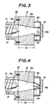
- An extruder 10 comprises a cylindrical barrel 12, a screw 14 arranged in the barrel, an extrusion head 16 disposed between an outlet 12a of the barrel and an extrusion die 18 and has substantially the same structure as in the conventional extruder except that an auxiliary extrusion head 20 is disposed between an extrusion head 16 and an extrusion die 18.
- the extrusion head 16 is provided at its interior with such a passageway 16a that the sectional shape of the passageway gradually changes from a circle located at the outlet 12a of the barrel 12 to an oblong rectangle having a width wider than that of a rubber sheet 26 to be formed.
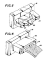
- the auxiliary extrusion head 20 disposed between the extrusion head 16 and the extrusion die 18 is provided with orientation controlling flow-paths 22, 24, 24 for changing the orientation through flowing of rubber, resin or the like to give an orientation distribution to the resulting rubber sheet.
- a squeezing flow-path 22 is arranged in a central portion of the auxiliary extrusion head 20 in the widthwise direction thereof, while a pair of spreading flow-paths 24, 24 are arranged on both sides of the flow-path 22.
- the flow-path 22 has a relationship of W1>W2 in which W1 is an inlet width and W2 is an outlet width
- each of the flow-paths 24, 24 has a relationship of W3 ⁇ W4 in which W3 is an inlet width and W4 is an outlet width.
- an end of an upper wall of the squeezing flow-path 22 is located at a position above an upper wall face of an outlet 18a or an opening portion of the extrusion die 18, while an end of a lower wall of the squeezing flow-path 22 is located at a position equal to or beneath a lower wall face of the opening portion 18a, whereby a barrier portion of the rubber composition to be extruded is formed in an outlet portion of the squeezing flow-path together with the extrusion die 18.
- ends of upper and lower walls of the spreading flow-path 24 are located at positions equal to upper and lower wall faces of the opening portion 18a of the extrusion die 18, whereby a non-barrier portion is formed in the outlet portion of the spreading flow-path 24.
- orientation of the rubber molecule or filler included in the rubber composition is controlled in the widthwise direction of the rubber sheet to be formed so as to have a desired orientation distribution.
- the orientation of the rubber molecule or filler is formed by stretching deformation of the high polymer material or the like during the flowing. For example, when rubber is suddenly flowed from a wider passageway to a narrower passageway, the flow rate is rapidly accelerated toward the narrow passageway and hence rubber is largely stretched in the flowing direction to orient the rubber molecule or filler in the extrusion direction. Therefore, when rubber is flowed through the auxiliary extrusion head 20, the rubber passing through the squeezing flow-path 22 is stretched in the extrusion direction because the width of the flow-path is narrowed toward the opening portion 18a and hence the rubber molecule or filler is oriented in the extrusion direction.
- a rubber sheet 26 for the formation of the tire tread is extruded by passing the rubber composition through the extruder 10, in which the rubber molecule or filler is oriented in the extrusion direction at the widthwise central region of the rubber sheet and is randomly oriented at both widthwise side regions thereof. That is, the orientation is changed at positions in the widthwise direction of the rubber sheet to provide a given orientation distribution.
- the rubber molecule or filler when the difference of W1>W2 in the squeezing flow-path 22 is made large, the rubber molecule or filler is more oriented in the extrusion direction, while when the difference of W3 ⁇ W4 in the spreading flow-path 24 is made larger, the rubber molecule or filler is more oriented in the widthwise direction and the orientation becomes random.
- a rubber sheet of about 200 mm in width is extruded through the conventional extruder shown in Fig. 1.
- Fig. 3 The dimensions in Fig.
- W1 160 mm
- W2 60 mm
- W3 30 mm
- W4 110 mm
- L 50 mm
- W0 200 mm
- the size of the opening portion 18a is the same as in the conventional extruder.
- a rubber composition used comprises 100 parts by weight of rubber (SBR), 100 parts by weight of carbon black, 100 parts by weight of an oil and given amounts of vulcanizing agent, vulcanization accelerator, accelerator activator, antioxidant and plasticizer and is used under the same conditions.
- a rubber sheet is formed by extruding the rubber composition through each of the above extruders and cured under the same conditions and then punched out in extrusion direction and widthwise direction to form DIN specimens, respectively. Thereafter, 300% tensile modulus of each of the specimens is measured according to a test method of JIS K6301. The measured results are shown in Table 1.
- the 300% tensile modulus in the extrusion direction is higher by about 20% than that in the widthwise direction irrespectively of the widthwise positions in the conventional extrusion method.
- the modulus in the extrusion direction is higher by about 30% than that in the widthwise direction at the central region, while the modulus in the extrusion direction is higher only by 6% than that in the widthwise direction at the side region, so that the resulting rubber sheet has an orientation distribution in the widthwise direction .
- the above embodiment uses the combination of squeezing flow-path and spreading flow-paths, there may be used various combinations of squeezing flow-path, spreading flow-path and straight flow-path as much as the given orientation distribution can be obtained in the widthwise direction of the rubber sheet. Furthermore, there may be used a combination of the squeezing flow-path satisfying a relationship of inlet height > outlet height and the spreading flow-path satisfying a relationship of inlet height ⁇ outlet height.
- high polymers such as thermoplastic resins and thermosetting resins may be used in addition to the above rubber reinforced with carbon black.
- a filler use may be made of inorganic and organic fillers such as calcium carbonate, basic magnesium carbonate hydrate, clay, silicates, natural silicic acid, alumina hydrate, barium sulfate, calcium sulfate, metal powder, wood powder, fruit shell powder, cellulose and the like.
- short fibers may be used as a filler and include cut pieces of organic fibers such as aromatic polyamide, vinylon, polyester, nylon, rayon and the like, needle crystal of cis-1,2-polybutadiene or the like, whisker of polyoxymethylene or the like, cut pieces of inorganic fibers such as glass, carbon, graphite, metal and the like, silicon carbide whisker, tungsten carbide whisker, alumina whisker and so on.
- organic fibers such as aromatic polyamide, vinylon, polyester, nylon, rayon and the like, needle crystal of cis-1,2-polybutadiene or the like, whisker of polyoxymethylene or the like, cut pieces of inorganic fibers such as glass, carbon, graphite, metal and the like, silicon carbide whisker, tungsten carbide whisker, alumina whisker and so on.
- fillers may be used alone or in admixture. Among them, all materials having an aspect ratio of less than 1 or more than 1 are oriented in any direction.
- the tread rubber is oriented in such a manner that when a ratio of 300% tensile modulus in the circumferential direction of the tire to 300% tensile modulus in the widthwise direction of the tire is a modulus ratio, the modulus ratio in the tread central region is 1.20 and the modulus ratio in the tread side region is 1.10.
- the tread rubber is oriented in such a manner that the modulus ratio in the tread central region is 1.30 and the modulus ratio in the tread side region is 1.10.
- the tread rubber is oriented in such a manner that the modulus ratio in the tread central region is 1.40 and the modulus ratio in the tread side region is 1.20.
- the tread rubber is oriented in such a manner that the modulus ratio in the tread central region is 1.45 and the modulus ratio in the tread side region is 1.15.
- the tread rubber is oriented in such a manner that the modulus ratio in both the tread central region and the tread side region is 1.00.
- This tire is the conventionally known tire.
- the running performance is evaluated by a feeling test of a driver on gripping force during the cornering when the test tire is mounted onto a rear wheel of a motorcycle and run on a test course and represented by an index value on the basis that Comparative Example 1 is 100.
- the wear resistance is evaluated by measuring an average remaining groove depth of the test tire after the test tire is run on the test course over a distance of 200 km after the evaluation of running performance and represented by an index value on the basis that Comparative Example 1 is 100. The larger the index value, the better the wear resistance.
- Table 2 Modulus ratio Running performance (index) Wear resistance (index) Tread side region Tread central region Example 1 1.10 1.20 119 108 Example 2 1.10 1.30 121 111 Example 3 1.20 1.40 116 113 Example 4 1.15 1.45 120 115 Comparative Example 1 1.00 1.00 100 100
- a pneumatic radial tire for passenger car having a tire size of 205/65R15 and having a tread comprised of a cap rubber layer and a base rubber layer, in which the modulus ratio of the base rubber layer is 1.09 in the tread central region corresponding to 0.6 times of a tread width and 0.91 in the tread side region.
- the shearing rigidity in the circumferential direction is increased in the tread central region considerably contributing to the braking performance, while the bending rigidity is lowered in the tread side region considerably contributing to the ride comfortability, so that the tire simultaneously satisfies both the braking performance and the ride comfortability.
Landscapes
- Engineering & Computer Science (AREA)
- Mechanical Engineering (AREA)
- Manufacturing & Machinery (AREA)
- Extrusion Moulding Of Plastics Or The Like (AREA)
Applications Claiming Priority (4)
| Application Number | Priority Date | Filing Date | Title |
|---|---|---|---|
| JP27322794A JP3343796B2 (ja) | 1994-11-08 | 1994-11-08 | 押出機及び材料の押出方法 |
| JP273227/94 | 1994-11-08 | ||
| JP32293394A JP3369768B2 (ja) | 1994-12-26 | 1994-12-26 | 配向性トレッドを備えた空気入りタイヤ |
| JP322933/94 | 1994-12-26 |
Publications (2)
| Publication Number | Publication Date |
|---|---|
| EP0711675A1 true EP0711675A1 (de) | 1996-05-15 |
| EP0711675B1 EP0711675B1 (de) | 1999-03-03 |
Family
ID=26550567
Family Applications (1)
| Application Number | Title | Priority Date | Filing Date |
|---|---|---|---|
| EP95307870A Expired - Lifetime EP0711675B1 (de) | 1994-11-08 | 1995-11-03 | Luftreifen mit Lauffläche aus einer orientierte Gummi |
Country Status (3)
| Country | Link |
|---|---|
| US (1) | US5702546A (de) |
| EP (1) | EP0711675B1 (de) |
| DE (1) | DE69508037T2 (de) |
Cited By (1)
| Publication number | Priority date | Publication date | Assignee | Title |
|---|---|---|---|---|
| FR3167330A1 (fr) * | 2024-10-15 | 2026-04-17 | Cabot Corporation | Procédés d’extrusion de compositions élastomères |
Families Citing this family (11)
| Publication number | Priority date | Publication date | Assignee | Title |
|---|---|---|---|---|
| US6106752A (en) * | 1996-09-24 | 2000-08-22 | The Goodyear Tire & Rubber Company | Use of injection molding to orient short fibers in desired directions |
| JP3390149B2 (ja) * | 1999-07-27 | 2003-03-24 | 住友ゴム工業株式会社 | スタッドレスタイヤ |
| EP1214183B1 (de) * | 1999-09-07 | 2003-05-21 | THE GOODYEAR TIRE & RUBBER COMPANY | Orientierung von kurzen fasern in einem kontinuierlichen verfahren |
| CA2324807A1 (en) * | 1999-11-05 | 2001-05-05 | Sumitomo Rubber Industries, Ltd. | Studless tire with radially directed short fibers |
| JP3308252B2 (ja) * | 1999-12-14 | 2002-07-29 | 住友ゴム工業株式会社 | 空気入りタイヤ |
| US7083436B2 (en) | 2001-03-06 | 2006-08-01 | International Business Machines Corporation | Particle distribution interposer and method of manufacture thereof |
| JP3678689B2 (ja) * | 2001-09-27 | 2005-08-03 | 住友ゴム工業株式会社 | ゴム組成物およびそれを用いたタイヤ |
| DE10341920B3 (de) * | 2003-09-11 | 2005-04-14 | Continental Aktiengesellschaft | Verfahren zur Herstellung eines Fahrzeugluftreifens |
| JP4263232B2 (ja) * | 2006-11-01 | 2009-05-13 | 横浜ゴム株式会社 | 高速耐久性能に優れる空気入りタイヤ |
| JP2008149990A (ja) * | 2006-12-20 | 2008-07-03 | Bridgestone Corp | 二輪車用空気入りタイヤ |
| US10710322B1 (en) * | 2015-06-12 | 2020-07-14 | Accredo Packaging, Inc | Matte film and method of manufacture therefore |
Citations (5)
| Publication number | Priority date | Publication date | Assignee | Title |
|---|---|---|---|---|
| FR2215331A1 (de) * | 1973-01-29 | 1974-08-23 | Kleber Colombes | |
| EP0106838A2 (de) * | 1982-10-20 | 1984-04-25 | Semperit Reifen Aktiengesellschaft | Fahrzeugluftreifen mit einer Radialkarkasse, wobei der Laufflächenteil aus einer der Achse näheren Basisschicht mit einer darüber angeordneten Kronenschicht besteht |
| GB2236504A (en) * | 1989-10-07 | 1991-04-10 | Liberato Mascia | Convergent-divergent dies to produce biaxial orientation in plastics products by extrusion or pultrusion |
| EP0468306A2 (de) * | 1990-07-12 | 1992-01-29 | Bando Chemical Industries, Limited | Verfahren zur Herstellung einer faserverstärkten elastischen Folie, Vorrichtung zu deren Herstellung und dabei zu verwendendes Werkzeug |
| EP0592218A1 (de) * | 1992-10-08 | 1994-04-13 | Sumitomo Rubber Industries Limited | Reifen |
Family Cites Families (11)
| Publication number | Priority date | Publication date | Assignee | Title |
|---|---|---|---|---|
| US3057389A (en) * | 1960-02-25 | 1962-10-09 | Firestone Tire & Rubber Co | High speed tire |
| GB1100135A (en) * | 1964-07-24 | 1968-01-24 | Dunlop Co Ltd | Pneumatic tyre |
| DE1480962A1 (de) * | 1965-12-21 | 1969-06-19 | Continental Gummi Werke Ag | Luftbereifung fuer Strassenfahrzeuge |
| US3945420A (en) * | 1970-08-05 | 1976-03-23 | Semperit Ag | Molded article formed of fiber reinforced material |
| US3907019A (en) * | 1970-09-30 | 1975-09-23 | Michelin & Cie | Tire treads made of an oriented elastomer mixture |
| JPS5850883B2 (ja) * | 1979-12-31 | 1983-11-12 | 東洋ゴム工業株式会社 | 少くとも2種類のゴムよりなるトレツドを有する空気入りタイヤ |
| JPS56146404A (en) * | 1980-04-14 | 1981-11-13 | Yokohama Rubber Co Ltd:The | Pneumatic tire |
| JPS57144109A (en) * | 1981-02-26 | 1982-09-06 | Sumitomo Rubber Ind Ltd | Radial tire |
| JPS61111804U (de) * | 1984-12-27 | 1986-07-15 | ||
| CA2049784A1 (en) * | 1990-08-30 | 1992-03-01 | Shingo Midorikawa | Studless pneumatic tire |
| US5526859A (en) * | 1992-12-14 | 1996-06-18 | Sumitomo Rubber Industries, Ltd. | Radial tires including short fibers |
-
1995
- 1995-11-03 DE DE69508037T patent/DE69508037T2/de not_active Expired - Lifetime
- 1995-11-03 EP EP95307870A patent/EP0711675B1/de not_active Expired - Lifetime
- 1995-11-08 US US08/555,326 patent/US5702546A/en not_active Expired - Lifetime
Patent Citations (5)
| Publication number | Priority date | Publication date | Assignee | Title |
|---|---|---|---|---|
| FR2215331A1 (de) * | 1973-01-29 | 1974-08-23 | Kleber Colombes | |
| EP0106838A2 (de) * | 1982-10-20 | 1984-04-25 | Semperit Reifen Aktiengesellschaft | Fahrzeugluftreifen mit einer Radialkarkasse, wobei der Laufflächenteil aus einer der Achse näheren Basisschicht mit einer darüber angeordneten Kronenschicht besteht |
| GB2236504A (en) * | 1989-10-07 | 1991-04-10 | Liberato Mascia | Convergent-divergent dies to produce biaxial orientation in plastics products by extrusion or pultrusion |
| EP0468306A2 (de) * | 1990-07-12 | 1992-01-29 | Bando Chemical Industries, Limited | Verfahren zur Herstellung einer faserverstärkten elastischen Folie, Vorrichtung zu deren Herstellung und dabei zu verwendendes Werkzeug |
| EP0592218A1 (de) * | 1992-10-08 | 1994-04-13 | Sumitomo Rubber Industries Limited | Reifen |
Cited By (1)
| Publication number | Priority date | Publication date | Assignee | Title |
|---|---|---|---|---|
| FR3167330A1 (fr) * | 2024-10-15 | 2026-04-17 | Cabot Corporation | Procédés d’extrusion de compositions élastomères |
Also Published As
| Publication number | Publication date |
|---|---|
| DE69508037D1 (de) | 1999-04-08 |
| EP0711675B1 (de) | 1999-03-03 |
| DE69508037T2 (de) | 1999-09-16 |
| US5702546A (en) | 1997-12-30 |
Similar Documents
| Publication | Publication Date | Title |
|---|---|---|
| US4057610A (en) | Hose reinforced with discontinuous fibers oriented in the radial direction | |
| EP1677996B1 (de) | Hochleistungsreifen für kraftfahrzeugräder | |
| EP0711675B1 (de) | Luftreifen mit Lauffläche aus einer orientierte Gummi | |
| EP3348422A1 (de) | Personenkraftwagenluftreifen | |
| US6427738B1 (en) | Tire and vulcanized rubber including elongated cells | |
| EP3348423A1 (de) | Luftreifen | |
| EP1241026B1 (de) | Reifen | |
| DE69825669T2 (de) | Luftreifen | |
| EP2366559B1 (de) | Reifen mit Lauffläche mit weicherer innerer Übergangsgummischicht kurzer Faserverstärkung | |
| EP1452342B1 (de) | Luftreifen | |
| JPH01153305A (ja) | ラジアルタイヤ | |
| DE102006015000A1 (de) | Reifen, insbesondere Lastwagenrennreifen | |
| EP1142695A2 (de) | Verfahren zum Herstellen von Fahrzeugreifen | |
| CN114981096B (zh) | 摩托车轮胎 | |
| AU671856B2 (en) | Tires | |
| DE112013007330B4 (de) | Luftreifen für Personenkraftwagen | |
| DE112015002374T5 (de) | Luftreifen | |
| JP3437298B2 (ja) | 空気入りタイヤ | |
| JPS6060010A (ja) | 空気入りタイヤ | |
| JPH1120408A (ja) | 空気入りタイヤ | |
| JP4256024B2 (ja) | 空気入りタイヤ | |
| DE112021002763B4 (de) | Kautschukzusammensetzung für Reifen sowie Reifen enthaltend die Kautschukzusammensetzung | |
| JP3061356B2 (ja) | 空気入りタイヤの製造方法 | |
| DE102010037065B4 (de) | Fahrzeugluftreifen mit Seitenwand-Verstärkungsprofil | |
| CA1041921A (en) | Hose reinforced with discontinuous fibers oriented in the radial direction |
Legal Events
| Date | Code | Title | Description |
|---|---|---|---|
| PUAI | Public reference made under article 153(3) epc to a published international application that has entered the european phase |
Free format text: ORIGINAL CODE: 0009012 |
|
| AK | Designated contracting states |
Kind code of ref document: A1 Designated state(s): DE FR GB IT |
|
| 17P | Request for examination filed |
Effective date: 19960920 |
|
| GRAG | Despatch of communication of intention to grant |
Free format text: ORIGINAL CODE: EPIDOS AGRA |
|
| 17Q | First examination report despatched |
Effective date: 19980213 |
|
| GRAG | Despatch of communication of intention to grant |
Free format text: ORIGINAL CODE: EPIDOS AGRA |
|
| GRAG | Despatch of communication of intention to grant |
Free format text: ORIGINAL CODE: EPIDOS AGRA |
|
| GRAH | Despatch of communication of intention to grant a patent |
Free format text: ORIGINAL CODE: EPIDOS IGRA |
|
| GRAH | Despatch of communication of intention to grant a patent |
Free format text: ORIGINAL CODE: EPIDOS IGRA |
|
| GRAA | (expected) grant |
Free format text: ORIGINAL CODE: 0009210 |
|
| AK | Designated contracting states |
Kind code of ref document: B1 Designated state(s): DE FR GB IT |
|
| REF | Corresponds to: |
Ref document number: 69508037 Country of ref document: DE Date of ref document: 19990408 |
|
| ITF | It: translation for a ep patent filed | ||
| ET | Fr: translation filed | ||
| PLBE | No opposition filed within time limit |
Free format text: ORIGINAL CODE: 0009261 |
|
| STAA | Information on the status of an ep patent application or granted ep patent |
Free format text: STATUS: NO OPPOSITION FILED WITHIN TIME LIMIT |
|
| 26N | No opposition filed | ||
| REG | Reference to a national code |
Ref country code: GB Ref legal event code: IF02 |
|
| PGFP | Annual fee paid to national office [announced via postgrant information from national office to epo] |
Ref country code: DE Payment date: 20101027 Year of fee payment: 16 |
|
| REG | Reference to a national code |
Ref country code: DE Ref legal event code: R119 Ref document number: 69508037 Country of ref document: DE Effective date: 20130601 |
|
| PG25 | Lapsed in a contracting state [announced via postgrant information from national office to epo] |
Ref country code: DE Free format text: LAPSE BECAUSE OF NON-PAYMENT OF DUE FEES Effective date: 20130601 |
|
| REG | Reference to a national code |
Ref country code: FR Ref legal event code: CA Effective date: 20140812 |
|
| PGFP | Annual fee paid to national office [announced via postgrant information from national office to epo] |
Ref country code: GB Payment date: 20141119 Year of fee payment: 20 Ref country code: FR Payment date: 20141119 Year of fee payment: 20 |
|
| PGFP | Annual fee paid to national office [announced via postgrant information from national office to epo] |
Ref country code: IT Payment date: 20141125 Year of fee payment: 20 |
|
| REG | Reference to a national code |
Ref country code: GB Ref legal event code: PE20 Expiry date: 20151102 |
|
| PG25 | Lapsed in a contracting state [announced via postgrant information from national office to epo] |
Ref country code: GB Free format text: LAPSE BECAUSE OF EXPIRATION OF PROTECTION Effective date: 20151102 |