EP0711705A2 - Verfahren und Vorrichtung zum Einhüllen von Tampons - Google Patents
Verfahren und Vorrichtung zum Einhüllen von Tampons Download PDFInfo
- Publication number
- EP0711705A2 EP0711705A2 EP95116663A EP95116663A EP0711705A2 EP 0711705 A2 EP0711705 A2 EP 0711705A2 EP 95116663 A EP95116663 A EP 95116663A EP 95116663 A EP95116663 A EP 95116663A EP 0711705 A2 EP0711705 A2 EP 0711705A2
- Authority
- EP
- European Patent Office
- Prior art keywords
- carrier
- carriers
- tampons
- tampon
- tube
- Prior art date
- Legal status (The legal status is an assumption and is not a legal conclusion. Google has not performed a legal analysis and makes no representation as to the accuracy of the status listed.)
- Withdrawn
Links
- 238000000034 method Methods 0.000 title claims description 40
- 239000000969 carrier Substances 0.000 claims abstract description 95
- 230000004044 response Effects 0.000 claims abstract description 10
- 239000000463 material Substances 0.000 claims description 21
- 238000010438 heat treatment Methods 0.000 claims description 7
- 230000005484 gravity Effects 0.000 claims description 6
- 238000000926 separation method Methods 0.000 claims description 5
- 229920000298 Cellophane Polymers 0.000 claims description 4
- 230000009471 action Effects 0.000 claims description 4
- 239000004743 Polypropylene Substances 0.000 claims description 3
- 230000000694 effects Effects 0.000 claims description 3
- -1 polypropylene Polymers 0.000 claims description 3
- 229920001155 polypropylene Polymers 0.000 claims description 3
- 238000011144 upstream manufacturing Methods 0.000 claims description 2
- 238000007789 sealing Methods 0.000 description 14
- 230000009467 reduction Effects 0.000 description 7
- 210000005069 ears Anatomy 0.000 description 6
- 230000008030 elimination Effects 0.000 description 6
- 238000003379 elimination reaction Methods 0.000 description 6
- 230000008901 benefit Effects 0.000 description 4
- 238000007493 shaping process Methods 0.000 description 4
- 238000010276 construction Methods 0.000 description 3
- 238000010409 ironing Methods 0.000 description 3
- 238000003491 array Methods 0.000 description 2
- 230000015572 biosynthetic process Effects 0.000 description 2
- 235000013336 milk Nutrition 0.000 description 2
- 239000008267 milk Substances 0.000 description 2
- 210000004080 milk Anatomy 0.000 description 2
- 230000006978 adaptation Effects 0.000 description 1
- 238000004458 analytical method Methods 0.000 description 1
- 235000013361 beverage Nutrition 0.000 description 1
- 230000008859 change Effects 0.000 description 1
- 230000000295 complement effect Effects 0.000 description 1
- 239000000470 constituent Substances 0.000 description 1
- 238000011109 contamination Methods 0.000 description 1
- 238000007796 conventional method Methods 0.000 description 1
- 238000001816 cooling Methods 0.000 description 1
- 238000005520 cutting process Methods 0.000 description 1
- 230000007547 defect Effects 0.000 description 1
- 230000001747 exhibiting effect Effects 0.000 description 1
- 238000000605 extraction Methods 0.000 description 1
- 235000011389 fruit/vegetable juice Nutrition 0.000 description 1
- 238000003780 insertion Methods 0.000 description 1
- 230000037431 insertion Effects 0.000 description 1
- 238000007689 inspection Methods 0.000 description 1
- 239000007788 liquid Substances 0.000 description 1
- 238000004519 manufacturing process Methods 0.000 description 1
- 230000008569 process Effects 0.000 description 1
- 238000003860 storage Methods 0.000 description 1
- 230000032258 transport Effects 0.000 description 1
Images

Classifications
-
- A—HUMAN NECESSITIES
- A61—MEDICAL OR VETERINARY SCIENCE; HYGIENE
- A61F—FILTERS IMPLANTABLE INTO BLOOD VESSELS; PROSTHESES; DEVICES PROVIDING PATENCY TO, OR PREVENTING COLLAPSING OF, TUBULAR STRUCTURES OF THE BODY, e.g. STENTS; ORTHOPAEDIC, NURSING OR CONTRACEPTIVE DEVICES; FOMENTATION; TREATMENT OR PROTECTION OF EYES OR EARS; BANDAGES, DRESSINGS OR ABSORBENT PADS; FIRST-AID KITS
- A61F13/00—Bandages or dressings; Absorbent pads
- A61F13/15—Absorbent pads, e.g. sanitary towels, swabs or tampons for external or internal application to the body; Supporting or fastening means therefor; Tampon applicators
- A61F13/20—Tampons, e.g. catamenial tampons; Accessories therefor
- A61F13/2051—Tampons, e.g. catamenial tampons; Accessories therefor characterised by the material or the structure of the inner absorbing core
-
- A—HUMAN NECESSITIES
- A61—MEDICAL OR VETERINARY SCIENCE; HYGIENE
- A61F—FILTERS IMPLANTABLE INTO BLOOD VESSELS; PROSTHESES; DEVICES PROVIDING PATENCY TO, OR PREVENTING COLLAPSING OF, TUBULAR STRUCTURES OF THE BODY, e.g. STENTS; ORTHOPAEDIC, NURSING OR CONTRACEPTIVE DEVICES; FOMENTATION; TREATMENT OR PROTECTION OF EYES OR EARS; BANDAGES, DRESSINGS OR ABSORBENT PADS; FIRST-AID KITS
- A61F13/00—Bandages or dressings; Absorbent pads
- A61F13/15—Absorbent pads, e.g. sanitary towels, swabs or tampons for external or internal application to the body; Supporting or fastening means therefor; Tampon applicators
- A61F13/20—Tampons, e.g. catamenial tampons; Accessories therefor
- A61F13/2082—Apparatus or processes of manufacturing
- A61F13/2085—Catamenial tampons
-
- B—PERFORMING OPERATIONS; TRANSPORTING
- B29—WORKING OF PLASTICS; WORKING OF SUBSTANCES IN A PLASTIC STATE IN GENERAL
- B29C—SHAPING OR JOINING OF PLASTICS; SHAPING OF MATERIAL IN A PLASTIC STATE, NOT OTHERWISE PROVIDED FOR; AFTER-TREATMENT OF THE SHAPED PRODUCTS, e.g. REPAIRING
- B29C65/00—Joining or sealing of preformed parts, e.g. welding of plastics materials; Apparatus therefor
- B29C65/02—Joining or sealing of preformed parts, e.g. welding of plastics materials; Apparatus therefor by heating, with or without pressure
-
- B—PERFORMING OPERATIONS; TRANSPORTING
- B29—WORKING OF PLASTICS; WORKING OF SUBSTANCES IN A PLASTIC STATE IN GENERAL
- B29C—SHAPING OR JOINING OF PLASTICS; SHAPING OF MATERIAL IN A PLASTIC STATE, NOT OTHERWISE PROVIDED FOR; AFTER-TREATMENT OF THE SHAPED PRODUCTS, e.g. REPAIRING
- B29C66/00—General aspects of processes or apparatus for joining preformed parts
- B29C66/01—General aspects dealing with the joint area or with the area to be joined
- B29C66/05—Particular design of joint configurations
- B29C66/10—Particular design of joint configurations particular design of the joint cross-sections
- B29C66/11—Joint cross-sections comprising a single joint-segment, i.e. one of the parts to be joined comprising a single joint-segment in the joint cross-section
- B29C66/112—Single lapped joints
- B29C66/1122—Single lap to lap joints, i.e. overlap joints
-
- B—PERFORMING OPERATIONS; TRANSPORTING
- B29—WORKING OF PLASTICS; WORKING OF SUBSTANCES IN A PLASTIC STATE IN GENERAL
- B29C—SHAPING OR JOINING OF PLASTICS; SHAPING OF MATERIAL IN A PLASTIC STATE, NOT OTHERWISE PROVIDED FOR; AFTER-TREATMENT OF THE SHAPED PRODUCTS, e.g. REPAIRING
- B29C66/00—General aspects of processes or apparatus for joining preformed parts
- B29C66/01—General aspects dealing with the joint area or with the area to be joined
- B29C66/05—Particular design of joint configurations
- B29C66/20—Particular design of joint configurations particular design of the joint lines, e.g. of the weld lines
- B29C66/21—Particular design of joint configurations particular design of the joint lines, e.g. of the weld lines said joint lines being formed by a single dot or dash or by several dots or dashes, i.e. spot joining or spot welding
-
- B—PERFORMING OPERATIONS; TRANSPORTING
- B29—WORKING OF PLASTICS; WORKING OF SUBSTANCES IN A PLASTIC STATE IN GENERAL
- B29C—SHAPING OR JOINING OF PLASTICS; SHAPING OF MATERIAL IN A PLASTIC STATE, NOT OTHERWISE PROVIDED FOR; AFTER-TREATMENT OF THE SHAPED PRODUCTS, e.g. REPAIRING
- B29C66/00—General aspects of processes or apparatus for joining preformed parts
- B29C66/40—General aspects of joining substantially flat articles, e.g. plates, sheets or web-like materials; Making flat seams in tubular or hollow articles; Joining single elements to substantially flat surfaces
- B29C66/41—Joining substantially flat articles ; Making flat seams in tubular or hollow articles
- B29C66/43—Joining a relatively small portion of the surface of said articles
- B29C66/431—Joining the articles to themselves
- B29C66/4312—Joining the articles to themselves for making flat seams in tubular or hollow articles, e.g. transversal seams
- B29C66/43121—Closing the ends of tubular or hollow single articles, e.g. closing the ends of bags
-
- B—PERFORMING OPERATIONS; TRANSPORTING
- B29—WORKING OF PLASTICS; WORKING OF SUBSTANCES IN A PLASTIC STATE IN GENERAL
- B29C—SHAPING OR JOINING OF PLASTICS; SHAPING OF MATERIAL IN A PLASTIC STATE, NOT OTHERWISE PROVIDED FOR; AFTER-TREATMENT OF THE SHAPED PRODUCTS, e.g. REPAIRING
- B29C66/00—General aspects of processes or apparatus for joining preformed parts
- B29C66/70—General aspects of processes or apparatus for joining preformed parts characterised by the composition, physical properties or the structure of the material of the parts to be joined; Joining with non-plastics material
- B29C66/71—General aspects of processes or apparatus for joining preformed parts characterised by the composition, physical properties or the structure of the material of the parts to be joined; Joining with non-plastics material characterised by the composition of the plastics material of the parts to be joined
Definitions
- the present invention relates to articles of feminine hygiene known as tampons, and more particularly to improvements in so-called digital tampons which are insertable directly by hand and, as a rule, are provided with strings serving to facilitate manual extraction of tampons from body cavities.
- a digital tampon normally resembles an elongated bullet-shaped cylinder having a rounded leading end and a trailing end or another part attached to one end of a string the other end of which is accessible at the exterior of the inlet to the body cavity which receives the tampon.
- Each tampon is confined in a tubular envelope which is or which can be made of a light-transmitting material and is closed at both ends.
- An intermediate portion of the envelope is or can be provided with a tear strip which facilitates access to the tampon preparatory to introduction into a body cavity.
- the string is stored in the envelope in folded condition adjacent the trailing end of the tampon.
- Attempts to facilitate predictable folding of strings at the trailing ends of the tampons prior to closing of both ends of the respective tubular envelopes include the introduction of tampons and of the respective strings into tubular carriers and circulation of air in the carriers for the purpose of influencing the folding of the strings, i.e., the ultimate shape and positioning of the string within the confines of a closed tubular envelope at the trailing end of the respective tampon.
- the utilization of currents of air contributes significantly to the complexity and cost of heretofore known apparatus which are designed to confine tampons and their strings in tubular envelopes.
- the utilization of air currents does not ensure predictable folding of the strings; as a rule, the folded portions of a string extend randomly in part across and in part along short arcuate paths at the trailing ends of the respective tampons.
- Still another drawback of heretofore known methods of and apparatus for confining digital tampons in tubular envelopes is that the closed ends of the envelopes at the trailing ends of the confined tampons are not adequately sealed.
- such sealing is effected by advancing the closed ends of envelopes at the trailing ends of the confined tampons along a heated surface which is supposed to establish a bond between the overlapping or partially overlapping panels at the respective closed ends of the envelopes.
- Such treatment does not ensure reliable bonding of the partially or fully overlapping panels to each other.
- the advancement of tubular envelopes along a heated surface is likely to intensify the formation of the aforediscussed undesirable corner portions or "ears".
- An additional drawback of conventional methods of and apparatus for confining digital tampons in tubular envelopes is that the desirable recesses at the trailing ends of the tampons are likely to disappear or that their depth is reduced and/or that their shape is altered during storage of confined tampons. Such recesses are desirable for convenient application of the tip of an index finger or another finger during introduction of an unsealed tampon into a body cavity.
- the aforediscussed advancement of closed ends of tubular envelopes adjacent the trailing ends of confined tampons is likely to contribute to a reduction of the depth of recesses in the trailing ends of the tampons.
- the condensed material of a confined tampon tends to expand in the interior of its envelope.
- a finished envelope does not or is not likely to yield in a radial direction; however, it does not interfere with an expansion of the tampon in a direction to reduce the depth of the recess in its trailing end.
- An object of the invention is to provide a novel and improved method of confining digital tampons in tubular envelopes (hereinafter called tubes for short).
- Another object of the invention is to provide a method which renders it possible to impart a desired configuration to the trailing ends of confined tampons, to the strings which are affixed to the trailing ends of the tampons as well as to the adjacent closed ends of the tubes.
- a further object of the invention is to provide a novel and improved method of shaping the ends of tubes adjacent the trailing ends of the confined tampons.
- An additional object of the invention is to provide a novel and improved method of eliminating, or at least reducing the prominence, of corner portions or "ears" at the closed ends of tubes adjacent the trailing ends of confined tampons.
- Still another object of the invention is to provide a method which renders it possible to close the ends of tubes in a highly predictable manner so that the dimensions as well as the configuration of each of a short or long series of successively closed and sealed tubes match a desirable optimum size and/or shape.
- a further object of the invention is to provide a method which renders it possible to select the configuration as well as the dimensions of each of a short or long series of successively confined tampons in such a way that the confined tampons can be readily collated and packaged in a simple and time saving manner.
- Another object of the invention is to provide novel and improved combinations of digital tampons, strings and tubes which are obtained in accordance with the above outlined method.
- An additional object of the invention is to provide a novel and improved mode of predictably collapsing or folding strings which are connected with the trailing ends of digital tampons.
- Still another object of the invention is to provide a method of imparting to the trailing ends of confined tampons an optimum configuration as a consequence of making and closing the tubes for confinement of the tampons.
- a further object of the invention is to provide a method which renders it possible to simultaneously influence the making, closing and sealing of tubes, predictable collapsing or folding of the strings, and predictable shaping of the trailing ends of digital tampons.
- Another object of the invention is to provide a novel and improved apparatus for the practice of the above outlined method.
- An additional object of the invention is to provide the apparatus with novel and improved means for sealing and shaping those ends of the tubes which are adjacent the trailing ends of the confined tampons.
- Still another object of the invention is to provide the apparatus with novel and improved means for influencing the configuration of the trailing ends of confined digital tampons simultaneously with predictable and reliable sealing of the adjacent end portions of the respective tubes.
- a further object of the invention is to provide a simple, compact and reliable apparatus for the mass production of confined digital tampons at a rate greatly exceeding the outputs of heretofore known apparatus.
- Another object of the invention is to provide the apparatus with novel and improved means for eliminating or at least reducing the dimensions of the aforediscussed corner portions or "ears" at the closed ends of tubes adjacent the trailing ends of the confined tampons.
- An additional object of the invention is to provide the above outlined apparatus with means for ensuring predictable and optimal folding or collapsing of strings which are or which can be attached to the trailing ends of digital tampons.
- Still another object of the invention is to provide an apparatus which can turn out confined digital tampons of such size and shape that the tampons can be readily collated and packaged and that the tampons can be readily manipulated by ultimate users for the purpose of removing their tubular envelopes as well as for the purpose of inserting them into body cavities.
- One feature of the present invention resides in the provision of a method of confining an elongated substantially cylindrical tampon.
- the method comprises the steps of introducing the tampon into a tubular carrier, surrounding at least a portion of the carrier by a blank of flexible sheet material and converting the blank into a tube having a first open end remote from and a second open end extending beyond an open end of the carrier, closing the second end of the tube including providing the second end with a plurality of at least partially overlapping panels which are disposed at least close to a plane at least substantially normal to a longitudinal axis of the carrier and which, as a rule, define at least one corner portion projecting substantially radially of and away from the axis of the carrier and beyond an external surface of a portion of the tube adjacent the aforementioned plane, and deforming the closed end of the tube including at least reducing the extent to which the at least one corner portion projects beyond the external surface.
- the sheet material of the blank is preferably deformable (or more readily deformable) in response to the application of heat, and the deforming step can include heating the closed end of the tube.
- the material of the blank i.e., the material of the tube
- the material of the tube can be selected from the group including cellophane and polypropylene.
- the deforming step can include providing the outer surface of the closed end of the tube with a recess, preferably with a recess the making of which involves the making of a similar recess in one end of the confined tampon.
- the method further comprises the step of expelling the tampon through the open end of the carrier with attendant separation of the tube from the carrier (namely stripping of the tube off the carrier) as a result of impingement of the tampon upon the closed and deformed end of the tube.
- expelling step is normally followed by the step of closing the first end of the tube, e.g., in a manner similar to closing the upper ends of cardboard containers for milk or other liquids.
- the expelling step can include advancing in the carrier a pusher against the tampon and in a direction to move the tampon through and beyond the open end of the carrier.
- the method further comprises the step of advancing the carrier substantially at right angles to its longitudinal axis in the course of at least one of the introducing, surrounding, closing, deforming and sealing steps.
- the introducing step can include positioning the tampon in the carrier at a location at least slightly spaced apart from the open end of the carrier, and such method preferably further includes the step of shifting the tampon relative to the carrier toward the closed end of the tube not later than in the course of the deforming step.
- a tampon of the type to be confined in accordance with the above outlined method is provided with an elongated string having a first end which is carried by the tampon and a second end which is remote from the trailing end of the tampon when the string is under tension.
- the method of confining tampons which are provided with strings preferably further comprises the step of maintaining the carrier in an at least substantially upright position so that the open end of the carrier is located below the other end.
- the introducing step then includes causing the string and thereupon the tampon to enter the carrier through the other end of the carrier so that the string depends from the tampon under the action of gravity, and such method further comprises the step of shifting the tampon in the carrier toward the closed end of the tube prior to the deforming step whereby the string curls above and along the closed end of the tube adjacent the open end of the carrier.
- the deforming step of such method preferably includes displacing a substantially central portion of the closed end of the tube toward the trailing end of the tampon in the carrier so that the displaced central portion of the closed end is at least partially surrounded by the coiled string.
- the deforming step can include only the provision of a recess in the exposed outer surface of the closed end of the tube.
- such deforming step can also include imparting an at least substantially circular shape to a portion of the closed end which surrounds the recess. This automatically entails the elimination (or at least a considerable reduction of the prominence) of the aforediscussed corner portion or portions.
- the apparatus comprises means (e.g., an endless chain) for advancing a series of successive open-ended tubular carriers along a predetermined path, means for introducing tampons into successive carriers in a first portion of the path, means for draping blanks of flexible sheet material around successive carriers in a second portion of the path including means for converting the blanks into open-ended tubes each having a first open end remote from and a second open end extending beyond an open end of the respective carrier, means for closing the second open ends of tubes surrounding the respective carriers in a third portion of the path including means for providing each closed end with a plurality of at least partially overlapping panels each of which is disposed at least close to a plane at least substantially normal to a longitudinal axis of the respective carrier and which define at least one corner portion projecting substantially radially of and away from the respective axis and beyond an external surface of a portion of the tube adjacent the aforementioned plane
- the apparatus further comprises means for expelling the tampons from successive carriers in a fifth portion of the path including means for displacing the tampons through and beyond the open ends of the respective carriers so that the tampons strip the corresponding tubes off their carriers.
- the deforming means can include profiled heating means serving to contact the closed ends of tubes surrounding the respective carriers in the fourth portion of the path.
- the profiled heating means can include at least one tool having a surface confronting the closed end of a tube in the fourth portion of the path, and means for effecting a movement of the at least one tool toward a tube and/or of a tube toward the at least one tool in the fourth portion of the path in order to effect an exchange of heat between the surface of the at least one tool and the confronting closed end of the tube.
- the surface of the at least one tool can be provided with a protuberance (e.g., a substantially conical or hemispherical protuberance) which is engageable with a central portion of the closed end of a tube in the fourth portion of the path, or with a protuberance and a recess which surrounds the protuberance and is bounded by a surface serving to eliminate or to at least reduce the prominency or size of the aforementioned edge portion or edge portions defined by the panels of the closed ends of the tubes.
- a protuberance e.g., a substantially conical or hemispherical protuberance
- the advancing means preferably includes means for maintaining each carrier in an at least substantially upright position so that the open end of each carrier is located below the tampon in the respective carrier.
- the introducing means of such apparatus preferably includes means for causing each string and thereupon the corresponding tampon to enter through an open upper end of the respective carrier so that the string depends from the corresponding tampon by gravity, and such apparatus preferably further comprises means for shifting the tampons in the respective carriers downwardly toward the closed ends of the respective tubes not later than in the fourth portion of the path whereby the strings automatically curl along the upper sides of closed ends of the respective tubes adjacent the open lower ends of the respective carriers.
- the deforming means can include means for displacing a substantially central portion of the closed end of a tube in the fourth portion of the path toward the trailing end of the respective tampon so that the displaced substantially central portion is at least partially surrounded by the respective coiled string.
- the aforementioned shifting means can form part of the aforementioned expelling means or vice versa.
- the advancing means can include means for moving successive carriers of the series sideways in a predetermined direction, and the first portion of the path is preferably located upstream of the second portion of the path, as seen in the predetermined direction.
- the expelling means can be designed to expel the tampons from the respective carriers of the series from the fifth portion of the predetermined path into a second path, and such apparatus preferably further comprises means for closing the open first ends of the tubes in the second path.
- the deforming means can merely include or constitute means for providing the outer surface of each closed end with a recess. However, it is presently preferred to employ deforming means which further includes means for imparting a substantially circular shape to that portion of each closed end which surrounds the respective recess. This entails an automatic elimination or at least a pronounced reduction of the size of the corner portions.
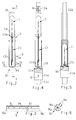
- FIG. 1 there are shown all relevant parts of an apparatus which embodies one form of the present invention and is utilized to confine elongated substantially cylindrical (bullet-shaped) digital tampons 1 (FIGS. 2, 4 and 5) in tubes 9 (FIGS. 2 to 6) which can be made of a light-transmitting material such as polypropylene, cellophane or other suitable sheet material.
- the tube 9 of FIG. 3 is provided with a tear strip 9i which enables the user to gain access to the tampon 1 and to an elongated string 13 (FIGS.
- one end (13a) of which is carried by (e.g., affixed to the adjacent trailing end 1a of) the respective tampon 1 and the other end (13b) of which is remote from the tampon when the string 13 is tensioned by gravity (as shown in FIGS. 2 and 4) or when the end 13b is pulled by the fingers of a person desiring to extract the tampon 1 from a body cavity.
- Each tube 9 constitutes a converted blank 7 (FIG. 1) which was severed from a web (coming from a bobbin) and is draped around one of a series of successive elongated tubular (preferably cylindrical) carriers 3 which are advanced along an elongated path in the idrection of arrow F by an endless chain or belt 2 in such positions that the central longitudinal axes Y-Y of the carriers 3 are at least substantially vertical, that the carriers 3 advanced by the belt or chain 2 are equidistant from each other (as seen in the direction of the arrow F), and that the open upper ends 3b of successive carriers are accessible at a first portion A of their endless path for introduction of discrete digital tampons 1 each of which is already connected with a string 13.
- the means for introducing discrete digital tampons 1 into successive carriers 3 on the belt or chain 2 includes an endless flexible belt or chain 5 which delivers a series of suitably spaced apart tampons (with strings 13 already depending from their trailing ends 1a) from a so-called knotting drum to the portion A of the path for the carriers 3.
- the belt or chain 5 also transports a series of carriers (not specifically shown) in the form of upright cylinders or the like each of which contains a tampon 1 and a string 13.
- each carrier 3 which advances in the direction of the arrow F beyond the transfer drum 5 of the introducing means 4, 5 contains an upright tampon 1 and a string 13 having its upper end 13a affixed e.g. to the trailing (lower) end 1a of the tampon and its lower end 13b spaced apart from the trailing end 1a.
- Such string assumes the position shown in FIGS. 2 and 4 under the action of gravity.
- FIG. 3 A finished tube 9 is shown in FIG. 3.
- such tube is or can be provided with a tear strip 9i (tear strips are preferably provided on the running web or webs which are converted into successive blanks 7 consisting of cellophane or any other suitable sheet material).
- FIG. 9i tear strips are preferably provided on the running web or webs which are converted into successive blanks 7 consisting of cellophane or any other suitable sheet material).
- FIG. 1 merely shows two so-called metering or cutting devices 6b, two forming drums 6a and two so-called side tagging devices 8, 14. Successive blanks 7 are converted into tubes 9 during advancement of the respective carriers 3 along the first or upper forming drum 6a of the unit 6 (as viewed in FIG.
- the side tagging device 8 provides the overlapping marginal portions of successive open-ended tubes 9 with longitudinally spaced apart bonds 9j (which can be said to constitute spot welds) to ensure that the originally substantially trough-shaped partially deformed blanks 7 cannot open up (i.e., reassume a substantially trough-shaped configuration) on their way (with the respective carriers 3) from the first or upper transfer drum 6a toward the lower or second transfer drum 6a of the unit 6 shown in FIG. 1.
- the tagging device 14 provides the marginal portions of successive open-ended tubes 9 with longitudinally extending axially parallel seams 9k (FIG.
- the tagging devices 8 and 14 are or can be heated if the sheet material of the blanks 7 and tubes 9 is such that overlapping portions of the tubes 9 can be readily bonded to each other in response to the application of heat.
- the unit 6 can comprise a so-called side sealing drum 6e which follows the second or lower transfer drum 6a and provides the overlapping marginal portions of successive tubes 9 with axially parallel seams 9k each of which extends or can extend all the way from the open end 9a to the open end 9b of the respective envelope or tube 9.
- the side sealing drum 6e of the unit 6 shown in FIG. 1 is followed by means for closing the open lower ends 9b of successive tubes 9 in a plane (shown in FIG. 2 as a horizontal or substantially horizontal plane X-X) which is at least substantially perpendicular to the longitudinal axes Y-Y of the continuously advancing carriers 3.
- the closing means includes a so-called bottom folding drum 10 and a bottom ironing section 10a which follows the drum 10 and is located in a third portion C of the path for advancement of tampons 1 with the carriers 3.
- a closed end 9b of a tube 9 is shown (at 9c) in each of FIGS. 2 and 4-6.
- Such closed end 9c includes a plurality of at least partially overlapping panels 9d which define one or more relatively sharp corner portions or "ears" 9e (FIG. 6) which, in the absence of any undertakings to the contrary, would detract from the appearance of the wrapped and sealed digital tampons and would even be likely to scratch the hand or hands of a user desiring to gain access to the tampon 1 and the corresponding string 13.
- Such user must at least partially remove the tear strip 9i of the respective closed and sealed tube 9.
- the action of the bottom ironing section 10a is likely to increase the pronouncedness or prominence of the corner portion or portions 9e, i.e., such corner portion or portions are even more likely to extend radially of the axes Y-Y of the respective carriers 3 and beyond the external surfaces 9f (FIG. 2) of those cylindrical or substantially cylindrical portions of the tubes 9 which are immediately adjacent the closed ends 9c.
- the bottom ironing section 10a can be replaced by or is used jointly with novel and improved means ll for deforming the closed bottom ends 9c of successive tubes 9 while such tubes advance along a fourth portion D of the path for tampons 1 with the respective carriers 3.
- the sealing means 11 comprises a drum 11f which carries a set of equidistant vertically movable combined heating and deforming tools 11a (FIGS. 4 and 5) each of which is located below and is in axial alignment with one of the carriers 3 advancing with their chain or belt 2 along the periphery of the drum 11f.
- Each tool 11a has a profiled surface 11b provided with a centrally located upwardly extending protuberance 11d and an annular recess 11e surrounding the respective protuberance 11d.
- the means for effecting relative axial movements between the carriers 3 and the respective tools 11a includes vertical shafts 11c which support the tools 11a and are moved up and down during sidewise movement with and along the periphery of the combined bottom sealing and deforming or contouring drum 11f.
- the tools 11a can be raised (arrow G in FIG. 4) and lowered by being provided with followers extending into the groove of a suitable cam installed beneath the path for the shafts 11c for the tools 11a. Such followers are or can be provided on the shafts 11c.
- the drum 11f of the deforming means 11 further carries a set of pushers 12a (FIGS. 4 and 5) which serve as a means for shifting the tampons 1 in the respective carriers 3 in a downward direction (arrow H in FIG. 4) in order to effect automatic coiling of the strings 13 along the marginal portions of the upper sides of the closed ends 9c of the respective tubes 9 (compare FIGS. 4 and 5).
- the pushers 12a serve as a means for maintaining the respective tampons 1 in predetermined positions relative to the corresponding carriers 3, namely at selected distances from the open lower ends 3a and the upper ends 3b of such carriers (see FIG. 5). This ensures that the surfaces 11b of the respective heated tools 11a can influence the configuration of the respective closed ends 9c as well as the configuration of the undersides of trailing ends 1a of the respective tampons 1.
- the protuberances 11d provide the undersides of the adjacent closed ends 9c with substantially conical recesses 9h (FIG. 5) in that they engage and lift the central portions 9g (FIG. 6) of the closed ends 9c.
- the height of the protuberances 11d is preferably selected in such a way that they lift the central portions 9g of the respective closed ends 9c into the spaces within the convolutions of collapsed strings 13c in the respective tubes 9. This can be readily seen in FIG. 5.
- the protuberances 11d not only provide the undersides of the adjacent closed ends 9c with recesses 9h (FIG.
- the protuberances 11d of the tools 11a ensure that the desired depth of such recesses is reestablished during advancement of the respective carriers 3 along the periphery of the drum 11f in the event that the introduction of tampons into the carriers resulted in a reduction of the depth or in total elimination of recesses in the trailing ends of tampons advancing with the belt or chain 5.
- the recesses 11e which are provided in the profiled surfaces 11b of the tools 11a and surround the bases of the respective substantially conical or hemispherical protuberances 11d serve to receive the lower open ends 3a of the adjacent carriers 3 as a result of lifting of the tools 11a toward the adjacent closed ends 9c of the tubes 9 (arrow G in FIG. 4).
- the lower ends 3a of the carriers 3 then cooperate with those portions of the surfaces 11b which surround the recesses 11e to ensure the elimination (or at least a pronounced reduction of the prominence) of corner portions 9e (if any) defined by the at least partially overlapping panels 9d forming the closed lower ends 9c.
- the corner portions or "ears" 9e no longer project radially outwardly beyond the external surfaces 9f of those portions of the tubes 9 which are immediately adjacent the closed ends 9c.
- the pushers 12a can serve to merely shift the tampons 1 in the respective carriers 3 by being caused to descend from the positions corresponding to that of the pusher 12a shown in FIG. 4 to those corresponding to the position of the pusher 12a in FIG. 5.
- the pushers 12a can also serve as a means for ejecting or expelling tampons 1 from the respective carriers 3 if the expulsion of tampons from their carriers takes place while the carriers are in the proces of advancing along the periphery of the bottom sealing and contouring drum 11f. As a pusher 12a advances downwardly and beyond the position shown in FIG.
- the trailing end 1a of the tampon 1 pushes the closed and sealed end 9c of the tube 9 to share the downward movement of the pusher 12a so that the tampon strips the tube 9 off the carrier.
- the tool 11a must be lowered (in a direction counter to that indicated by the arrow G) in order to provide room for separation of the tube 9 from the corresponding carrier 3.
- FIG. 1 shows that the separation of tubes 9 from their carriers 3 need not take place at the periphery of the drum 11f. Instead, the carriers 3, the tubes 9 surrounding the lower portions of such carriers and the tampons 1 and coiled strings 13a in such carriers are advanced along an elongated portion of the path for the carriers 3, namely a portion extending from the portion D toward a transfer drum 12 forming part of the means for expelling the tampons 1 from their carriers 3 in a fifth portion E of the path for the tampons 1.
- the drum 12 is or can be provided with a set of pushers 12a or similar pushers which are moved downwardly beyond the positions corresponding to that of the pusher 12a shown in FIG.
- the pushers 12a have concave undersides which are complementary to the exposed surfaces of the tips or leading ends of the tampons.
- Freshly emptied carriers 3 continue to advance with the belt or chain 2 from the transfer drum 12 of the expelling means to the transfer drum 4 where they receive tampons 1 supplied by the endless belt or chain 5.
- FIG. 1 merely shows a top sealing drum 15 which attracts the tubes 9 by suction and supports or advances with or along suitable folding and closing or folding and sealing devices (not specifically shown in FIG. 1) so that each tampon 1 and the corresponding coiled string 13c are adequately confined in the respective tube 9.
- the thus confined tampons 1 thereupon advance along their second path (starting at the transfer drum 12) past a combined inspection and transfer drum 16, a further transfer drum 17, and toward and beyond a combined transfer and ejection drum 18 which is located at a last portion K of the path for the tampons 1.
- the drum 18 is preferably designed and positioned to change the orientation of the confined tampons 1 and their tubes 9 from vertical to horizontal for convenient introduction into cartons or other receptacles.
- each such receptacle can confine an array containing a predetermined number of suitably distributed wrapped tampons 1.
- the drums 16, 17 and 18 preferably attract the tampons 1 (i.e., the respective tubes 9) by suction.
- the distance between the drums 11f and 12 is or can be selected with a view to ensure adequate cooling of the tubes 9 as well as adequate setting of the bonds between the at least partially overlapping panels 9d forming part of the closed and sealed ends 9c of the tubes 9.
- FIG. 1 can be provided with another endless chain or belt with suitable carriers serving to advance the tampons and their wrappers from the drum 11f to the transfer and ejection drum 18 or from the transfer drum 12 to the drum 18.
- An important advantage of the improved method and apparatus is that the dimensions and configuration of each of a short or long series of closed and sealed ends 9c can exactly match a desirable optimum dimension and a desirable optimum configuration. This not only enhances the appearance of the wrapped tampons but also facilitates the task of collating selected numbers of tampons into arrays for introduction into cardboard boxes or other types of receptacles.
- Another important advantage of the improved method and apparatus is that the closed and sealed ends 9c of the tubes 9 are highly unlikely to cause discomfort to the user of a tampon during separation of the tube 9.
- An additional advantage of the improved method and apparatus is that the closed ends 9c of the tubes or envelopes 9 can be sealed in a highly reliable fashion. This reduces and practically eliminates the likelihood of contamination of a wrapped tampon.
- the improved method and apparatus can be modified in a number of additional ways without departing from the spirit of the invention.
- the material of the blanks 7 i.e., the material of the tubes 9) can be selected in such a way that the overlapping portions of panels 9d forming the closed ends 9c can be reliably sealed in response to the application of pressure or in response to the application of heat and pressure.
- novel feature of curling or coiling the strings 13 in the respective carriers 3 in response to downward movement of the tampons can be utilized in heretofore known apparatus for wrapping digital tampons. This renders it unnecessary to establish air flows which are to coil the strings in a manner as known from conventional tampon wrapping apparatus.
Landscapes
- Health & Medical Sciences (AREA)
- Engineering & Computer Science (AREA)
- Vascular Medicine (AREA)
- Epidemiology (AREA)
- Biomedical Technology (AREA)
- Heart & Thoracic Surgery (AREA)
- Life Sciences & Earth Sciences (AREA)
- Animal Behavior & Ethology (AREA)
- General Health & Medical Sciences (AREA)
- Public Health (AREA)
- Veterinary Medicine (AREA)
- Manufacturing & Machinery (AREA)
- Absorbent Articles And Supports Therefor (AREA)
Applications Claiming Priority (2)
| Application Number | Priority Date | Filing Date | Title |
|---|---|---|---|
| US335660 | 1994-11-08 | ||
| US08/335,660 US5471820A (en) | 1994-11-08 | 1994-11-08 | Method of and apparatus for wrapping tampons |
Publications (2)
| Publication Number | Publication Date |
|---|---|
| EP0711705A2 true EP0711705A2 (de) | 1996-05-15 |
| EP0711705A3 EP0711705A3 (de) | 1996-12-11 |
Family
ID=23312739
Family Applications (1)
| Application Number | Title | Priority Date | Filing Date |
|---|---|---|---|
| EP95116663A Withdrawn EP0711705A3 (de) | 1994-11-08 | 1995-10-23 | Verfahren und Vorrichtung zum Einhüllen von Tampons |
Country Status (3)
| Country | Link |
|---|---|
| US (1) | US5471820A (de) |
| EP (1) | EP0711705A3 (de) |
| JP (1) | JPH08206155A (de) |
Cited By (4)
| Publication number | Priority date | Publication date | Assignee | Title |
|---|---|---|---|---|
| EP1477406A1 (de) * | 2003-05-13 | 2004-11-17 | G.D Societ Per Azioni | Verfahren und Vorrichtung zum Verpacken von Tampons |
| US6955665B2 (en) | 2002-05-23 | 2005-10-18 | The Procter & Gamble Company | Tampon wrapper with improved opening means |
| US7101358B2 (en) | 2002-05-23 | 2006-09-05 | The Procter & Gamble Company | Tampon wrapper with opening means comprising stopper |
| WO2021031162A1 (zh) * | 2019-08-21 | 2021-02-25 | 吴静茹 | 导管式卫生棉条及其伸缩导管组及卫生棉条指套 |
Families Citing this family (9)
| Publication number | Priority date | Publication date | Assignee | Title |
|---|---|---|---|---|
| US6332878B1 (en) | 1999-09-02 | 2001-12-25 | Moonstruck, Llc | Devices and methods for capturing and containing menstrual flow |
| US7065939B2 (en) * | 2004-09-03 | 2006-06-27 | The Procter & Gamble Company | Method of wrapping digital tampons |
| WO2008057581A1 (en) | 2006-11-08 | 2008-05-15 | Playtex Products, Inc. | Tampon pledget for increased bypass leakage protection |
| JP5335773B2 (ja) | 2007-05-17 | 2013-11-06 | プレイテックス プロダクツ エルエルシー | 迂回漏れの防止強化のためのタンポンプレジェット |
| US8840598B2 (en) * | 2007-09-12 | 2014-09-23 | The Procter & Gamble Company | Wrapper having a tab |
| US20090281514A1 (en) | 2008-05-06 | 2009-11-12 | Playtex Products, Inc. | Tampon pledget with improved by-pass leakage protection |
| US9107775B2 (en) | 2009-04-15 | 2015-08-18 | Eveready Battery Company, Inc. | Tampon pledget with improved by-pass leakage protection |
| US9623988B2 (en) | 2010-03-26 | 2017-04-18 | Philip Morris Usa Inc. | High speed poucher |
| CN112402107A (zh) * | 2019-08-21 | 2021-02-26 | 吴静茹 | 导管式卫生棉条及其伸缩导管组及卫生棉条指套 |
Family Cites Families (15)
| Publication number | Priority date | Publication date | Assignee | Title |
|---|---|---|---|---|
| US2371874A (en) * | 1940-06-06 | 1945-03-20 | Du Pont | Explosive cartridge |
| US2383664A (en) * | 1941-06-20 | 1945-08-28 | Redington Co F B | Wrapping machine |
| US3001351A (en) * | 1959-11-18 | 1961-09-26 | Forgrove Mach | Wrapping machines |
| GB978671A (en) * | 1963-01-09 | 1964-12-23 | British Cellophane Ltd | Improvements in and relating to the wrapping of cylindrical rolls |
| US3382644A (en) * | 1963-12-30 | 1968-05-14 | Clarence W. Vogt | Apparatus for and method of continuously forming and filling bags |
| US3432986A (en) * | 1966-01-26 | 1969-03-18 | William S Schneider | Packaging machine of the form-and-fill type |
| US3452505A (en) * | 1966-04-05 | 1969-07-01 | Roderick W Hoag | Method and machine for making and filling tubular containers |
| US3856143A (en) * | 1970-12-22 | 1974-12-24 | Hahn Carl Kg | Shape-retaining closure of a tubular package for tampons |
| US3807132A (en) * | 1972-11-22 | 1974-04-30 | I Kamiya | Wrapping machine |
| US3982374A (en) * | 1974-07-01 | 1976-09-28 | The Procter & Gamble Company | Apparatus and method for continuously forming and filling tampon sacks |
| US4170305A (en) * | 1978-08-11 | 1979-10-09 | Johnson & Johnson | Easy-open wrapper for cylindrical products |
| US4617781A (en) * | 1984-12-12 | 1986-10-21 | International Playtex, Inc. | Polypropylene wrap end seals and process for making same |
| US4743237A (en) * | 1986-12-18 | 1988-05-10 | Kimberly-Clark Corporation | Container having securely-attached handling cord and method and apparatus for producing the container |
| IT1234026B (it) * | 1989-03-14 | 1992-04-24 | Gd Spa | Metodo e dispositivo per l'incarto di prodotti cilindrici |
| US5442897A (en) * | 1993-10-05 | 1995-08-22 | Hauni Richmond, Inc. | Method of and apparatus for making tubular envelopes |
-
1994
- 1994-11-08 US US08/335,660 patent/US5471820A/en not_active Expired - Fee Related
-
1995
- 1995-10-23 EP EP95116663A patent/EP0711705A3/de not_active Withdrawn
- 1995-11-07 JP JP7288837A patent/JPH08206155A/ja not_active Withdrawn
Non-Patent Citations (1)
| Title |
|---|
| None |
Cited By (6)
| Publication number | Priority date | Publication date | Assignee | Title |
|---|---|---|---|---|
| US6955665B2 (en) | 2002-05-23 | 2005-10-18 | The Procter & Gamble Company | Tampon wrapper with improved opening means |
| US7101358B2 (en) | 2002-05-23 | 2006-09-05 | The Procter & Gamble Company | Tampon wrapper with opening means comprising stopper |
| EP1477406A1 (de) * | 2003-05-13 | 2004-11-17 | G.D Societ Per Azioni | Verfahren und Vorrichtung zum Verpacken von Tampons |
| US6952908B2 (en) | 2003-05-13 | 2005-10-11 | G.D. Societa Per Azioni | Tampon packing method and machine |
| CN100422049C (zh) * | 2003-05-13 | 2008-10-01 | G.D股份有限公司 | 棉塞的包装方法和机器 |
| WO2021031162A1 (zh) * | 2019-08-21 | 2021-02-25 | 吴静茹 | 导管式卫生棉条及其伸缩导管组及卫生棉条指套 |
Also Published As
| Publication number | Publication date |
|---|---|
| EP0711705A3 (de) | 1996-12-11 |
| JPH08206155A (ja) | 1996-08-13 |
| US5471820A (en) | 1995-12-05 |
Similar Documents
| Publication | Publication Date | Title |
|---|---|---|
| US5471820A (en) | Method of and apparatus for wrapping tampons | |
| US5092107A (en) | Method of making flip-top cartons | |
| JP6864737B2 (ja) | 両端で開口している包装スリーブから一端で開口している包装体本体を形成するための方法および装置 | |
| KR0157596B1 (ko) | 흡수체의 연속제조 방법 및 장치 | |
| JP2854969B2 (ja) | 積み重ね包装機械 | |
| EP0442299A1 (de) | Flexibler Beutel mit einem gefalteten Ausgiesser | |
| EP0022139A1 (de) | Verfahren und Apparat zum Formen eines Flanschtabletts | |
| US4669253A (en) | Method and apparatus for transforming semirigid blanks into containers | |
| JP4624672B2 (ja) | シガレット用ハードパックの製造方法及び装置 | |
| MXPA06011562A (es) | Taza de espuma envulta en papel y metodo de ensamble. | |
| GB2236485A (en) | Tampon made using rectangular coverstock | |
| US3053665A (en) | Manufacture of infusion bags | |
| AU662353B2 (en) | Improvements in or relating to packaging | |
| US4522618A (en) | Mechanism for assembling tapered, nested containers | |
| EP3156344A1 (de) | Einwickelverfahren und einheit zum falten eines rohlings, um einen container zu bilden, um eine kastenförmige vorderwand und zwei kastenförmige seitenwände eines mit scharnier versehenen deckels des behälters herzustellen | |
| JPH08282611A (ja) | 包装体の製造装置 | |
| US4706440A (en) | Method and apparatus for packaging expansile articles | |
| US4646507A (en) | Machine for making packs for flowing material | |
| US2328018A (en) | Package and method of making the same | |
| US4509312A (en) | Automatic carton packing machine | |
| US4121712A (en) | Plastic sheet band multi-packaging device and method of assembling same to containers | |
| JPH0595804U (ja) | 鉛直な成形、充填及びシール機械 | |
| US4077829A (en) | Machine for the manufacture of packing containers | |
| CA1312494C (en) | Method of and a device for raising flattened parallelepipedic blanks | |
| JP2846500B2 (ja) | 上開き蓋付きの厚紙箱 |
Legal Events
| Date | Code | Title | Description |
|---|---|---|---|
| PUAI | Public reference made under article 153(3) epc to a published international application that has entered the european phase |
Free format text: ORIGINAL CODE: 0009012 |
|
| AK | Designated contracting states |
Kind code of ref document: A2 Designated state(s): AT BE CH DE ES FR GB IT LI NL |
|
| PUAL | Search report despatched |
Free format text: ORIGINAL CODE: 0009013 |
|
| RHK1 | Main classification (correction) |
Ipc: B65B 19/34 |
|
| AK | Designated contracting states |
Kind code of ref document: A3 Designated state(s): AT BE CH DE ES FR GB IT LI NL |
|
| 17P | Request for examination filed |
Effective date: 19970522 |
|
| 17Q | First examination report despatched |
Effective date: 19991215 |
|
| GRAG | Despatch of communication of intention to grant |
Free format text: ORIGINAL CODE: EPIDOS AGRA |
|
| STAA | Information on the status of an ep patent application or granted ep patent |
Free format text: STATUS: THE APPLICATION IS DEEMED TO BE WITHDRAWN |
|
| 18D | Application deemed to be withdrawn |
Effective date: 20010502 |