EP0711906A2 - Brennkraftmaschine - Google Patents
Brennkraftmaschine Download PDFInfo
- Publication number
- EP0711906A2 EP0711906A2 EP95117804A EP95117804A EP0711906A2 EP 0711906 A2 EP0711906 A2 EP 0711906A2 EP 95117804 A EP95117804 A EP 95117804A EP 95117804 A EP95117804 A EP 95117804A EP 0711906 A2 EP0711906 A2 EP 0711906A2
- Authority
- EP
- European Patent Office
- Prior art keywords
- air intake
- passage
- valve
- branch passage
- combustion engine
- Prior art date
- Legal status (The legal status is an assumption and is not a legal conclusion. Google has not performed a legal analysis and makes no representation as to the accuracy of the status listed.)
- Granted
Links
Images





Classifications
-
- F—MECHANICAL ENGINEERING; LIGHTING; HEATING; WEAPONS; BLASTING
- F02—COMBUSTION ENGINES; HOT-GAS OR COMBUSTION-PRODUCT ENGINE PLANTS
- F02B—INTERNAL-COMBUSTION PISTON ENGINES; COMBUSTION ENGINES IN GENERAL
- F02B31/00—Modifying induction systems for imparting a rotation to the charge in the cylinder
- F02B31/08—Modifying induction systems for imparting a rotation to the charge in the cylinder having multiple air inlets
- F02B31/087—Modifying induction systems for imparting a rotation to the charge in the cylinder having multiple air inlets having three or more inlet valves
-
- F—MECHANICAL ENGINEERING; LIGHTING; HEATING; WEAPONS; BLASTING
- F02—COMBUSTION ENGINES; HOT-GAS OR COMBUSTION-PRODUCT ENGINE PLANTS
- F02B—INTERNAL-COMBUSTION PISTON ENGINES; COMBUSTION ENGINES IN GENERAL
- F02B75/00—Other engines
- F02B75/02—Engines characterised by their cycles, e.g. six-stroke
- F02B2075/022—Engines characterised by their cycles, e.g. six-stroke having less than six strokes per cycle
- F02B2075/027—Engines characterised by their cycles, e.g. six-stroke having less than six strokes per cycle four
-
- Y—GENERAL TAGGING OF NEW TECHNOLOGICAL DEVELOPMENTS; GENERAL TAGGING OF CROSS-SECTIONAL TECHNOLOGIES SPANNING OVER SEVERAL SECTIONS OF THE IPC; TECHNICAL SUBJECTS COVERED BY FORMER USPC CROSS-REFERENCE ART COLLECTIONS [XRACs] AND DIGESTS
- Y02—TECHNOLOGIES OR APPLICATIONS FOR MITIGATION OR ADAPTATION AGAINST CLIMATE CHANGE
- Y02T—CLIMATE CHANGE MITIGATION TECHNOLOGIES RELATED TO TRANSPORTATION
- Y02T10/00—Road transport of goods or passengers
- Y02T10/10—Internal combustion engine [ICE] based vehicles
- Y02T10/12—Improving ICE efficiencies
Definitions
- This invention relates to an internal combustion engine of the four-cycle type comprising four-cycle engine air-intake control devices that generate intra-cylinder flows that stabilise combustion for example, with lean air/fuel mixtures according to the preamble of claim 1.
- lean air/fuel ratios A/F
- A/F lean air/fuel ratios
- One way that is known to achieve stable combustion with such lean air/fuel ratios is to strengthen intra-cylinder flows, such as the tumbling action created by introducing the intake air into the cylinders so it now moves along the cylindrical axis, or the swirling action from introducing the intake air along the inside surface of the cylinders.
- Prior art air intake control devices designed to generate the foregoing swirls such as that in Japan Patent Application Kokai Publication Hei 5-133234(1993), use a valve to open and close one of the air intake ports in the case where each cylinder is equipped with two air intake ports.
- devices in the prior art also use a so-called swirl generator in the air intake passage not having the valve to open and close it (primary passage), but this swirl generator causes the air drag in the passage to increase, and because it takes up half the overall air intake passage cross sectional area, those effects are significant. As a result, the maximum air intake volume is lowered by such designs.
- first and second side air intake valve openings are situated on either side of a center air intake valve opening to separate the first and second side air intake openings, in other words, to position these openings closer to the inside circumferential surface of the cylinders so that during periods of low air intake requirements, air may be introduced into the cylinders through just one of the side air intake valve openings to strengthen swirl generation.
- an effective way to stabilize idle-timing is to shorten the opening period for either or both the air intake valves and exhaust valves in order to shorten the overlap period between the air intake valves and exhaust valves.
- the valve opening period is shortened in order to reduce the overlap, it becomes difficult to establish adequate valve lift, and, as a result, the maximum air intake volume is diminished and adequate output cannot be obtained when the engine is operating at high speeds.
- This invention was developed after reflection on the foregoing circumstances; its objective is to provide a four-cycle engine having air-intake control devices that secure the maximum air intake volume even while assuring generation of strong intra-cylinder flows, which prevent the overheating of the centre air intake valve and which stabilise idle RPM by reducing air intake and exhaust valve overlap and improving output by securing maximum air intake.
- an internal combustion engine of the four-cycle type comprising a cylinder block having at least one cylinder bore and at least one cylinder head fastened to said cylinder block through a plurality of head bolts, at least three air intake valve openings formed in said cylinder head one of which, a centre air intake valve opening, lying substantially arranged on a plane containing the axis of said cylinder bore and extending perpendicularly to the axis of rotation of an air intake camshaft, whereby the remaining openings are arranged on both sides of said plane as left and right side intake valve openings, a plurality of exhaust valve openings formed in said cylinder head, at least three air intake valves corresponding to said air intake valve openings supported for reciprocation along respective axial lines by said cylinder head and defining a first angle between said axial line of the centre air intake valve and the axis of the cylinder bore and a second angle between the axes of the left and right side air intake valves and said axis of the cylinder bore,
- the valve in the compound air intake passage is closed, causing all the air intake to flow into the cylinder through the single air intake passage (primary passage), with the fuel also being supplied to this single air intake passage.
- a part of the fuel which is supplied to that single air intake passage passes through the bypass port into the compound air intake passage (secondary passage), inhibiting the increase in the temperature around the center air intake valve opening and the first side air intake valve opening.
- the intake air flows into the cylinder through the second air intake passage (primary passage) and the second air intake valve opening.
- the opening interval of this second air intake valve is set to be shorter than the first, thereby decreasing the overlap with the exhaust valve, thereby stabilizing idling by avoiding residual exhaust gases inside of the combustion chamber, and increasing low speed torque.
- the first air intake passage (secondary passage) is opened, and the intake air passes through both the first and second air intake passages and through the first and second air intake valve openings into the cylinder.
- the opening interval of this first air intake valve is set to be greater than that of the second air intake valve, thereby raising the maximum air intake and improving output.
- the air intake control valve causes the flow to be diverted toward the second side air intake passage (primary passage) and from there, it is diverted away from the camshaft direction, to wit, toward the second side air intake valve opening located near the inside circumferential surface of the cylinder, from where it flows into the cylinder.
- this feature When viewed in the axial direction of the cylinder, this feature generates a horizontal swirl along the inside surface of the cylinder.
- the diversion of the flow by the air intake control valve is released, so that all the intake air enters the cylinder from all the air intake valve openings.
- the first side air intake passage and the center air intake passage form a larger angle with respect to the cylindrical axis at the ceiling of the cylinder, thereby presenting a more gradual curve and a shape which cuts the air intake drag.
- the second side air intake passage with comparatively high drag accounts for no more than 1/3 of the total intake air, compared to the prior art devices with two air intake valve openings, the overall air intake drag is lower, and it is possible to inhibit the decline in the maximum air intake flow entailed by designing this second side air intake passage with a high drag shape.
- the air intake passage is partitioned into a compound air intake passage and a single air intake passage, wherein the above described air intake passage is closed by a valve when operating under low air intake requirements; and according to the invention in Claim 7, there is one common air intake passage, and said common air intake passage is closed during periods of low air intake requirements, and moreover, there is a notch which allows intake air to be diverted to the second side air intake passage area, thereby providing a structure that realizes the same effects that were realised in the latter above mentioned embodiment.
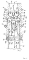
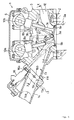
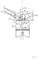
- Figures 1 and 2 will be used to describe a first embodiment of a four-cycle engine air intake device conforming to the invention of claim 1.
- Figure 1 is a sectional front view of said engine embodiment (along line I-I of Figure 2) while Figure 2 is a sectional top view (along line II-II of Figure 1).
- 1 is an engine equipped with the air intake control device of the present embodiment, and it is a water cooled, four-cycle, four-cylinder, five-valve engine.
- the cylinder head 3 of said engine 1 is mounted atop the cylinder block 2 and is held in place by head bolts 6.
- a head cover 4 is also attached to the top mating surface of the cylinder head 3.
- cylinder bores (cylinders) 2a are formed in a row in the foregoing cylinder block 2, and concave areas 3a, which together with the foregoing cylinder bores 2a comprise the combustion chambers, are present in the bottom surface of the cylinder head 3.
- the center air intake valve opening 5a is present in these concave combustion areas 3a on one side (the left side in Figure 2) of the center line C that runs parallel to the camshaft and through the cylindrical axis A, and in the center in the camshaft direction (the vertical direction in Figure 2).
- left and right (first and second) side air intake valve openings 5b, 5c are present in each of the cylinders 5.
- spark plugs 17 are threaded into the foregoing concave combustion areas 3a in their approximate centers so that their electrodes are situated at the boundary with the combustion chambers.
- the foregoing center, left and right side air intake valve openings 5a, 5b, 5c are respectively opened and closed by center, left and right side air intake valves 7a, 7b and 7c.
- the foregoing left and right exhaust valve openings 5d, 5e are also opened and closed by left and right exhaust valves 7d, 7e.
- the foregoing air intake valves 7a-7c and exhaust valves 7d, 7e are biased into a normally closed position by valve springs 9a, 9b, and are opened and closed by valve lifters 8a, 8b that are driven by the air intake and exhaust camshafts 10a, 10b.
- the angle ⁇ 1 formed between the axial line B1 of the foregoing center air intake valve 7a and the cylindrical axis A is smaller than the angle ⁇ 2 formed between the axes of the left and right side air intake valves 7b, 7c and the cylindrical axis A.
- the center air intake valve 7a is more upright than the side air intake valves 7b, 7c.
- the foregoing center, left and right side air intake valve openings 5a, 5b, 5c are respectively connected with the center, left and right side branch passages 11a, 11b, 11c.
- a valve body 13 is installed in an external connection opening 11f located near the outer wall of the cylinder head 3 in the air intake passage 11 that makes up said three branch passages 11a-11c, and that opening 11f connects to an air intake manifold 14.
- the partitioning wall 11e between the foregoing center branch passage 11a and the right side branch passage 11c connects with the partitioning wall 14a of the foregoing air intake manifold 14 from the partitioning wall 13b of the foregoing valve body 13.
- the partitioning wall 11d which lies between the center branch passage 11a and the left side branch passage 11b, extends to the vicinity of the foregoing valve body 13.
- the air intake passage 11 in this embodiment is divided into a compound passage consisting of two branches, the center branch passage 11a and the left side branch passage 11b, as well as a right side air intake passage 11c that forms a single air intake passage.
- the cross-section of the foregoing compound air intake passage it forms a small, approximately semi-circular shape, while the cross section of the foregoing single air intake passage is approximately circular.
- valve body 13 is plate-shaped and spans the length of the four cylinders, and a boss 13c' is formed on the center top surface in the foregoing left side branch passage (single air intake passage) 11b of said valve body 13.
- This boss 13c' accommodates the mounting of a fuel injection valve 16, so that the injection nozzle 16a of said valve 16 points at a fuel guide groove 11h that is present in the ceiling of the foregoing right side branch 11c that leads toward the foregoing right side intake valve opening 5c.
- the foregoing valve body 13 is partitioned by a partitioning wall 13b into a single air intake hole 13a and a compound air intake hole 13c. Also, inside of this valve body 13 is a valve plate 15a affixed to a valve shaft 15b that is inserted across the body 13 in the camshaft direction and comprises a valve that opens and closes. This valve plate 15a is positioned in the compound air intake hole 13c in the foregoing valve body 13 so that it can open and close both the foregoing center branch passage 11a and the left side branch passage 11b.
- valve shaft 15b is connected to a valve opening-and-closing drive mechanism which drives said valve shaft 15b open and closed; said drive mechanism is controlled by open and close drive signals generated by an ECU.
- a bypass hole 11g is present in the partitioning wall 11e dividing the foregoing compound air intake passage and single air intake passage, between the foregoing fuel injection nozzle 16a and the center air intake valve opening 5a. A part of the fuel from the foregoing fuel injection valve 16 passes through this bypass port 11g and enters the center branch passage 11a.
- a signal generated by the foregoing ECU causes the drive mechanism to turn the foregoing valve shaft 15b into the fully closed position.
- This feature causes the valve plate 15a to completely close the compound air intake hole 13c so that all the intake air is concentrated in the right side branch passage 11c, which functions as the primary air intake passage.
- a swirl is generated that follows the inside circumference of the cylinder.
- the left and right side air intake valve openings 5b, 5c are separated by a great distance in the camshaft direction, in other words, in this camshaft direction, they are positioned closer to the inside circumferential surface of the cylinder 5 As a result, the inflow into the cylinder 5 of the intake air generates a stronger swirl along the inside circumferential surface of the cylinder 5.
- the fuel spray from the fuel injection valve 16 is directed primarily toward the right air intake valve opening 5c, but a part of it passes through the bypass port 11g, through the center branch passage 11a, to the back surface of the center air intake valve 7.
- the fuel from the foregoing bypass port 11g cools the area of the center air intake valve 7a, thereby averting the above described abnormal temperature increases.
- a signal from the foregoing ECU causes the drive mechanism to rotate the foregoing valve shaft 15b to the fully open position, and as a result, in addition to the air intake from the foregoing primary passage, the right side branch passage 11c, air flows into the cylinder 5 also from the centre and left side branch passages 11a, 11b, which function as secondary passages.
- the majority of the fuel is directed toward the right side air intake passage 7c toward the right side air intake valve 5c, so that the intake vapor from the left side air intake valve opening 5b is just air, thereby creating so-called stratified combustion.
- the partitioning wall 11d of the center and left side branch passage 11a, 11b extends to the vicinity the opening and closing valve, but this partitioning wall 11d may be as shown in Figure 4, shorter and positioned more toward the air intake side from the bypass port. In this case, the cooling effect would also extend to the area of the left side air intake valve 7b and its opening 5b.
- Figures 3 through 8 show another embodiment (second embodiment) involving engine air-intake control devices of the inventions in Claims 2, 3, 5 and 6.
- parts identical to or corresponding to those in Figures 1 and 2 bear the same reference numbers.
- the partitioning wall 11d between the center branch passage 11a and the left side branch passage 11b is set to be short, to extend to the vicinity of the inside wall of the cylinder bore 2a.
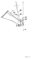
- the right side branch passage 11c, which functions as the primary passage, and the left side air intake branch passage 11b, which functions as the secondary passage have vastly differing shapes, particularly with regard to their ceiling surface and bend areas going toward the air intake valve opening 5b, 5c. While the right side branch passage 11c is shaped to assure the generation of a strong swirl or tumble during periods of low air intake, the left side branch passage 11b, is shaped to provide as little as possible air intake drag during operations requiring high volumes of air intake, thereby increasing the maximum air intake volume.
- the angle ⁇ 4 subtended between the ceiling of the foregoing right side branch passage 11c and the cylindrical axis A is smaller than the angle ⁇ 3 subtended between the ceiling of the foregoing left side branch passage 11b and the cylindrical axis A, and further, the closer to the air intake valve opening 5c, the lower the ceiling height, and the less the opening.
- the throat bend area S2 which runs parallel to the valve stem B2 is designed to be very short.
- the height of the left side branch passage 11b changes less dramatically, and the area toward the air intake valve opening 5b curves gradually with a comparatively large curvature radius. Furthermore, the throat area S1, which runs parallel to the valve stem B1, is designed to be longer than the foregoing S2, and this decreases the air intake drag so that the maximum air intake volume may be achieved. Also, the center branch passage 11a is of the same shape as the foregoing left side branch passage 11b, in other words, it is designed to have low air intake drag.
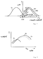
- the shape of the cam beaks has been designed in such manner that the lift curve IN1 for the foregoing right side air intake valve 7c and the lift curve IN2 for the center and left side air intake valves 7a, 7b and their respective open intervals P1, P2 and maximum apertures L1, L2, shall be different.
- the opening timing is delayed and the closing timing is advanced for the right side intake valve 7c, positioned in the primary passage, in order that its opening interval be shorter compared with the timing for the center and left side air intake valves 7a, 7b which are located in the secondary air intake passage, and the maximum aperture (lift) is lower as well.
- the secondary passage center and left side branch passage 11a, 11b
- the primary passage right side branch passage 11c
- the right side branch passage 11c is shaped to facilitate the generation of a swirl or tumble, a stronger swirling and tumbling action is generated.
- the right side air intake valve opening 5c is positioned toward the camshaft 10a so that the intake air entering it flows horizontally along the inside circumference of the cylinder wall to generate a swirl.
- the opening timing is delayed for the foregoing primary passage, i.e. the right side air intake valve 7c, there is but a small overlap D1 with the lift curve EX for the exhaust side.
- the closing timing is delayed, the air intake blow-back is reduced, and low speed torque is thereby improved.
- the secondary passage is fully open, with the intake air flowing through both the primary and secondary passages into the cylinder 5.
- the center and left side branch passages 11a, 11b that compose the secondary air intake passage have been shaped to present only little air intake drag, thereby increasing the maximum air intake volume.
- the opening interval T2 and the lift L2 for the center and left side air intake valves 7a, 7b located in the secondary air intake passage have been set to comparatively large values, and this feature serves to increase the air intake volume, which, as a result, increases torque during periods of high air intake.
- the right side branch passage 11c that composes the primary passage has a shape (swirl port) that entails relatively high air intake drag to facilitate the generation of a swirl, which is detrimental to increasing the maximum air intake volume, but this swirl port is just one of three passages and comprises about 1/3 of the total. Accordingly, those effects are minimal compared with designs using only two of the foregoing air intake passages.
- FIG. 8 is a graph to explain the torque-enhancing effects of the present embodiment.
- T3 represents a torque curve of a prior art engine that does not have primary and secondary passages
- torque curve T1 shows the effect in improving torque when the primary passage is a swirl port, and when using IN1 as the lift curve.
- Torque curve T2 shows the torque improvements when using a low air intake drag secondary passage as described above and the IN2 lift curve. According to this Figure, torque is improved across a broad range from the low speed operating range through the high speed operating range.
- the fuel injection valve 16 is located in the primary passage, which is composed of the center and left side branch passages 11a, 11b.
- a disc-shaped valve plate 15c is located in the secondary passage 11c which is composed of the right side branch passage 11c.
- the lift curves for the center air intake valve 7a and the left side air intake valve 7b have been set to IN1
- the lift curve for the right side air intake valve 7c has been set to IN2.
- the present embodiment provides stabilized idling RPM due to good combustion during periods of low air intake and it also increases low speed torque; torque is also improved during periods of high RPM.
- an opening 11h is made between the partitioning wall 11e of air intake passage 11 and the partitioning wall 13b of the valve body (a notched area in the partitions), so that the injection nozzle 16a of the fuel injection valve 16 can be located in the vicinity of the top of said opening, and the nozzle shape of said injection nozzles 16a is selected so that it sprays fuel from the foregoing opening 11a toward the right side passage 11c and the center branch passage 11a and left side branch passage 11b.
- the cross sectional shape of the air intake passage 11 is oval, and it represents one common passage, which branches just upstream of the various intake valve openings into a left side air intake passage 11b, center air intake passage 11a, and right side air intake passage 11c.
- the valve plate 15d of the valve body 13 is also oval in shape, largest in the width dimension, and corresponds to the shape of the upstream opening of the foregoing air intake passage 11, but the plate 15d has a notch 15e.
- this notch 15e is formed to that the intake flow is diverted to the corner area between the ceiling surface and the right side wall surface of the intake passage 11.
- the rotation of the foregoing valve plate 15d into the closed position causes the intake flow to be diverted toward the right side air intake passage area 11c, which is the primary passage, to generate a strong flow inside of the cylinder.
- the nozzle 16a of the fuel injection valve 16 is also positioned to spray fuel toward this right side air intake passage 11c. It is also possible to position the nozzle 16a' of the fuel injection valve 16 in the approximate center of the air intake passage 11, and to shape it to spray fuel toward the left and right side air intake passages 11b, 11c.
- this embodiment also constrains the angle ⁇ 4 between the ceiling of the right side air intake passage 11c and the cylindrical axis A to be smaller than the angle ⁇ 3 between the ceiling of the left side air intake passage 11b and the cylindrical axis A, and the passage height is lower as well. Further, the throat area S2 of the right side air intake passage 11c is very short. Also, in the current embodiment, because of the foregoing angle ⁇ 3 for the left side air intake passage area 11b, there is a gradual "R" shaped curve in the cylindrical axis direction, and the throat area S1 from the curvature to the air intake opening 5b is longer than the throat area S2 of the above described right side air intake passage 11a. This feature lowers the air intake drag, and even further boosts the maximum air intake volume.
- the intake air is diverted by the notch 15e in the valve plate 15 toward the right side air intake passage, and moreover, the shape of said right side air intake passage is one that facilitates tumble and swirl generation, which assures, strong flowing action inside the cylinder.
- the valve that opens and closes the compound air intake passage is closed, so that the intake air enters the cylinder only through the single air intake passage, and in addition, a bypass port inside this single air intake passages supplies a part of the fuel to the inside of the compound air intake passage, thereby inhibiting temperature increases in the vicinity of the center air intake valve opening while generating a swirl.
- the valve that opens and closes the first air intake passage is closed, so that the intake air enters the cylinder only through the second air intake valve opening, and additionally the opening interval in the lift curve for said second air intake valve is set to be shorter to decrease the overlap with the exhaust valves, thereby stabilizing the idling RPM while avoiding residual exhaust gas retention in the combustion chamber to improve low speed torque.
- the first air intake passage is fully open and the intake air enters the cylinder from both the first and second air intake passages, and in addition, the opening interval in the lift curve for said first air intake valve is set to be greater, thereby increasing the maximum air intake volume to improve output during high speed operations.
- the shape of the air intake control valve facilitates the generation of a tumbling action by the intake air by focussing the air intake on the second side air intake passage (primary passage), and moreover, because this control valve is located distantly in the camshaft direction, in other words, in the vicinity of the circumferential surface of the cylinder, the air that is introduced from this second side air intake valve opening easily generates a swirl inside of the cylinder, with the effect of improving the flows inside the cylinder.
- the intake air enters the cylinder both through the secondary air intake passage, which is designed to have low intake drag and through the first air intake passage to increase the maximum intake volume. Since this primary passage is shaped to generate swirls and tumbles, the intake resistance is relatively high, but since its cross section accounts for only about 1/3 of the total passage cross section, it is possible to restrict the decrease in the maximum air intake volume attributable to the port shape which is designed to improve flows in the cylinder.
Landscapes
- Engineering & Computer Science (AREA)
- Chemical & Material Sciences (AREA)
- Combustion & Propulsion (AREA)
- Mechanical Engineering (AREA)
- General Engineering & Computer Science (AREA)
- Cylinder Crankcases Of Internal Combustion Engines (AREA)
- Combustion Methods Of Internal-Combustion Engines (AREA)
Applications Claiming Priority (3)
| Application Number | Priority Date | Filing Date | Title |
|---|---|---|---|
| JP27647994A JP3457751B2 (ja) | 1994-08-31 | 1994-11-10 | 4サイクルエンジンの吸気制御装置 |
| JP276479/94 | 1994-11-10 | ||
| JP27647994 | 1994-11-10 |
Publications (3)
| Publication Number | Publication Date |
|---|---|
| EP0711906A2 true EP0711906A2 (de) | 1996-05-15 |
| EP0711906A3 EP0711906A3 (de) | 1997-05-07 |
| EP0711906B1 EP0711906B1 (de) | 2000-04-26 |
Family
ID=17570033
Family Applications (1)
| Application Number | Title | Priority Date | Filing Date |
|---|---|---|---|
| EP95117804A Expired - Lifetime EP0711906B1 (de) | 1994-11-10 | 1995-11-10 | Brennkraftmaschine |
Country Status (3)
| Country | Link |
|---|---|
| US (1) | US5636613A (de) |
| EP (1) | EP0711906B1 (de) |
| DE (1) | DE69516482T2 (de) |
Cited By (3)
| Publication number | Priority date | Publication date | Assignee | Title |
|---|---|---|---|---|
| WO2001036796A1 (en) * | 1999-11-12 | 2001-05-25 | Siemens Canada Limited | Integrated swirl control valve |
| EP1111218A3 (de) * | 1999-12-21 | 2002-05-15 | Ford Global Technologies, Inc. | Luftbewegungssteuerklappe im oberen Einlasskrümmer |
| CN106762106A (zh) * | 2015-11-23 | 2017-05-31 | 现代自动车株式会社 | 用于车辆的发动机结构 |
Families Citing this family (10)
| Publication number | Priority date | Publication date | Assignee | Title |
|---|---|---|---|---|
| US5840490A (en) * | 1995-06-07 | 1998-11-24 | Mcmaster University | Telomerase activity associated with hematological and colorectal malignancies |
| DE19535047A1 (de) * | 1995-09-21 | 1997-03-27 | Bosch Gmbh Robert | Brennstoffeinspritzventil |
| EP1001160B1 (de) | 1998-11-16 | 2003-05-14 | Sanshin Kogyo Kabushiki Kaisha | Brennkraftmaschine |
| US6895925B2 (en) | 2002-09-18 | 2005-05-24 | Daimlerchrysler Corporation | Internal combustion engine having three valves per cylinder |
| JP4072676B2 (ja) * | 2002-12-24 | 2008-04-09 | スズキ株式会社 | エンジンの可変動弁装置 |
| JP2005273527A (ja) * | 2004-03-24 | 2005-10-06 | Kawasaki Heavy Ind Ltd | レジャービィークル用エンジン |
| US7096849B1 (en) * | 2005-07-12 | 2006-08-29 | Steeda Autosports, Inc. | Charge motion control plate kit |
| US7647916B2 (en) * | 2005-11-30 | 2010-01-19 | Ford Global Technologies, Llc | Engine with two port fuel injectors |
| JP6130794B2 (ja) * | 2014-02-06 | 2017-05-17 | 株式会社クボタ | エンジン |
| US9677467B2 (en) * | 2014-05-13 | 2017-06-13 | Suzuki Motor Corporation | Vertical engine |
Family Cites Families (12)
| Publication number | Priority date | Publication date | Assignee | Title |
|---|---|---|---|---|
| US4617896A (en) * | 1985-03-14 | 1986-10-21 | Yamaha Hatsudoki Kabushiki Kaisha | Internal combustion engine having three intake valves per cylinder |
| US4667636A (en) * | 1985-03-22 | 1987-05-26 | Toyota Jidosha Kabushiki Kaisha | Fuel injection type internal combustion engine |
| JPH03279623A (ja) * | 1990-03-27 | 1991-12-10 | Mazda Motor Corp | 多弁式エンジンの制御装置 |
| JPH03281915A (ja) * | 1990-03-29 | 1991-12-12 | Mazda Motor Corp | 吸気多弁式エンジン |
| JP2887797B2 (ja) * | 1991-02-15 | 1999-04-26 | ヤマハ発動機株式会社 | 4サイクルエンジンの吸気装置 |
| EP0595316B1 (de) * | 1992-10-28 | 1997-04-23 | Yamaha Hatsudoki Kabushiki Kaisha | Zylinderkopf und Ventilanordnung einer Mehrventil-Brennkraftmaschine |
| JP3426296B2 (ja) * | 1993-08-27 | 2003-07-14 | ヤマハ発動機株式会社 | エンジンの吸気装置 |
| JPH07150945A (ja) * | 1993-11-26 | 1995-06-13 | Yamaha Motor Co Ltd | 4サイクルエンジンの燃焼室構造 |
| US5477823A (en) * | 1994-01-25 | 1995-12-26 | Yamaha Hatsudoki Kabushiki Kaisha | Control valve for engine intake control system |
| JP3319645B2 (ja) * | 1994-02-17 | 2002-09-03 | ヤマハ発動機株式会社 | エンジンの吸気制御装置 |
| US5454357A (en) * | 1994-12-12 | 1995-10-03 | General Motors Corporation | Slide port valve for an internal combustion engine |
| US5526789A (en) * | 1995-05-04 | 1996-06-18 | Ford Motor Company | Internal combustion engine intake system with variable tuning |
-
1995
- 1995-11-09 US US08/555,528 patent/US5636613A/en not_active Expired - Lifetime
- 1995-11-10 DE DE69516482T patent/DE69516482T2/de not_active Expired - Fee Related
- 1995-11-10 EP EP95117804A patent/EP0711906B1/de not_active Expired - Lifetime
Cited By (4)
| Publication number | Priority date | Publication date | Assignee | Title |
|---|---|---|---|---|
| WO2001036796A1 (en) * | 1999-11-12 | 2001-05-25 | Siemens Canada Limited | Integrated swirl control valve |
| US6662772B1 (en) | 1999-11-12 | 2003-12-16 | Siemens Canada Limited | Integrated swirl control valve |
| EP1111218A3 (de) * | 1999-12-21 | 2002-05-15 | Ford Global Technologies, Inc. | Luftbewegungssteuerklappe im oberen Einlasskrümmer |
| CN106762106A (zh) * | 2015-11-23 | 2017-05-31 | 现代自动车株式会社 | 用于车辆的发动机结构 |
Also Published As
| Publication number | Publication date |
|---|---|
| EP0711906A3 (de) | 1997-05-07 |
| US5636613A (en) | 1997-06-10 |
| DE69516482D1 (de) | 2000-05-31 |
| DE69516482T2 (de) | 2000-09-07 |
| EP0711906B1 (de) | 2000-04-26 |
Similar Documents
| Publication | Publication Date | Title |
|---|---|---|
| US5676107A (en) | Direct injection diesel engine | |
| EP0711906B1 (de) | Brennkraftmaschine | |
| US5551393A (en) | Induction system for engine | |
| JP3494284B2 (ja) | 4ストロークサイクル内燃機関の吸気ポート構造 | |
| EP1344926B1 (de) | Einlasskanal einer Brennkraftmaschine | |
| US5762042A (en) | Internal combustion engine | |
| EP0529676B1 (de) | Einlasssystem für eine Brennkraftmaschine | |
| US5826560A (en) | Engine combustion chamber and method of operation | |
| US6213090B1 (en) | Engine cylinder head | |
| JPH057555B2 (de) | ||
| KR100302435B1 (ko) | 내연기관 | |
| JP3718902B2 (ja) | エンジンの吸気ポート構造 | |
| US7273032B2 (en) | Engine induction system | |
| JP3402640B2 (ja) | エンジンの吸気制御装置 | |
| US6173693B1 (en) | Cylinder head | |
| US6189503B1 (en) | Porting arrangement for direct injected engine | |
| US5727521A (en) | Cylinder head of an internal-combustion engine | |
| EP0640754B1 (de) | Brennkraftmaschine | |
| US5060616A (en) | Intake system for multiple-valve engine | |
| JP2772767B2 (ja) | 内燃機関における吸気ポート構造 | |
| US20100037840A1 (en) | Internal combustion engine | |
| JPH08135455A (ja) | エンジンの吸気制御装置 | |
| JPH0555691B2 (de) | ||
| JP3506769B2 (ja) | エンジンの吸気制御装置 | |
| JP3329405B2 (ja) | 2バルブエンジンの吸気制御構造 |
Legal Events
| Date | Code | Title | Description |
|---|---|---|---|
| PUAI | Public reference made under article 153(3) epc to a published international application that has entered the european phase |
Free format text: ORIGINAL CODE: 0009012 |
|
| AK | Designated contracting states |
Kind code of ref document: A2 Designated state(s): DE FR GB IT |
|
| PUAL | Search report despatched |
Free format text: ORIGINAL CODE: 0009013 |
|
| AK | Designated contracting states |
Kind code of ref document: A3 Designated state(s): DE FR GB IT |
|
| 17P | Request for examination filed |
Effective date: 19971029 |
|
| 17Q | First examination report despatched |
Effective date: 19971128 |
|
| GRAG | Despatch of communication of intention to grant |
Free format text: ORIGINAL CODE: EPIDOS AGRA |
|
| GRAG | Despatch of communication of intention to grant |
Free format text: ORIGINAL CODE: EPIDOS AGRA |
|
| GRAH | Despatch of communication of intention to grant a patent |
Free format text: ORIGINAL CODE: EPIDOS IGRA |
|
| GRAH | Despatch of communication of intention to grant a patent |
Free format text: ORIGINAL CODE: EPIDOS IGRA |
|
| GRAA | (expected) grant |
Free format text: ORIGINAL CODE: 0009210 |
|
| AK | Designated contracting states |
Kind code of ref document: B1 Designated state(s): DE FR GB IT |
|
| PG25 | Lapsed in a contracting state [announced via postgrant information from national office to epo] |
Ref country code: IT Free format text: LAPSE BECAUSE OF FAILURE TO SUBMIT A TRANSLATION OF THE DESCRIPTION OR TO PAY THE FEE WITHIN THE PRESCRIBED TIME-LIMIT;WARNING: LAPSES OF ITALIAN PATENTS WITH EFFECTIVE DATE BEFORE 2007 MAY HAVE OCCURRED AT ANY TIME BEFORE 2007. THE CORRECT EFFECTIVE DATE MAY BE DIFFERENT FROM THE ONE RECORDED. Effective date: 20000426 |
|
| REF | Corresponds to: |
Ref document number: 69516482 Country of ref document: DE Date of ref document: 20000531 |
|
| ET | Fr: translation filed | ||
| PLBE | No opposition filed within time limit |
Free format text: ORIGINAL CODE: 0009261 |
|
| STAA | Information on the status of an ep patent application or granted ep patent |
Free format text: STATUS: NO OPPOSITION FILED WITHIN TIME LIMIT |
|
| 26N | No opposition filed | ||
| REG | Reference to a national code |
Ref country code: GB Ref legal event code: IF02 |
|
| PGFP | Annual fee paid to national office [announced via postgrant information from national office to epo] |
Ref country code: FR Payment date: 20021108 Year of fee payment: 8 |
|
| PG25 | Lapsed in a contracting state [announced via postgrant information from national office to epo] |
Ref country code: FR Free format text: LAPSE BECAUSE OF NON-PAYMENT OF DUE FEES Effective date: 20040730 |
|
| REG | Reference to a national code |
Ref country code: FR Ref legal event code: ST |
|
| PGFP | Annual fee paid to national office [announced via postgrant information from national office to epo] |
Ref country code: DE Payment date: 20081107 Year of fee payment: 14 |
|
| PGFP | Annual fee paid to national office [announced via postgrant information from national office to epo] |
Ref country code: GB Payment date: 20081105 Year of fee payment: 14 |
|
| GBPC | Gb: european patent ceased through non-payment of renewal fee |
Effective date: 20091110 |
|
| PG25 | Lapsed in a contracting state [announced via postgrant information from national office to epo] |
Ref country code: DE Free format text: LAPSE BECAUSE OF NON-PAYMENT OF DUE FEES Effective date: 20100601 |
|
| PG25 | Lapsed in a contracting state [announced via postgrant information from national office to epo] |
Ref country code: GB Free format text: LAPSE BECAUSE OF NON-PAYMENT OF DUE FEES Effective date: 20091110 |