EP0711943A2 - Vorrichtung zum Ausgeben heissen flüssigen Materials - Google Patents
Vorrichtung zum Ausgeben heissen flüssigen Materials Download PDFInfo
- Publication number
- EP0711943A2 EP0711943A2 EP95115911A EP95115911A EP0711943A2 EP 0711943 A2 EP0711943 A2 EP 0711943A2 EP 95115911 A EP95115911 A EP 95115911A EP 95115911 A EP95115911 A EP 95115911A EP 0711943 A2 EP0711943 A2 EP 0711943A2
- Authority
- EP
- European Patent Office
- Prior art keywords
- dispenser
- coil
- plunger
- fluid
- fixed pole
- Prior art date
- Legal status (The legal status is an assumption and is not a legal conclusion. Google has not performed a legal analysis and makes no representation as to the accuracy of the status listed.)
- Withdrawn
Links
- 239000012530 fluid Substances 0.000 title claims abstract description 159
- 239000000463 material Substances 0.000 title claims description 57
- 230000004044 response Effects 0.000 claims abstract description 5
- 230000005672 electromagnetic field Effects 0.000 claims description 17
- 230000005291 magnetic effect Effects 0.000 claims description 11
- 230000008878 coupling Effects 0.000 claims description 10
- 238000010168 coupling process Methods 0.000 claims description 10
- 238000005859 coupling reaction Methods 0.000 claims description 10
- 238000000034 method Methods 0.000 claims description 9
- 238000005461 lubrication Methods 0.000 claims description 6
- 125000006850 spacer group Chemical group 0.000 claims description 6
- 230000013011 mating Effects 0.000 claims description 4
- 230000005389 magnetism Effects 0.000 claims description 2
- 239000000853 adhesive Substances 0.000 abstract description 30
- 230000001070 adhesive effect Effects 0.000 abstract description 30
- 239000004831 Hot glue Substances 0.000 abstract description 15
- 238000004804 winding Methods 0.000 description 16
- 239000003570 air Substances 0.000 description 15
- 238000012546 transfer Methods 0.000 description 11
- 238000009413 insulation Methods 0.000 description 7
- 230000008901 benefit Effects 0.000 description 6
- 238000004382 potting Methods 0.000 description 6
- 239000000758 substrate Substances 0.000 description 6
- 230000004888 barrier function Effects 0.000 description 5
- XAGFODPZIPBFFR-UHFFFAOYSA-N aluminium Chemical compound [Al] XAGFODPZIPBFFR-UHFFFAOYSA-N 0.000 description 4
- 229910052782 aluminium Inorganic materials 0.000 description 4
- 239000011324 bead Substances 0.000 description 4
- 239000004020 conductor Substances 0.000 description 4
- 238000013461 design Methods 0.000 description 4
- 239000012943 hotmelt Substances 0.000 description 4
- 229910000831 Steel Inorganic materials 0.000 description 3
- 239000012080 ambient air Substances 0.000 description 3
- 238000004891 communication Methods 0.000 description 3
- 230000003247 decreasing effect Effects 0.000 description 3
- 230000000694 effects Effects 0.000 description 3
- 239000000696 magnetic material Substances 0.000 description 3
- 230000000717 retained effect Effects 0.000 description 3
- 239000007787 solid Substances 0.000 description 3
- 229910001220 stainless steel Inorganic materials 0.000 description 3
- 239000010935 stainless steel Substances 0.000 description 3
- 239000010959 steel Substances 0.000 description 3
- 238000002474 experimental method Methods 0.000 description 2
- 239000003302 ferromagnetic material Substances 0.000 description 2
- 239000011152 fibreglass Substances 0.000 description 2
- 230000004907 flux Effects 0.000 description 2
- 238000007789 sealing Methods 0.000 description 2
- 229910001369 Brass Inorganic materials 0.000 description 1
- 239000004593 Epoxy Substances 0.000 description 1
- 229920000784 Nomex Polymers 0.000 description 1
- 230000009286 beneficial effect Effects 0.000 description 1
- 230000015572 biosynthetic process Effects 0.000 description 1
- 239000010951 brass Substances 0.000 description 1
- 230000015556 catabolic process Effects 0.000 description 1
- 150000001875 compounds Chemical class 0.000 description 1
- 239000012141 concentrate Substances 0.000 description 1
- 230000007812 deficiency Effects 0.000 description 1
- -1 for example Substances 0.000 description 1
- 239000011521 glass Substances 0.000 description 1
- 238000010438 heat treatment Methods 0.000 description 1
- 239000011810 insulating material Substances 0.000 description 1
- 239000012774 insulation material Substances 0.000 description 1
- 230000003993 interaction Effects 0.000 description 1
- 238000002955 isolation Methods 0.000 description 1
- 239000007788 liquid Substances 0.000 description 1
- 238000004519 manufacturing process Methods 0.000 description 1
- 238000012986 modification Methods 0.000 description 1
- 230000004048 modification Effects 0.000 description 1
- 239000004763 nomex Substances 0.000 description 1
- 239000002245 particle Substances 0.000 description 1
- 239000000565 sealant Substances 0.000 description 1
Images




Classifications
-
- B—PERFORMING OPERATIONS; TRANSPORTING
- B67—OPENING, CLOSING OR CLEANING BOTTLES, JARS OR SIMILAR CONTAINERS; LIQUID HANDLING
- B67D—DISPENSING, DELIVERING OR TRANSFERRING LIQUIDS, NOT OTHERWISE PROVIDED FOR
- B67D99/00—Subject matter not provided for in other groups of this subclass
-
- B—PERFORMING OPERATIONS; TRANSPORTING
- B05—SPRAYING OR ATOMISING IN GENERAL; APPLYING FLUENT MATERIALS TO SURFACES, IN GENERAL
- B05C—APPARATUS FOR APPLYING FLUENT MATERIALS TO SURFACES, IN GENERAL
- B05C5/00—Apparatus in which liquid or other fluent material is projected, poured or allowed to flow on to the surface of the work
- B05C5/02—Apparatus in which liquid or other fluent material is projected, poured or allowed to flow on to the surface of the work the liquid or other fluent material being discharged through an outlet orifice by pressure, e.g. from an outlet device in contact or almost in contact, with the work
-
- B—PERFORMING OPERATIONS; TRANSPORTING
- B05—SPRAYING OR ATOMISING IN GENERAL; APPLYING FLUENT MATERIALS TO SURFACES, IN GENERAL
- B05C—APPARATUS FOR APPLYING FLUENT MATERIALS TO SURFACES, IN GENERAL
- B05C5/00—Apparatus in which liquid or other fluent material is projected, poured or allowed to flow on to the surface of the work
- B05C5/001—Apparatus in which liquid or other fluent material is projected, poured or allowed to flow on to the surface of the work incorporating means for heating or cooling the liquid or other fluent material
-
- B—PERFORMING OPERATIONS; TRANSPORTING
- B05—SPRAYING OR ATOMISING IN GENERAL; APPLYING FLUENT MATERIALS TO SURFACES, IN GENERAL
- B05C—APPARATUS FOR APPLYING FLUENT MATERIALS TO SURFACES, IN GENERAL
- B05C5/00—Apparatus in which liquid or other fluent material is projected, poured or allowed to flow on to the surface of the work
- B05C5/02—Apparatus in which liquid or other fluent material is projected, poured or allowed to flow on to the surface of the work the liquid or other fluent material being discharged through an outlet orifice by pressure, e.g. from an outlet device in contact or almost in contact, with the work
- B05C5/0225—Apparatus in which liquid or other fluent material is projected, poured or allowed to flow on to the surface of the work the liquid or other fluent material being discharged through an outlet orifice by pressure, e.g. from an outlet device in contact or almost in contact, with the work characterised by flow controlling means, e.g. valves, located proximate the outlet
-
- B—PERFORMING OPERATIONS; TRANSPORTING
- B67—OPENING, CLOSING OR CLEANING BOTTLES, JARS OR SIMILAR CONTAINERS; LIQUID HANDLING
- B67D—DISPENSING, DELIVERING OR TRANSFERRING LIQUIDS, NOT OTHERWISE PROVIDED FOR
- B67D7/00—Apparatus or devices for transferring liquids from bulk storage containers or reservoirs into vehicles or into portable containers, e.g. for retail sale purposes
- B67D7/06—Details or accessories
- B67D7/80—Arrangements of heating or cooling devices for liquids to be transferred
-
- B—PERFORMING OPERATIONS; TRANSPORTING
- B05—SPRAYING OR ATOMISING IN GENERAL; APPLYING FLUENT MATERIALS TO SURFACES, IN GENERAL
- B05B—SPRAYING APPARATUS; ATOMISING APPARATUS; NOZZLES
- B05B1/00—Nozzles, spray heads or other outlets, with or without auxiliary devices such as valves, heating means
- B05B1/30—Nozzles, spray heads or other outlets, with or without auxiliary devices such as valves, heating means designed to control volume of flow, e.g. with adjustable passages
- B05B1/3033—Nozzles, spray heads or other outlets, with or without auxiliary devices such as valves, heating means designed to control volume of flow, e.g. with adjustable passages the control being effected by relative coaxial longitudinal movement of the controlling element and the spray head
- B05B1/304—Nozzles, spray heads or other outlets, with or without auxiliary devices such as valves, heating means designed to control volume of flow, e.g. with adjustable passages the control being effected by relative coaxial longitudinal movement of the controlling element and the spray head the controlling element being a lift valve
- B05B1/3046—Nozzles, spray heads or other outlets, with or without auxiliary devices such as valves, heating means designed to control volume of flow, e.g. with adjustable passages the control being effected by relative coaxial longitudinal movement of the controlling element and the spray head the controlling element being a lift valve the valve element, e.g. a needle, co-operating with a valve seat located downstream of the valve element and its actuating means, generally in the proximity of the outlet orifice
- B05B1/3053—Nozzles, spray heads or other outlets, with or without auxiliary devices such as valves, heating means designed to control volume of flow, e.g. with adjustable passages the control being effected by relative coaxial longitudinal movement of the controlling element and the spray head the controlling element being a lift valve the valve element, e.g. a needle, co-operating with a valve seat located downstream of the valve element and its actuating means, generally in the proximity of the outlet orifice the actuating means being a solenoid
Definitions
- This invention is directed to a fluid dispenser, such as for the dispensing of viscous fluids, such as adhesives, sealants and caulks. More particularly, this invention is directed to an electromagnetically actuated fluid dispenser for dispensing heated fluid materials such as, for example, hot melt adhesives.
- the current passing therethrough When the coil of an electromagnetic dispenser is energized, the current passing therethrough generates heat due to the resistance of the windings of the coil. Specifically, the heat generated is a function of the current squared and the resistance (I2R) of the windings. As the magnitude of the current passing through the windings increases and/or the length of time the current passing through the windings increases, i.e., longer actuation (on cycle) with a shorter off cycle, more and more heat is generated, thus raising the temperature of the coil. If the heat generated causes the temperature to rise too high, the insulation of the coil may degrade and break down, which may eventually cause the dispenser to fail.
- hot melt adhesives In the dispensing of heated fluid materials, such as adhesives commonly known as hot melt adhesives, the fluid material itself may transfer additional heat to the coil. This additional heat increases the temperature of the coil, thus decreasing the allowable temperature rise that can be tolerated by the coil resulting from the current passing through the windings.
- hot melt adhesive application temperatures it is not uncommon for hot melt adhesive application temperatures to be in the range from about 121°C (250°F) to about 218°C (425°F) or higher. As the application temperature of the adhesive increases, more heat is available to be transferred to the coil. Thus the amount of heat that can be generated by the current passing through the coil in order to avoid exceeding the coil insulation rating is decreased. As such, the allowable energy available to drive the plunger is reduced.
- the application temperature of the adhesive may even be in excess of the temperature ratings of standard electromagnetic coil designs, making the use of an electrically driven dispenser impractical.
- hot melt adhesives dispensed at lower temperatures generally transfer less heat to the coil, thus allowing the coil itself to generate more energy (and in turn more heat) before thermal breakdown occurs.
- heaters are generally provided. Typically cartridge type heaters are provided in the dispenser or the associated service block, thus adding another source which can potentially add heat to the coil.
- closely mounting multiple electromagnetic guns together further compounds the problem of heating due to the heat transfer from one dispenser to an adjacent dispenser. For example, if three electromagnetic dispensers are mounted together, the two outer dispensers each add an incremental additional amount of heat to the center dispenser. This additional amount of heat may be sufficient enough to affect the thermal characteristics of the center dispenser, thus causing it to fail or vary in operating performance.
- a compact electromagnetic dispenser similar in size to the standard pneumatic dispensers, which is capable of operating at fast cycle rates, and is also capable of operating in a bank of dispenser so that closely spaced apart beads of material may be dispensed onto a substrate.
- an electromagnetic gun which is capable of operating not only at fast cycle rates, but is also capable of handling hot melt adhesives, in particular, those in excess of 300°F.
- Dynamic seals are seals in which an object moves therethrough, such as a plunger, and is used to prevent fluid from migrating past the seal. Eventually, a dynamic seal will lose its sealing properties. Once this occurs, the adhesive may migrate into various portions of the dispenser, causing damage or failure thereto. Therefore, it is also desirous to produce an electromagnetic gun which does not require the use of dynamic seals.
- Some hot melt adhesive dispensers have attempted to dissipate the heat generated by the coil by transferring it to the heated adhesive. This transfer, if it occurs at all, is not efficient due to a relatively low temperature differential between the fluid and the coil. Also, it is difficult to actually maintain the fluid at a desired temperature. This is because heat is not applied to, nor sensed directly from, the fluid itself. Rather, heat is applied to a portion of the dispenser and transferred to the fluid. Similarly, heat is sensed at a point in the dispenser itself. As such, the fluid temperature must be less than the thermal rating of the coil.
- the adhesive dispenser will have to be serviced.
- this would mean disconnecting the electrical connections, as well as disconnecting the dispenser from the supply of pressurized fluid, such as the hot melt adhesive.
- pressurized fluid such as the hot melt adhesive.
- it may be desirous to remove the dispenser completely from a service block or module there may be circumstances when only a portion of the dispenser needs to be serviced without having to disconnect the supply of fluid to the dispenser. For example, it may only be necessary to service and/or replace the coil of the dispenser, and therefore it would be advantageous to be able to remove the coil from the dispenser without having to remove the entire dispenser from a service block or manifold.
- this may allow the use of electrical coils having an insulation rating less than the temperature of the heated fluid. This may be accomplished, for example, by spacing the coil away from the heat fluid material.
- the coil may be spaced from the fluid chamber or bore and an insulating member placed there between.
- an air gap may be placed between the coil and the fluid chamber to provide a thermal barrier.
- an insulating material such as fiberglass, may be used to provide thermal isolation.
- the fluid flow path does not extend into the coil region, i.e. the central portion about which the coils are wound.
- This allows the dispenser to operate at higher power levels and/or at higher fluid application temperatures.
- This may be accomplished, for example, by a heat sink having a plurality of fins for radiating heat therefrom to the ambient air, thermally coupled to the coil for removing heat from the coil. This reduces the operating temperature of the coil, thereby increasing the efficiency of the coil and providing for improved performance at higher power levels/high cycle rates and/or higher application temperatures.
- hot melt adhesives are solids at ambient temperatures, they must be heated. As stated previously, heat is applied to the dispenser, either internally or externally, which is then transferred to the adhesive. If the application temperature is exceeded, the adhesive may begin to char which causes the material to produce unwanted solid particulates. If, on the other hand, the temperature falls below the given application temperature, the viscosity of the material will be increased. With increasing viscosity, the fluid material becomes increasingly more difficult to dispense. Changes in viscosity can result in more or less material being deposited onto the substrate, material not being deposited onto the substrate at the appropriate time, the material not shutting off at the appropriate time, and/or improper bonding of the substrate. Also, it is difficult to maintain the appropriate temperature of the hot melt within the dispenser. As a result, the emphasis has been on maintaining the temperature of the adhesive within the dispenser by adding heat and not with the dissipation of such heat from the dispenser to the ambient air.
- the heat sink provides a means for dissipating the internal heat generated by the coil windings and any heat that may be transferred from the heated fluid material to the windings.
- an apparatus for dispensing heated fluid materials comprising: a housing defining a fluid chamber, the fluid chamber extending from a first end to an outlet at a second end; a fixed pole disposed at the first end of the fluid chamber and extending away therefrom, wherein a portion of said fixed pole is in fluid contact with the fluid material within the fluid chamber; an inlet means for coupling the fluid chamber to a source of heated fluid material; a coil for generating an electromagnetic field, disposed about a portion of the fixed pole such that a portion of the pole extends beyond the coil to space the coil from the first end of the fluid passageway; and a plunger disposed within the fluid chamber adjacent to the fixed pole and mounted for reciprocal movement therein between closed and retracted positions when subjected to said electromagnetic field, such that when said plunger is in said closed position the outlet is blocked to prevent fluid flow therefrom and in said retracted position fluid flow is emitted from the outlet.
- an apparatus for dispensing hot melt adhesive comprising: a housing defining a fluid chamber; an inlet means for coupling the fluid chamber to a source of hot melt adhesive; a fixed pole extending into said fluid chamber such that a portion of an external surface of said fixed pole is in fluid communication with the adhesive; a coil for generating an electromagnetic field, disposed about a portion of the fixed pole and spaced from said fluid chamber; an insulating means, disposed between said fluid chamber and said coil for insulating the coil from the fluid chamber; a plunger disposed within the fluid chamber and mounted for reciprocal movement between a closed position and an open position, said plunger comprising a first portion, having a diameter closely approximating a diameter of the fluid chamber, and a second portion having a reduced diameter and extending from the first portion, the second portion including an engaging means for mating with a surface in the closed position, said plunger being spaced from said fixed pole in said closed position and adjacent to
- an apparatus for dispensing heated fluid materials comprising: housing, adapted for attaching to a service block or manifold, defining a fluid chamber, the fluid chamber extending from a first end to an outlet at a second end, said housing including an inlet means adapted for coupling the fluid chamber to a source of heated fluid material received from the service block or manifold; a fixed pole disposed at the first end of the fluid chamber and extending away therefrom, wherein only an end portion of said fixed pole is in fluid contact with the fluid material; a plunger disposed within the fluid chamber adjacent to the fixed pole and mounted for reciprocal movement therein between closed and retracted positions when subjected to said electromagnetic field, such that when said plunger is in said closed position the outlet is blocked to prevent fluid flow therefrom and in said retracted position fluid flow is emitted from the outlet; a coil assembly for generating an electromagnetic field, disposed about a portion of the fixed pole and spaced from the fluid chamber
- the method comprising the steps of releasably attaching a dispenser to a source of pressurized heated fluid and also releasably connecting the dispenser to a source of electrical power; then, at a later time, disconnecting the dispenser from the source of electrical power while maintaining the attachment to the source of heated fluid, to reveal an electrical pole of the dispenser without the heated fluid leaking from the dispenser.
- the method of establishing a magnetic gap of an electric dispenser comprising the steps of: assembling a fixed pole to a first body having a cavity therein and disposing a plunger and a spring within the cavity to form a first assembly; inserting the first assembly into a dispenser body until the plunger is fully seated; causing a means to engage both the first body and the dispenser body to prevent further movement therebetween; and then installing a spacer between a nozzle adapter and the dispenser body, the spacer having the same thickness as that of a desired magnetic air gap between an end of the fixed pole and the plunger.
- Ring and “Radially” are used to mean directions radially toward or away from the axis of motion of the plunger.
- Hot melt materials are those materials which are solid at room or ambient temperature but, when heated, are converted to a liquid state. It should be understood that the methods and apparatus of this invention are believed to be equally applicable for use in connection with the dispensing of other heated fluid materials.
- the dispenser 10 includes a dispenser body 12, having an inlet 14 for receiving a source of fluid material, such as a hot melt adhesive.
- inlet 14 may be attached to a service module (not shown) having fluid passages therein for supplying fluid and containing heaters and temperature sensors to maintain the temperature of the fluid entering inlet port 14.
- An O-ring 15 a mounted within inlet port 14.
- the dispenser 10 may be mounted to the service block by mounting screws 17.
- the adapter body 16 is mounted within a cavity of the body 12 within a cavity of the body 12.
- the adapter body 16 has an outer annular groove 18, which is coupled to the inlet 14.
- the adapter body and the dispenser body form a fluid chamber 20.
- An O-ring 15 b may be used to provide a seal between the adapter and dispenser bodies 16, 12. Fluid is transferred from the annular groove 18 to the fluid chamber 20 by fluid passageways 22 and 23.
- the fluid chamber 20 is coupled to the discharged outlet 24 via an axially extending fluid passageway 26.
- a nozzle adapter 28 Attached to the dispenser body 12 is a nozzle adapter 28.
- the nozzle adapter may be mounted to the dispenser body by screws (not shown) extending through openings 30 A , 30 B , respectively.
- the outer periphery of the nozzle adapter 28 may have threads 31 for receiving a nozzle, not shown.
- a plunger 32 Located within the fluid chamber 20 and the fluid passageway 26 is a plunger 32, which is slidably mounted for reciprocal motion.
- the plunger 32 has a valve needle 34, such as a ball, located at one end of the plunger 32 for mating with a seat 36, located within the nozzle adapter 28, in the closed position.
- An insert 38 aligns the seat 36 and the nozzle adapter 28 with the fluid passageway 26 in dispenser body 12.
- the insert 38 may have point guide contacts, for guiding the plunger into the seat 36 as the plunger 32 moves from an open position to a closed position.
- the electromagnetic coil assembly 42 is enclosed by housing 44.
- the electromagnetic coil assembly generates an electromagnetic field when it is subjected to a source of electrical power (not shown).
- the electromagnetic coil assembly 42 includes a coil 46 comprising a plurality of windings wrapped around a bobbin or spool 48.
- the windings of the coil 46 may be encased in a potting layer.
- this potting material has a high thermal conductivity in order to transfer the heat generated by the coil to the housing 44, for eventual dissipation to the surrounding ambient air.
- the spool 48 is located around a pole piece 50 and may be attached to one another, such by potting.
- the pole piece 50 is generally cylindrical in shape having an end 52 in fluid communication with the fluid chamber 20.
- Preferably the pole piece 50 extends axially from the spool such that the spool is spaced from the fluid chamber 20.
- a ring 54 may be located about the periphery of and brazed to, the pole piece 50 to maintain the spacing between the pole piece and the adapter body 16. The interaction of the pole piece 50, ring 54 and the adapter body 16 provide a seal to prevent the flow of fluid material from contacting the spool and in turn the coil 46.
- the ring 54 is of a material which is non-magnetic so as to help prevent the magnetic field from passing through it.
- the ring 54 also provides spacing between the coil and the adapter body. It is therefore preferred that the ring 54 does not readily transfer heat therethrough so as not to readily transfer heat to the coil. It has been found that a ring 54 manufactured out of 300 series stainless steel performs these functions adequately. It is also preferred, to provide further insulation between the coil and the heated fluid in order to further limit the transfer of heat to the coil. This can be accomplished by providing an air gap 55 between the ring 54 and the spool 48.
- the spool 48 may include a raised annular portion 48 A to provided spacing between the spool and the ring 54.
- This spacing results in an air gap directly between the spool and the ringer 54, and indirectly between the spool and the fluid chamber.
- the windings of the coil 46 are both physically and thermally isolated from the fluid material.
- other insulation materials such as fiberglass, for example, can be used to help insulate the coil.
- the pole piece 50 is a fixed pole. In other words, when the coil 46 is energized it is not driven axially but is retained in its position. In contrast, the plunger 32 is a movable member.
- the generated magnetic field Upon energization of the coil 46, the generated magnetic field will establish a pole (north or south) on the end 52 of the pole 50. Likewise, a pole of opposite polarity to that established on end 52 of pole 50 will be established on the head 62 of the plunger 32. This will cause plunger 32 to be attracted to the fixed pole 50. As the plunger 32 moves toward the fixed pole 50 the valve needle 34 is moved from the seat 36 which allows the adhesive to be dispensed from the outlet 24. When the coil is de-energized and the field collapses, the plunger 32 will be moved back to the closed position by a spring 56. The spring 56 extends between arms of a retainer 58, attached to the plunger 32, and a shoulder 60 of the adapter body 16.
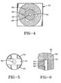
- the head 62 of the plunger 32 has a diameter which closely approximates that of the diameter of the fluid chamber in the portion in which the head 62 slidably moves. This helps to keep the plunger properly aligned as it slides back and forth. While a close fit provides for good guiding of the plunger, it does not provide a good flow path for the material. Therefore, in order to allow for the fluid material to flow past the head, bypass channels 64 are provided in the adapter body.
- Causing the fluid to flow past the plunger in this manner helps to prevent dead spots from occurring in the flow of the adhesive through the dispenser.
- the fluid may begin to solidify to produce undesirable particles or chunks, commonly know as char.
- the flow path through channels 22 and around the plunger head via channels 64 may result in excessive pressure drops across the plunger. In such instances, the pressure drop across the head of the plunger may be reduced by shunting some of the adhesive directly into the fluid chamber 20 from the outer annular groove 18 via channels 23.
- the face 70 of the head 62 of the plunger 32 When dispensing, the face 70 of the head 62 of the plunger 32 will be adjacent to and/or in contact with the end 52 of the fixed pole 50. Fluid material trapped between face 70 of the plunger head 62 and the end 52 of the fixed pole will contribute to an increase in the force required to begin to move the plunger to the closed position and/or will cause the closing response time to increase. This phenomenon is similar to the increase in force that is required to separate two pieces of glass which have a drop of fluid placed in between them. As used herein, this phenomenon will be referred to as squeeze film lubrication.
- a means for introducing a flow of fluid between the pole 50 and the plunger 32 to provide vacuum relief may be accomplished by providing the head 62 with fluid flow channels 66, 68.
- Flow channel 66 extends axially from the face 70, closest to the pole 50. Intersecting with this channel is a radially extending channel 68 which opens into the chamber 20.
- fluid will be directed into the openings of fluid channel 68, into fluid channel 66, and eventually into the area 74, which is formed between the fixed pole 50 and the plunger head 62, as well as between the raised portions 72.
- the introduction of fluid into area 74 from channels 66 and 68 reduces the vacuum like attraction force between the pole and the plunger as the plunger is being driven to the closed position.
- this flow path 66, 68 helps in decreasing the response time necessary to move the plunger to the open position.
- the plunger moves from the closed to the open position, there is fluid between the head 62 of the plunger and the fixed pole piece 50 which must be displaced.
- the head acting much like a piston will displace fluid through the bypass channels 64, as well as through flow channels 66 and 68, and into the fluid chamber 20.
- the amount of fluid which must be displaced is now the volume of fluid contained within the area 74.
- Fixed pole 50 may be provided with a bore 76. Contained within this bore is a non-magnetic material, such as 300 series stainless steel, brass, etc., which effectively prevents the adhesive from traveling into the interior of the fixed pole.
- the non-magnetic material within the bore 76 helps concentrate the magnetic flux generated by the coil on the pole face 52 of the pole 50 by reducing the cross-sectional area of the magnetic portion of the pole 50 which is perpendicular to the lines of flux.
- the coil assembly 42 may be retained within the assembly by a set screw 78.
- the windings of the coil 46 may be coupled to a source of electrical power by electrical conductors passing through a bore (not shown) to a respective electrical stud, such as illustrated at 80.
- Each of the studs 80 connect to female couplings 81 carried by an electrical connector 83.
- the female couplings 81 may be connected to the electrical conductors (not shown) of a cord set extending from port 82.
- the connector 83 may be retained to the coil housing by a screw 84.
- coil housing 44 may be provided with a plurality of fins 86 for dissipating the heat generated within the dispenser.
- the fins 86 of the heat sink 88 are thermally coupled to electromagnetic coil assembly 42.
- heat generated by the coil assembly 42 will be thermally transferred through the coil housing 44 and to the fins 86.
- the coil housing 44 directs heat away from the coil assembly 42, it is preferred that it is of a material that is fairly thermally conductive.
- coil housing 44 is also of a material which will help direct the field generated by the coil 46.
- the housing is of a magnetic material, such as a ferro-magnetic material.
- the heat sink and the housing 44 may be one piece, they could be two separate pieces.
- a dispenser has been built wherein good results have been obtained with aluminum heat sinks attached to the coil housing 44.
- FIG. 7 there is illustrated a graph of the temperature of the coil of an electric dispenser versus the power utilized by the coil.
- the electric dispenser according to an embodiment of the invention was equipped with detachable aluminum heat sinks. The temperature of the coil was monitored at various power levels both with and without the heat sinks attached to the housing of the dispenser. The application temperature of the adhesive during this experiment was 355°F while the ambient temperature was approximately 70°F. The temperature plotted on each curve is an average of all temperatures taken at that particular power level.
- the graph of the temperature without heat sinks is illustrated by line 90 while that of the temperature with heat sinks is illustrated by line 92.
- the temperature differential between the two lines becomes generally greater.
- the benefit of the heat sinks becomes more and more apparent. Being able to operate at higher power levels allows the coil to be driven open/closed faster, thereby allowing the dispenser to operate at faster cycle times.
- the plunger is a ferromagnetic material, such as steel, it is preferable to match the thermal expansion coefficient of the various parts which the plunger inter-reacts with, such as the body 12, seat, etc. Due to the heat fluid material and/or its associated heaters, these materials are going to expand. At higher application temperatures this expansion becomes greater. If aluminum is used, for the body, it will expand faster than that of the plunger. This may cause air gap variations. Therefore, it is preferred that the body 12 and the plunger 32 are made from the same materials or from materials which have the same or close coefficients of thermal expansions.
- the body 12 and the adapter body 16 out of stainless steel not only helps maintain the magnetic air gap at varying temperatures, but also allows for a more compact unit.
- hot melt adhesive dispensing systems can operate at relatively high pressures, such as for example, between 1000-1500 psi, the bodies 12 and 16 must be able to withstand such pressures.
- Bodies manufactured from aluminum would require greater cross-sectional areas than those manufactured from steel. As a result, a smaller and more compact unit may be produced by utilizing steel for the bodies 12 and 16.
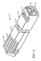
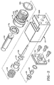
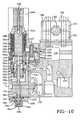
- the dispenser 10 a includes a dispenser body 12 a , having an inlet 14 a for receiving a source of fluid material, such as a hot melt adhesive.
- Inlet 14 a may be attached to a service module 100 or manifold having internal fluid passages 101 for supplying fluid.
- An O-ring 15 d is mounted within inlet port 14 a .
- the dispenser 10 a may be mounted to the service block by mounting screws 17 a .
- the adapter body 16 a is mounted within a cavity of the body 12 a .
- the adapter body 16 a has an outer annular groove 18 a , which is coupled to the inlet 14 a .
- the adapter body and the dispenser body form a fluid chamber 20 a .
- An O-ring 15 e may be used to provide a seal between the adapter and dispenser bodies 16 a , 12 a .
- fluid is transferred from the annular groove 18 a to the fluid chamber 20 a by fluid passageways 22 a and 23 a .
- the fluid chamber 20 a is coupled to the discharged outlet 24 a via an axially extending fluid passageway 26 a .
- a nozzle adapter 28 a Attached to the dispenser body 12 a is a nozzle adapter 28 a , which may be mounted to the dispenser body by screws 102 extending through openings 30 d .
- the outer periphery of the nozzle adapter 28 a may have threads 31 a for receiving a nozzle, not shown.
- a plunger 32 a Located within the fluid chamber 20 a and the fluid passageway 26 a is a plunger 32 a , which is slidably mounted for reciprocal motion and may be constructed as the plunger of 32 of Figures 1-6.
- a seat 36 a is located within the nozzle adapter 28 a , while an insert 38 a aligns the seat 36 a and the nozzle adapter 28 a with the fluid passageway 26 a in dispenser body 12 a .
- the insert 38 a may have point guide contacts, for guiding the plunger into the seat 36 a as the plunger 32 a moves from an open position to a closed position.
- the plunger 32 a is biased to the closed position by a spring 56 a .
- the electromagnetic coil assembly 42 a is enclosed by housing 44 a .
- the electromagnetic coil assembly generates an electromagnetic field when it is subjected to a source of electrical power.
- the electromagnetic coil assembly 42 a includes a coil 46 a comprising a plurality of windings wrapped around a bobbin or spool 104.
- the windings of the spool 104 may be provided with an outer wrapping of electrical tape 106, such as Nomex tape.
- the portion of the bobbin 104 closest to the plunger 32 a has an end piece 108 which extends radially outwardly.
- the portion 108 contains two electrical studs 110. These electrical studs 110 connect to the coil wire 112 forming the windings of the coil.
- the wire which forms the windings of the coil is attached at one end to one of the studs 110 and is attached at the other end to the other stud.
- the bobbin is also supplied with two electrical barriers 114 for isolating electrically the studs 110 from conductive members.
- a grounding connection, stud 116 is held captive in the housing 44 a , such as by a pin 118.
- Grounding stud 116 extends through the base 108 of the bobbin 104 when assembled to ground the housing 44 a .
- the electrical coil assembly 42 a may be encased in a potting layer, so as to affix the coil assembly 42 a to the housing 44 a .
- the potting material which preferably has a high thermal conductivity in order to transfer the heat generated by the coil to the housing 44 a , may be for example, an epoxy-based material.
- studs 110 are electrical conductors, to couple the coil to a source of electrical power while stud 118 is the grounding conductor.
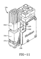
- the plug assembly 120 mates with a receptacle assembly 122 carried by the service block 100.
- the spool 104 of the electromagnetic coil assembly 42 a is located around a pole piece 50 a which is generally cylindrical in shape, having an end in fluid communication with the fluid chamber 20 a .
- a ring or spacer 54 a may be located about the periphery of and brazed to the pole piece 50 a to maintain the spacing between the pole piece and the adapter body 16 a and to provide a seal to prevent the flow of the fluid material from contacting the coil assembly.
- it is preferable that the spool 104 is spaced from the ring or spacer 54 a .
- an air gap 55 a between the ring 54 a and the spool 104 may be formed without requiring the raised annular portion 48 a that was required in the spool 48 of the first embodiment. Again, this spacing results in an air gap directly between the spool and the ring 54 a and directly between the spool and the fluid chamber. Thus additional insulation is provided over and above the function of the insulating portion of ring 54 a . Therefore, the windings of the coil 46 a are both physically and thermally isolated from the fluid material. Again, as an alternative to utilizing the air, other insulation may be used.
- heaters 124 within service module 100 are heaters 124, as well as a temperature sensor, such as an RTD, for controlling the operation of the heaters 124. Also, within service module 100 are electrical passageways 128 containing power and control wires (not shown), such as for coupling the electrical receptacle 122 to a source of electrical power in order to actuate or de-actuate the electromagnetic coil assembly 42 a , providing power to the heaters, etc.
- the service module 100 may also contain a thermal barrier 130 disposed between the heaters 124, and the fluid passageways 101 and the temperature sensor 126.
- This thermal barrier 130 may be an air passageway such that more heat is directed towards the dispenser body 12 a , as opposed to the temperature sensor 126.
- the function of the thermal barrier 130 may be more fully described as set forth in U.S. patent application 08/235,096 filed on April 29, 1994, which is owned by the Assignee of this invention, and in which the disclosure thereof is incorporated herein by reference.
- the service module or adhesive manifold 100 may include a mounting block 132 attached to the service block 100 by screws 134.
- the mounting block 132 may be formed in two half sections 136, 138 which receive a mounting bar 140 therebetween.
- the bolts 134 when screwed in tighten down against a bar 140 to secure the mounting block 138 and in turn the manifold or service block 100 thereto.
- the dispenser 10 a is mounted to the service block 100 via screws 17 a and electrically connected via plug 120 and receptacle 122 of the block 100.
- the coil assembly 42 a may be serviced or replaced without removing the dispenser body 12 a from the block 100.
- the coil housing 44 a is attached via bolt 142 which mates with the pole 50 a .
- Unscrewing bolt 142 allows the coil housing 44 a to be slid off of the dispenser assembly.
- the coil housing 44 a and the coil assembly 42 a have been removed from the dispenser revealing pole piece 50 a , while the body 12 a remains attached to the service block and in turn remains connected to the source of adhesive fluid.
- the coil assembly would remain within the coil housing.
- the old coil assembly may be replaced and the old housing reattached or a new assembly, including a new coil housing having a new coil already potted therein, may be then installed. This provides a quick means of changing the coil assembly. Only one bolt is required to be removed and the adhesive connections do not need to be disconnected.
- coil housing 44 of Figure 3 may be slid off after unscrewing screw 78 and disconnecting the cord set from the electrical connector. This in turn would allow removal of the coil assembly as well as leaving pole piece 50 exposed while body 12 remains attached to a service block or other mounting device containing a source of fluid. Again, this design provides a quick means of changing and/or inspecting a coil assembly without disconnecting the dispenser 10 from the source of pressurized fluid because the flow of adhesive is not through the center of the pole piece 50 as in previous designs.
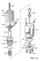
- a shim plate 150 is utilized during the assembly of the dispenser which has the same thickness as the desired air gap.
- seat 36 a , insert 38 a , and O-ring 101 are assembled inside of nozzle adapter 28 a .
- This assembly is then bolted to the dispenser body 12 a by screws 102.
- the pole/adapter assembly 152 which includes pole 50 a , ring 54 a , adapter body 16 a and O-ring 15 e , is inverted and plunger 32 a and spring 56 a are located within the cavity of the adapter body 16 a .
- This assembly is then inserted into the dispenser body 12 a and is screwed in until the plunger is fully seated.
- Locking screw 144 is then backed out of the dispenser body 12 a until it contacts the tapered edge 146 of the adapter body 16 a .
- a screw 143 extends into the dispenser body 12 a , and into the cavity containing O-ring 15 e to prevent the pole/adapter assembly 152 from being removed without first removing the screw 143.
- the nozzle adapter 28 a is then removed from the dispenser body 12 a by removing screws 102.
- Gauge plate 150 is installed between the nozzle adapter 28 a and the dispenser body 12 a .
- the nozzle adapter and the gauge plate are now attached to the dispenser body 12 a by the four bolts 102. Since the assembly had been tightened before until the plunger was firmly seated against the seat 36 a , the plunger 32 a will now be spaced from the pole 50 a by the thickness of the shim plate 150.
- the material hardness of the screw 144 is harder than that of the tapered shoulder 146 of the adapter body 16 a .
- the force applied to the screw 144 when it is caused to be drawn in contact with the adapter body shoulder 146 should be such that a small dent is formed in the shoulder 146.
- the formation of this small dent in the tapered shoulder 146 of the adapter body, combined with the opposing axial forces applied to both the adapter body's threads 154 and those of the locking screw 144, provide anti-rotational forces significantly greater than those that should be encountered during assembly or service. This also helps so that the impact forces applied by plunger 32 a against pole piece 50 a cannot disturb or tend to loosen the locking adjustment position.
- the direction of rotation of the locking screw 144 during tightening is preferably counter-clockwise, which tends to rotate the adapter body 16 a clockwise, which provides a firm contact between the end of the pole 52 a and the head of the plunger 32 a such that the final air gap matches the thickness of the shim plate 150.
- coil housing 44 a may be provided with a plurality of fins 86 a for dissipating the heat generated within the dispenser.
- the fins 86 a of the heat sink 88 a are thermally coupled to electromagnetic coil assembly 42 a .
- heat will be transferred through the coil housing 44 and to the fins 86 a as in the previous embodiment.
- the magnitude of the current passing through the coil may be reduced to a lower hold in current as set forth previously.
Landscapes
- Engineering & Computer Science (AREA)
- Mechanical Engineering (AREA)
- Coating Apparatus (AREA)
Applications Claiming Priority (2)
| Application Number | Priority Date | Filing Date | Title |
|---|---|---|---|
| US331906 | 1989-03-31 | ||
| US08/331,906 US5535919A (en) | 1993-10-27 | 1994-10-31 | Apparatus for dispensing heated fluid materials |
Publications (2)
| Publication Number | Publication Date |
|---|---|
| EP0711943A2 true EP0711943A2 (de) | 1996-05-15 |
| EP0711943A3 EP0711943A3 (de) | 1997-03-12 |
Family
ID=23295869
Family Applications (1)
| Application Number | Title | Priority Date | Filing Date |
|---|---|---|---|
| EP95115911A Withdrawn EP0711943A3 (de) | 1994-10-31 | 1995-10-10 | Vorrichtung zum Ausgeben heissen flüssigen Materials |
Country Status (6)
| Country | Link |
|---|---|
| US (1) | US5535919A (de) |
| EP (1) | EP0711943A3 (de) |
| JP (1) | JPH08206562A (de) |
| KR (1) | KR960013979A (de) |
| AU (1) | AU3454995A (de) |
| CA (1) | CA2159761A1 (de) |
Cited By (3)
| Publication number | Priority date | Publication date | Assignee | Title |
|---|---|---|---|---|
| EP1949977A1 (de) * | 2007-01-25 | 2008-07-30 | Nordson Corporation | Vorrichtung zum Abgeben von flüssigem Material |
| WO2013188698A1 (en) * | 2012-06-15 | 2013-12-19 | Illinois Tool Works Inc. | Hot melt adhesive dispensing system including adhesive cut-off module |
| EP2523893A4 (de) * | 2010-01-14 | 2014-03-19 | Nordson Corp | Vorrichtung und verfahren zum sprühen eines flüssigmaterials in gewünschten mustern |
Families Citing this family (57)
| Publication number | Priority date | Publication date | Assignee | Title |
|---|---|---|---|---|
| US5915591A (en) * | 1997-09-10 | 1999-06-29 | Illinois Tool Works Inc. | Electric solenoid valve for hot melt adhesive and method therefor |
| US5875922A (en) * | 1997-10-10 | 1999-03-02 | Nordson Corporation | Apparatus for dispensing an adhesive |
| US5934520A (en) * | 1997-11-03 | 1999-08-10 | Nordson Corporation | Liquid dispensing device |
| US6152386A (en) * | 1998-11-06 | 2000-11-28 | Nordson Corporation | Handgun and hose assembly for dispensing liquids |
| US6511301B1 (en) | 1999-11-08 | 2003-01-28 | Jeffrey Fugere | Fluid pump and cartridge |
| US7207498B1 (en) | 2000-01-26 | 2007-04-24 | Dl Technology, Llc | Fluid dispense tips |
| US6957783B1 (en) | 1999-01-26 | 2005-10-25 | Dl Technology Llc | Dispense tip with vented outlets |
| US6343721B1 (en) * | 1999-05-26 | 2002-02-05 | Loctite Corporation | Sealed dispensing device |
| US6981664B1 (en) | 2000-01-26 | 2006-01-03 | Dl Technology Llc | Fluid dispense tips |
| US6892959B1 (en) * | 2000-01-26 | 2005-05-17 | Dl Technology Llc | System and method for control of fluid dispense pump |
| US6305583B1 (en) * | 2000-02-11 | 2001-10-23 | Tlx Technologies | Valve for viscous fluid applicator |
| US6401976B1 (en) | 2000-03-23 | 2002-06-11 | Nordson Corporation | Electrically operated viscous fluid dispensing apparatus and method |
| US7289878B1 (en) * | 2000-05-15 | 2007-10-30 | Nordson Corporation | Apparatus and method for modifying operation of an electric gun driver |
| US6761290B2 (en) * | 2000-05-16 | 2004-07-13 | Nordson Corporation | Device for applying fluid material on a substrate, and application valve |
| US6669057B2 (en) * | 2001-10-31 | 2003-12-30 | Nordson Corporation | High-speed liquid dispensing modules |
| KR100505180B1 (ko) * | 2002-02-20 | 2005-08-01 | 엘지.필립스 엘시디 주식회사 | 노즐세정장치를 구비한 액정적하장치 및 액정적하방법 |
| US6983867B1 (en) | 2002-04-29 | 2006-01-10 | Dl Technology Llc | Fluid dispense pump with drip prevention mechanism and method for controlling same |
| US6874708B2 (en) * | 2003-02-13 | 2005-04-05 | Illinois Tool Works Inc. | Automatic air-assisted manifold mounted gun |
| US7331482B1 (en) | 2003-03-28 | 2008-02-19 | Dl Technology, Llc | Dispense pump with heated pump housing and heated material reservoir |
| US6994234B2 (en) * | 2003-04-03 | 2006-02-07 | Nordson Corporation | Electrically-operated dispensing module |
| WO2004094070A1 (en) * | 2003-04-15 | 2004-11-04 | Nordson Corporation | Liquid spray gun |
| US7178704B2 (en) * | 2004-04-15 | 2007-02-20 | Nordson Corporation | Electrically-operated dispenser |
| US7296707B2 (en) * | 2004-06-10 | 2007-11-20 | Graco Minnesota Inc. | Method and apparatus for dispensing a hot-melt adhesive |
| US20060065868A1 (en) * | 2004-09-28 | 2006-03-30 | Strong Warren N | Diaphragm valve |
| US7214885B2 (en) * | 2004-09-29 | 2007-05-08 | Nordson Corporation | Liquid dispensing system having a modular cord set |
| US7617955B2 (en) * | 2004-10-28 | 2009-11-17 | Nordson Corporation | Method and system for dispensing liquid from a module having a flexible bellows seal |
| US7296714B2 (en) * | 2004-11-22 | 2007-11-20 | Nordson Corporation | Device for dispensing a heated liquid having a flexible hydraulic seal |
| DE102004058542A1 (de) * | 2004-12-03 | 2006-06-08 | Nordson Corporation, Westlake | Rotationsauftragskopf und Etikettieranlage zum Aufbringen von Etiketten |
| US7414532B2 (en) * | 2005-04-20 | 2008-08-19 | Nordson Corporation | Method of attaching RFID tags to substrates |
| FR2887951A1 (fr) * | 2005-05-02 | 2007-01-05 | Valco Cincinnati Inc | Soupape a commande par solenoøde, distributeur d'adhesif et procede de distribution |
| US7771556B2 (en) * | 2005-07-01 | 2010-08-10 | Nordson Corporation | Apparatus and process to apply adhesive during labeling operations |
| US20090124996A1 (en) * | 2006-11-03 | 2009-05-14 | Scott Heneveld | Apparatus and methods for injecting high viscosity dermal fillers |
| US8061564B2 (en) * | 2006-11-15 | 2011-11-22 | Nordson Corporation | Liquid dispensing apparatus including an attachment member |
| US8474660B2 (en) * | 2006-11-15 | 2013-07-02 | Nordson Corporation | Dispensing apparatus having a pivot actuator |
| US8707559B1 (en) | 2007-02-20 | 2014-04-29 | Dl Technology, Llc | Material dispense tips and methods for manufacturing the same |
| JP2010022881A (ja) * | 2007-03-30 | 2010-02-04 | Musashi Eng Co Ltd | 液材吐出装置および液材吐出方法 |
| EP2002898A1 (de) * | 2007-06-14 | 2008-12-17 | J. Zimmer Maschinenbau Gesellschaft m.b.H. | Auftragungseinrichtung zum Auftragen von Fluid auf ein Substrat mit Ventileinrichtungen, Verfahren zum Reinigen des Auftragungseinrichtung und Ventileinrichtung für die Auftragungseinrichtung |
| DE102007029064A1 (de) * | 2007-06-21 | 2008-12-24 | Focke & Co.(Gmbh & Co. Kg) | Ventil, insbesondere Leimventil |
| DE102009015231A1 (de) * | 2009-04-01 | 2010-10-07 | Focke & Co.(Gmbh & Co. Kg) | (Leim-)Ventil |
| US8864055B2 (en) * | 2009-05-01 | 2014-10-21 | Dl Technology, Llc | Material dispense tips and methods for forming the same |
| US8333307B2 (en) * | 2009-10-06 | 2012-12-18 | Nordson Corporation | Liquid dispensing module |
| CN103502781B (zh) * | 2009-12-08 | 2016-08-24 | 诺信公司 | 力放大驱动系统,喷射分配器,以及分配流体的方法 |
| ES2647863T3 (es) * | 2010-01-14 | 2017-12-27 | Nordson Corporation | Aplicación a chorro de volúmenes específicos de líquido de alta viscosidad |
| ES2530260T3 (es) * | 2010-10-29 | 2015-02-27 | Gruppo Cimbali S.P.A. | Pieza terminal reemplazable para una lanza de vapor de una máquina de café |
| US8794491B2 (en) * | 2011-10-28 | 2014-08-05 | Nordson Corporation | Dispensing module and method of dispensing with a pneumatic actuator |
| US9725225B1 (en) | 2012-02-24 | 2017-08-08 | Dl Technology, Llc | Micro-volume dispense pump systems and methods |
| US9377114B2 (en) | 2012-04-25 | 2016-06-28 | Nordson Corporation | Pressure control valve for reactive adhesives |
| US9328841B2 (en) * | 2013-09-17 | 2016-05-03 | Nordson Corporation | Fluid dispenser utilizing dual coils and methods of fluid dispensing |
| DE102014007048A1 (de) * | 2014-05-14 | 2015-11-19 | Eisenmann Ag | Beschichtungssystem zum Beschichten von Gegenständen |
| JP1520692S (de) * | 2014-06-30 | 2015-04-06 | ||
| US10072768B1 (en) * | 2015-06-18 | 2018-09-11 | Jansen's Aircraft Controls Systems, Inc. | Thermo-stratified, passive-cooled servo valve |
| US10088075B2 (en) | 2015-08-20 | 2018-10-02 | Ok International Inc. | Disposable diaphragm valve |
| US10471461B2 (en) * | 2017-03-01 | 2019-11-12 | Nordson Corporation | Liquid dispensing module |
| IT201700067828A1 (it) * | 2017-06-19 | 2018-12-19 | Kromia S R L | Macchina di smaltatura per supporti ceramici. |
| KR102392753B1 (ko) * | 2017-09-25 | 2022-05-03 | 주식회사 만도 | 브레이크 시스템용 솔레노이드 밸브 |
| US10933435B2 (en) * | 2017-12-21 | 2021-03-02 | The Boeing Company | Apparatuses for depositing an extrudable substance onto a surface |
| US11746656B1 (en) | 2019-05-13 | 2023-09-05 | DL Technology, LLC. | Micro-volume dispense pump systems and methods |
Citations (1)
| Publication number | Priority date | Publication date | Assignee | Title |
|---|---|---|---|---|
| US4951917A (en) | 1989-12-06 | 1990-08-28 | Slautterback Corporation | Dynamic response time for electromagnetic valving |
Family Cites Families (56)
| Publication number | Priority date | Publication date | Assignee | Title |
|---|---|---|---|---|
| US1504773A (en) * | 1922-03-31 | 1924-08-12 | Marston Sheldon | Electromagnetic valve |
| US2114961A (en) * | 1934-08-20 | 1938-04-19 | Honeywell Regulator Co | Electromagnetic valve |
| DE936671C (de) * | 1951-08-12 | 1955-12-15 | Siemens Ag | Einrichtung an einer Duese zur elektrostatischen Oberflaechenbehandlung |
| US2860850A (en) * | 1953-05-25 | 1958-11-18 | Garrett Corp | Solenoid valve |
| US3212715A (en) * | 1963-06-19 | 1965-10-19 | Eric H Cocks | Solenoid airless spray gun |
| US3250293A (en) * | 1963-10-17 | 1966-05-10 | American Brake Shoe Co | Electric and fluid pressure operated valve mechanism |
| US3329347A (en) * | 1965-10-19 | 1967-07-04 | Vitramon Inc | Valved liquid ejector capable of emitting intermittent spurts |
| US3412971A (en) * | 1966-03-03 | 1968-11-26 | Armstrong Cork Co | Electrically-controlled valve apparatus and control circuit suitable for use therein |
| DE1272666B (de) * | 1966-11-08 | 1968-07-11 | Teldix Luftfahrt Ausruestung | Elektromagnetisch betaetigbares Ventil mit Tauchankermagnetsystem |
| US3408008A (en) * | 1966-12-02 | 1968-10-29 | Eric H. Cocks | Apparatus for applying hot melt adhesives |
| US3422850A (en) * | 1966-12-15 | 1969-01-21 | Ranco Inc | Electromagnetic fluid valve |
| US3463363A (en) * | 1967-10-12 | 1969-08-26 | Fusion Inc | Applicator gun |
| US3531080A (en) * | 1968-05-07 | 1970-09-29 | Abex Corp | Control valve |
| US3485417A (en) * | 1968-06-19 | 1969-12-23 | Eric H Cocks | Hand-held applicator for hot-melt adhesives |
| US3593241A (en) * | 1969-07-18 | 1971-07-13 | Alfred J Ludwig | Solenoid valve having a slotted flux sleeve for nesting the winding leads |
| FR2079805A5 (de) * | 1970-02-13 | 1971-11-12 | Roto Diesel Sa | |
| US3670274A (en) * | 1970-10-06 | 1972-06-13 | Skinner Precision Ind Inc | Explosion-proof valve operator |
| DE2062420A1 (de) * | 1970-12-18 | 1972-06-22 | Bosch Gmbh Robert | Elektromagnetisch betätigbares Kraftstoff-Einspritzventil für eine Brennkraftmaschine |
| US3704833A (en) * | 1971-02-17 | 1972-12-05 | Fred O Wheat | Solenoid valve assembly |
| DE2110596B2 (de) * | 1971-03-05 | 1978-10-05 | Robert Bosch Gmbh, 7000 Stuttgart | Magnetventil |
| DE2161605A1 (de) * | 1971-12-11 | 1973-06-14 | Linde Ag | Magnetventil |
| DE2222448A1 (de) * | 1972-05-08 | 1973-11-22 | Teves Gmbh Alfred | Elektromagnetisches ventil |
| US3936030A (en) * | 1972-05-08 | 1976-02-03 | Itt Industries, Inc. | Electromagnetic valve |
| US3827604A (en) * | 1972-09-11 | 1974-08-06 | Nordson Corp | Modular solenoid-operated dispenser |
| US3811601A (en) * | 1972-09-11 | 1974-05-21 | Nordson Corp | Modular solenoid-operated dispenser |
| FR2207435A5 (de) * | 1972-11-17 | 1974-06-14 | Wittenberge Gulliez Juli | |
| US3965377A (en) * | 1973-06-21 | 1976-06-22 | Carbonneau Industries, Inc. | Linear force generator |
| US3921670A (en) * | 1974-07-01 | 1975-11-25 | Clippard Instr Lab Inc | Magnetically operated valve with spider armature |
| DE2458728A1 (de) * | 1974-12-12 | 1976-06-24 | Bosch Gmbh Robert | Elektromagnetisch betaetigbares einspritzventil |
| US4044324A (en) * | 1976-04-30 | 1977-08-23 | Ledex, Inc. | Coil compressed plunger cavity components for a wet type solenoid |
| US4218669A (en) * | 1978-09-13 | 1980-08-19 | SR Engineering | Adjustable short stroke solenoid |
| US4295631A (en) * | 1980-03-21 | 1981-10-20 | Allen Walter E | Solenoid operated valve |
| ATE17883T1 (de) * | 1981-04-29 | 1986-02-15 | Solex Uk Ltd | Eine elektromagnetische f luessigkeitseinspritzvorrichtung und ein einzelpunktkraftstoffeinspritzsystem fuer eine verbrennungskraftmaschine. |
| US4453652A (en) * | 1981-09-16 | 1984-06-12 | Nordson Corporation | Controlled current solenoid driver circuit |
| US4488665A (en) * | 1982-05-24 | 1984-12-18 | Spraymation, Inc. | Multiple-outlet adhesive applicator apparatus and method |
| US4437488A (en) * | 1982-05-24 | 1984-03-20 | Lockwood Technical Inc. | Solenoid valve for hot melt material |
| JPS6014678A (ja) * | 1983-07-04 | 1985-01-25 | Taiheiyo Kogyo Kk | 電磁弁 |
| US4981281A (en) * | 1983-12-21 | 1991-01-01 | Robert W. Brundage | Solenoid controlled fluid flow valve |
| DE3604436A1 (de) * | 1986-02-13 | 1987-08-20 | Bosch Gmbh Robert | Elektromagnet fuer kraftstoffeinspritzanlagen |
| DE3641470A1 (de) * | 1986-12-04 | 1988-06-16 | Bosch Gmbh Robert | Elektromagnetisch betaetigbares kraftstoffeinspritzventil |
| US5022629A (en) * | 1988-01-04 | 1991-06-11 | Interface, Inc. | Valve construction |
| US4969602A (en) * | 1988-11-07 | 1990-11-13 | Nordson Corporation | Nozzle attachment for an adhesive dispensing device |
| US4981280A (en) * | 1989-04-27 | 1991-01-01 | The Aro Corporation | Solenoid actuated fluid valve |
| US4962871A (en) * | 1989-07-24 | 1990-10-16 | Valco Cincinnati, Inc. | Applicator utilizing high speed non-contact extrusion valve |
| DE3930785C1 (de) * | 1989-09-14 | 1991-03-07 | Danfoss A/S, Nordborg, Dk | |
| US5027976A (en) * | 1989-10-10 | 1991-07-02 | Nordson Corporation | Multi-orifice T-bar nozzle |
| US5010911A (en) * | 1989-12-15 | 1991-04-30 | Wormald U.S., Inc. | Electromagnetic valve operator |
| JP2518031Y2 (ja) * | 1990-12-19 | 1996-11-20 | 株式会社ユニシアジェックス | 燃料噴射弁 |
| US5207352A (en) * | 1991-04-19 | 1993-05-04 | Nordson Corporation | Method and apparatus for dispensing high viscosity fluid materials |
| US5192936A (en) * | 1991-08-22 | 1993-03-09 | Mac Valves, Inc. | Solenoid |
| US5294057A (en) * | 1992-04-21 | 1994-03-15 | Spraying Systems Co. | Solenoid operated liquid spray gun |
| US5405050A (en) * | 1993-10-27 | 1995-04-11 | Nordson Corporation | Electric dispenser |
| US5375738A (en) * | 1993-10-27 | 1994-12-27 | Nordson Corporation | Apparatus for dispensing heated fluid materials |
| USD354295S (en) | 1993-11-08 | 1995-01-10 | Nordson Corporation | Fluid dispensing module for dispensing heated fluids, such as hot melt adhesive |
| USD354296S (en) | 1993-11-08 | 1995-01-10 | Nordson Corporation | Fluid dispensing module for dispensing heated fluids, such as hot melt adhesive |
| US5407101A (en) * | 1994-04-29 | 1995-04-18 | Nordson Corporation | Thermal barrier for hot glue adhesive dispenser |
-
1994
- 1994-10-31 US US08/331,906 patent/US5535919A/en not_active Expired - Fee Related
-
1995
- 1995-10-03 CA CA002159761A patent/CA2159761A1/en not_active Abandoned
- 1995-10-10 EP EP95115911A patent/EP0711943A3/de not_active Withdrawn
- 1995-10-30 KR KR1019950037953A patent/KR960013979A/ko not_active Withdrawn
- 1995-10-30 AU AU34549/95A patent/AU3454995A/en not_active Abandoned
- 1995-10-31 JP JP7282913A patent/JPH08206562A/ja not_active Withdrawn
Patent Citations (1)
| Publication number | Priority date | Publication date | Assignee | Title |
|---|---|---|---|---|
| US4951917A (en) | 1989-12-06 | 1990-08-28 | Slautterback Corporation | Dynamic response time for electromagnetic valving |
Cited By (5)
| Publication number | Priority date | Publication date | Assignee | Title |
|---|---|---|---|---|
| EP1949977A1 (de) * | 2007-01-25 | 2008-07-30 | Nordson Corporation | Vorrichtung zum Abgeben von flüssigem Material |
| US8070077B2 (en) | 2007-01-25 | 2011-12-06 | Nordson Corporation | Apparatus for dispensing liquid material |
| EP2523893A4 (de) * | 2010-01-14 | 2014-03-19 | Nordson Corp | Vorrichtung und verfahren zum sprühen eines flüssigmaterials in gewünschten mustern |
| WO2013188698A1 (en) * | 2012-06-15 | 2013-12-19 | Illinois Tool Works Inc. | Hot melt adhesive dispensing system including adhesive cut-off module |
| US9126751B2 (en) | 2012-06-15 | 2015-09-08 | Illinois Tool Works Inc. | Hot melt adhesive dispensing system including adhesive cut-off module |
Also Published As
| Publication number | Publication date |
|---|---|
| KR960013979A (ko) | 1996-05-22 |
| AU3454995A (en) | 1996-05-16 |
| US5535919A (en) | 1996-07-16 |
| JPH08206562A (ja) | 1996-08-13 |
| EP0711943A3 (de) | 1997-03-12 |
| CA2159761A1 (en) | 1996-05-01 |
Similar Documents
| Publication | Publication Date | Title |
|---|---|---|
| US5535919A (en) | Apparatus for dispensing heated fluid materials | |
| US5375738A (en) | Apparatus for dispensing heated fluid materials | |
| US5405050A (en) | Electric dispenser | |
| EP0908240B1 (de) | Abgabevorrichtung für Klebstoffe | |
| EP1181106B1 (de) | Flüssigkeitsabgabegerät für viskose flüssigkeiten | |
| EP3153693B1 (de) | Kraftstoffeinspritzventil | |
| CA2459317A1 (en) | Infusion device and driving mechanism for same | |
| EP1196707B1 (de) | Hochdruckelektromagnetvorgesteuertes ventil | |
| EP1241359A1 (de) | Ventile mit Schwingspulenmotor und Wärmeableitung | |
| AU600101B2 (en) | Pilot operated coolant control valves in manifold assembly | |
| JPH11210920A (ja) | 流体制御弁 | |
| SE470025B (sv) | Elektriskt manövrerad ventil och sätt för sammansättning därav | |
| US20060243758A1 (en) | Solenoid-operated fluid valve and assembly incorporating same | |
| CN102762904B (zh) | 用于安装在安装块中的可电磁切换的阀 | |
| GB2485440A (en) | A seal assembly for a metering valve | |
| EP1169135A1 (de) | Elektrisch betätigte ausgabevorrichtung für flüssigkeiten und verfahren zur ausgabe von viskosen flüssigkeiten | |
| JP4022633B2 (ja) | 電磁弁 | |
| EP1251302A2 (de) | Einrichtung zur Abgabe einer zähen Flüssigkeit | |
| JP2005061443A (ja) | 電磁式比例弁 | |
| CN102466075B (zh) | 用于计量阀的密封组件 | |
| CN117869646A (zh) | 一种航天器用卸荷式用永磁自锁电磁阀 | |
| HK1262505A1 (en) | Diaphragm valve | |
| TW201643334A (zh) | 電磁閥裝置 |
Legal Events
| Date | Code | Title | Description |
|---|---|---|---|
| PUAI | Public reference made under article 153(3) epc to a published international application that has entered the european phase |
Free format text: ORIGINAL CODE: 0009012 |
|
| AK | Designated contracting states |
Kind code of ref document: A2 Designated state(s): CH DE ES FR GB IT LI |
|
| PUAL | Search report despatched |
Free format text: ORIGINAL CODE: 0009013 |
|
| AK | Designated contracting states |
Kind code of ref document: A3 Designated state(s): CH DE ES FR GB IT LI |
|
| STAA | Information on the status of an ep patent application or granted ep patent |
Free format text: STATUS: THE APPLICATION IS DEEMED TO BE WITHDRAWN |
|
| 18D | Application deemed to be withdrawn |
Effective date: 19970913 |