EP0712018B1 - Kassette zur Unterbringung und zum Schutz einer optischen Faser und Anordnung zur Lagerung von optischen Fasern - Google Patents
Kassette zur Unterbringung und zum Schutz einer optischen Faser und Anordnung zur Lagerung von optischen Fasern Download PDFInfo
- Publication number
- EP0712018B1 EP0712018B1 EP95402473A EP95402473A EP0712018B1 EP 0712018 B1 EP0712018 B1 EP 0712018B1 EP 95402473 A EP95402473 A EP 95402473A EP 95402473 A EP95402473 A EP 95402473A EP 0712018 B1 EP0712018 B1 EP 0712018B1
- Authority
- EP
- European Patent Office
- Prior art keywords
- casing
- cassette
- fibre
- core
- cassette according
- Prior art date
- Legal status (The legal status is an assumption and is not a legal conclusion. Google has not performed a legal analysis and makes no representation as to the accuracy of the status listed.)
- Expired - Lifetime
Links
Images

Classifications
-
- G—PHYSICS
- G02—OPTICS
- G02B—OPTICAL ELEMENTS, SYSTEMS OR APPARATUS
- G02B6/00—Light guides; Structural details of arrangements comprising light guides and other optical elements, e.g. couplings
- G02B6/44—Mechanical structures for providing tensile strength and external protection for fibres, e.g. optical transmission cables
- G02B6/4439—Auxiliary devices
- G02B6/4457—Bobbins; Reels
-
- G—PHYSICS
- G02—OPTICS
- G02B—OPTICAL ELEMENTS, SYSTEMS OR APPARATUS
- G02B6/00—Light guides; Structural details of arrangements comprising light guides and other optical elements, e.g. couplings
- G02B6/44—Mechanical structures for providing tensile strength and external protection for fibres, e.g. optical transmission cables
- G02B6/4439—Auxiliary devices
- G02B6/444—Systems or boxes with surplus lengths
- G02B6/4452—Distribution frames
- G02B6/44526—Panels or rackmounts covering a whole width of the frame or rack
-
- G—PHYSICS
- G02—OPTICS
- G02B—OPTICAL ELEMENTS, SYSTEMS OR APPARATUS
- G02B6/00—Light guides; Structural details of arrangements comprising light guides and other optical elements, e.g. couplings
- G02B6/44—Mechanical structures for providing tensile strength and external protection for fibres, e.g. optical transmission cables
- G02B6/4439—Auxiliary devices
- G02B6/444—Systems or boxes with surplus lengths
- G02B6/4453—Cassettes
-
- G—PHYSICS
- G02—OPTICS
- G02B—OPTICAL ELEMENTS, SYSTEMS OR APPARATUS
- G02B6/00—Light guides; Structural details of arrangements comprising light guides and other optical elements, e.g. couplings
- G02B6/44—Mechanical structures for providing tensile strength and external protection for fibres, e.g. optical transmission cables
- G02B6/4439—Auxiliary devices
- G02B6/444—Systems or boxes with surplus lengths
- G02B6/4453—Cassettes
- G02B6/4455—Cassettes characterised by the way of extraction or insertion of the cassette in the distribution frame, e.g. pivoting, sliding, rotating or gliding
Definitions
- the present invention relates to a cassette designed to allow individual accommodation and protection of the end of a single optical fiber sheathed, so as to authorize in particular the delivery of sufficient length of this fiber outside of this cassette to realize, at the end of the part of the fiber thus extracted from the cassette its connection with the end of another optical fiber sheathed by its own end, or on a bare part of this one, or even with a device of use, without introduce tensile or bending stresses on these fibers, such as these can in particular be damaged.
- fiber optics is taken here in a general sense and denotes as well as a single fiber, coated on the outside with a protective sheath, that a unitary tape formed by the association of a limited number of such fibers sheathed, arranged side by side and embedded in a common external coating ensuring the cohesion of this ribbon.
- a single fiber sheathed it is even more necessary to be able to have an appropriate extra length to be able to extract ribbon any of the associated fibers which constitute, in order to achieve the bond of this fiber with another as specified above.
- optical fibers these generally occur in the form of a very thin element, of great length but of extremely small diameter, of the order in particular 125 micrometers, covered with a sheath passing its diameter around 250 micrometers.
- Such fibers are therefore fragile and in particular should not be bending stresses with a radius in principle less than 37.5 mm, i.e. a diameter of 75 mm, at least according to the standards currently in force.
- this cassette must also be able to accommodate the splice made at the end of the fiber, which has a generally not negligible extra thickness.
- the fiber optic cables have a high number of such fibers, sometimes arranged in multiple ribbons and arranged contiguously to each other. It is therefore essential that the storage of all of these fibers is such that it allows to extract one exactly chosen, without disturbing others and in particular without risking injury or even breaking one or several of its neighbors, especially during the draw for the extra length required and its replacement, with or without the splice made at its end.
- these boxes do not generally allow accommodate the splices due to their extra thickness, forcing them to be fixed with an adhesive on the outside of the corresponding housing, which leads to increased risk deterioration during the next operation of connection with another fiber extracted from the housing, this without disturbing the bundle which constitutes the cable.
- the fibers are wound on a central core, integral with the housing where lodge these fibers, and whose presence at the center of the internal chamber in this box allows each fiber to not not exceed the aforementioned minimum curvature threshold.
- Gold when we pull on the end of a fiber to extract the desired extra length, the fiber wraps around the fixed core, producing a capstan effect which quickly causes it to block and break almost certain, if the tractive effort to extract it is for follow-up.
- US patents 5,263,585 and EP 0 185,923 illustrate examples of such embodiments.
- the invention relates to a cassette for storing and protection which avoids these disadvantages.
- the cassette considered, for housing and individual protection of a terminal portion of a single optical fiber or a unitary ribbon formed by a association of such fibers comprising a flat casing having a bottom provided at its periphery with a rim and at least one entry and at least one exit for said end portion of fiber or ribbon, the interior of said flat case containing in its center a cylindrical core projecting from the bottom of the housing so as to delimit, between the outer surface of said core and the bottom and the peripheral edge of the housing, an annular housing for the storage of said terminal portion of fiber or tape, which is intended to be wound freely around said cylindrical core according to a number of turns sufficient to provide outside of the housing a desired extra length following a pull exerted on its end outside said housing, is characterized in that said core cylindrical is mounted rotating on the bottom of the case, around a central pivot perpendicular to said bottom, and said bottom of the housing has a hollow counterbore in which penetrates the underside of the rotating core with limited lateral play, especially less than half
- the upper face of the rotating core is secured to a flat flange, parallel to the bottom of the housing and partially sealing from above the circular housing for receiving the fiber.
- the peripheral rim outer of the housing has a flat annular cover, directed towards the central pivot of the rotating core, substantially in the plane of the flange and delimiting with the side of it sufficient clearance to allow the passage of the fiber.
- the housing has a square cross section or rectangular, the annular cover being formed of four separate elements, each of which is arranged along one of the respective four sides of the case, each cover element being produced by means of a flexible plastic tongue, advantageously transparent, with a circular outer edge directed towards the center of the case and extending substantially parallel to the side of the flange carried by the rotating core.
- the edge device of the housing comprises, in each of the four angles thereof, an entry and / or exit passage fiber housed in this housing, these passages being arranged two by two along the diagonals of the housing.
- connection portions of each passage with the circular receiving housing of the fiber inside the housing have a profile rounded, so as not to damage the fiber which engages in this passage.
- this includes, outside the housing circular reception, along its lateral sides, of notches open to the outside, for fixing or the suspension of the housing.
- these notches have a contour in omega with a narrow part towards the outside, connected to a part which is substantially circular inwards.
- each passage in a corner of the housing has a recess median, substantially circular, for mounting a fixing member of the outer sheath of the fiber.
- this fixing member consists of two circular flat washers, tightening the flat sheath on plan and held against each other by screws or the like.
- the reception housing comprises, in a first variant, inside the housing and against the internal face of the peripheral rim thereof, at least one elongated rectilinear zone for placing place of this splice, inserted in the housing under the flexible tongue forming the corresponding element of the lid.
- the tab on the cover has legs projecting inward from the housing circular reception, to immobilize the splice of connection against the straight area, which is provided on the internal face of this housing, inside of the case.
- the splice is attached to the core cylindrical rotating, in the vicinity of the housing reception.
- the invention also relates to an installation for storage of optical fibers or formed unit ribbons by a combination of such fibers, comprising a plurality of cassettes of the aforementioned genre, as well as a device for storing or supporting said cassettes, which is characterized in that it comprises at least one rod to support these cassettes, which crosses the notches counterparts of their respective boxes in order to join together plan by plan, without hindering the possibility of switching any of these around this support rod.
- the support rod has a flat to lock the cassettes for a position of the rod inside the median recess of the notches in omega or to allow the escape of this rod vis-à-vis these notches in another position perpendicular to the first, in which the flat engages in the narrow outward part of notches.
- the device includes cassette locking means, in particular consisting of a cover arranged on the opposite side housings, this cover having returns perpendicular, suitable for engaging in parts narrow notches, provided in this opposite side.
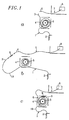
- the optical fiber 1 can be either a single sheathed fiber, a unitary ribbon formed of such associated fibers being arranged adjacent one on the other and embedded in an external sheath.
- a single fiber we will reason on a single fiber, the setting work of a ribbon leading to the same considerations.
- the terminal portion 3 of the fiber is coiled around a central nucleus 5 and emerges at the outside by one of the corners of the cassette.
- the end of this terminal portion 3 must in particular be connected to the homologous end 6 of a second fiber 7, to ensure a desired connection with a device any use, illustrated under reference 8.
- the diagram (c) in Figure 1 shows how the splice 9 and the extra length 10 must therefore be able to be accommodated at the inside of the cassette, the outer parts of the ends 3 and 6 of the two fibers 1 and 2 being reduced to the maximum.
- the splice can be mounted inside the cassette 4 in a fixed part thereof, or else be worn by the central core 5 of this same cassette, the structure and implementation constitute the elements essentials of the present invention.
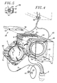
- Figures 2 and 3 illustrate on a larger scale the detail of the production of cassette 4 for the storage of the stripped terminal portion 3 of an optical fiber 1, in particular by prior removal of the outer sheath 11 which normally surrounds this fiber in the part current of it.
- the cassette 4 mainly consists of a housing 12, consisting of a flat bottom 13 and a peripheral edge 14 extending perpendicularly from this bottom.
- the housing 12 is made of a material suitable metal or plastic, light, easy to machine or mold and easy to handle. Also preferably, this case has a square profile with, in each of its four corners, passages, respectively 15 and 16, 17 and 18, two to two opposite according to each of diagonals of the housing, through which the fibers 1 and 7 and in particular their ends 3 and 6, can enter or exit as appropriate from the housing 19 delimited inside of this housing by the bottom 13 and the peripheral rim 14 of it.
- the bottom 13 of the housing 12 comprises a central counterbore 20, in which the core 5 of the cassette, this core consisting of a cylindrical element 21, engaging inside the counterbore by delimiting with the lateral edge thereof narrow clearance 22, at most equal to the half-diameter of the fiber 1 (or fiber 7), stripped, placed in the housing 19, which has a circular profile towards the element cylindrical 21 of core 5 and rectilinear zones 23 in each of the four sides of the peripheral edge 14.
- its peripheral edge 14 is made in such a way so that it has connecting portions 24, between the straight areas 23 and each of the passages 15 at 18 input or output fibers, which are suitably rounded to avoid the presence from any sharp angle likely to injure the bare end 3 or 6 of the corresponding fiber arranged inside the housing 19.
- the cylindrical element 21 of the core central 5 is mounted rotating inside the housing 12 of the cassette 4, for example being secured to the bottom flat 13 by means of a pivot 25 provided axially with a threaded part 26 cooperating with a blind bore 27, suitably tapped, provided in the center of element 21, the pivot 25 being stopped by a head 28 under the bottom 13, allowing the threaded part 26 to be screwed into this blind bore 27.
- the element 21 of the core 5 comprises a flat flange 29, extending parallel to this bottom and thus delimiting the housing 19 from above.
- This flange 29 has a circular outer edge 30 and delimits a narrow clearance 31 with a cover 32 secured from the peripheral edge 14 of the housing 12, the flange 29 and the cover 32 being arranged substantially in the same plane, the height of the element 21 being determined by construction to substantially match that of the edge 14.
- the clearance 31 is determined with a width sufficient to allow the fiber to penetrate into the cassette housing but nevertheless limited enough to prevent this fiber does not escape outside due to its elasticity clean, the fiber thus being trapped under the flange 29 and the cover 32.
- the cover 32 is produced in four distinct but identical elements, respectively 33, 34, 35 and 36, each of these elements having an edge 37 directed towards the nucleus having a curved profile of so as to follow that of the outer edge 30 of the flange 29, by delimiting with the latter the aforementioned game 31, which corresponds substantially to that of the fibers optics 1 or 7 leading to cassette 4, so the case facilitate their installation in the accommodation circular 19.
- the four elements 33 to 36 of the cover 32 are made using plates of a material relatively flexible plastic, preferably transparent, these elements being glued or otherwise fixed against the edge 24 of the box to the right of each of the zones straight lines 23 thereof, and extending from these to core 5.
- each element of cover has lugs 38, folded down towards inside the housing 19 to lock in position the splice, as illustrated in particular in Figure 3.
- the splice made can be directly carried by the core cylindrical 5 rotatably mounted in the housing 12, which has the advantage of being able to perform around this core several windings of the two ends of fibers joined by this splice, without limiting the dimension of the extra length, contrary to what can if necessary occur when the splice 9 is fixed on the housing in a fixed part thereof.
- Splices 99 can be housed in cavities appropriate of the rotating core (not shown to not not overload the drawing), but which can be formed each time by a simple recess of dimensions Suitable. These cavities can be distributed over the periphery of the nucleus, and in particular be one to one four.
- the 99 splices are placed in their cavities thanks to the flexibility of the flange 29 which can be slightly moved outward to allow the passage necessary before returning in place keeping each splice in its cavity.
- the equipment of the cassette 4 is completed, from one hand to using a fixing member 39 for each of the fibers to the right of its penetration into the housing 12, here for fiber 1 through input 16, for fiber 7 to across entrance 17, on the other hand by fitting out this case so as to allow it a presentation easy, from a storage device 40 of a plurality of such cassettes.
- the fixing member 39 is in particular arranged so to come fit into a reception accommodation suitable 41, here circular, provided by construction in the peripheral edge 14 of the housing at right of each of entry passages 15 to 18 or fiber exit.
- this fixing member 39 is simply constituted by two parallel washers 42 and 43, each comprising an internal recess 44, so as to allow, when these washers are applied one on the other and secured by screws 45 or the like, tighten the sheath 11 of the fiber in question between them, before the assembly is put in place in the reception housing 41 chosen.
- Each of the cassettes has in its four sides outside of the open notches 50 having preferably an omega outline, with a narrow part slightly flared 51, open to the outside and connecting inwards with a circular part 52.
- These rods each have a part 55 in the form of flat, so as to allow their passage in the narrow part 51 of the notches before, consecutively to a 90 ° rotation on itself when they are engaged in the circular part 52, these rods do not come to immobilize the cassettes.
- a cover 56 comprising returns vertical, respectively 57 and 58, which engage in the narrow parts 51 of the two notches 50 provided in the sides of the boxes opposite to that which cooperates with rods 53 and 54.
- a appropriate means of identification which may be appropriate consist of a brand, a colored marker, or more usually by a sign to distinguish them from to each other, avoiding the risk of errors when their manipulation.
- the mounting in rotation on itself of the core central 5 and the forecast of a counterbore 20 receiving the lower part of this core avoids all capstan and fiber blocking effect on the core between the entry and exit of this fiber in the cassette.
- the special constitution of the cover of the latter makes it easy to house the splice once it is done, avoiding leave the extra length outside the cassette previously used.
- cover 32 formed of its four flexible elements also allows, instead of pull the fiber as shown above, extract it to through clearance 31 which following the outline of the core circular, follows the shape of the fiber inside the cassette compartment.
- the assembly produced has a very small thickness, especially if the optical fiber contained in the cassette has no splices.
- the cassette housing is a slightly wider, the thickness thereof being therefore very slightly higher.
- the cassette according to the invention is simple to manufacture, easy to use, at a price of returns limited and allows rational storage of a high number of cassettes, without possibility of confusion between the various fibers leading to each of these cassettes individually.
- the successive cassettes in the support structure common can be distinguished by landmarks suitable (serial numbers, colors, special signs etc ...), allowing them to be easily extracted and then replace, once the intervention desired performed.
Landscapes
- Physics & Mathematics (AREA)
- General Physics & Mathematics (AREA)
- Optics & Photonics (AREA)
- Light Guides In General And Applications Therefor (AREA)
- Mechanical Coupling Of Light Guides (AREA)
Claims (17)
- Kassette für die Unterbringung und den Einzelschutz eines Endabschnitts einer optischen Einzelfaser (1) oder einer von einer Vereinigung solcher Fasern gebildeten Bandeinheit mit einem flachen Gehäuse (12) mit einem Boden (13), der an seinem Umfang mit einem Randanschlag (14) und mindestens einem Einlaß und mindestens einem Auslaß (15 bis 18) für den Endabschnitt der Faser oder des Bandes versehen ist, wobei das Innere des flachen Gehäuses in seiner Mitte einen zylindrischen Kern (5) enthält, der vom Boden des Gehäuses so vorspringt, daß er zwischen der Außenfläche des Kerns und dem Boden und dem Umfangs-Randanschlag des Gehäuses eine ringförmige Aufnahme (19) für die Unterbringung des Endabschnitts der Faser oder des Bandes begrenzt, wobei die Faser oder das Band dazu bestimmt sind, daß sie um den zylindrischen Kern mit einer genügenden Zahl von Windungen frei gewickelt werden, um außerhalb des Gehäuses eine gewünschte Überlänge (10) zu liefern, nachdem auf ihr Ende (3) außerhalb des Gehäuses ein Zug ausgeübt wurde, wobei diese Kassette dadurch gekennzeichnet ist, daß der zylindrische Kern (5) am Boden des Gehäuses um einen zum Boden senkrechten Mittelzapfen (25) drehbar montiert ist und der Boden (13) eine hohle Senkung (20) aufweist, in welche die Unterseite des drehbaren Kerns (5) mit einem begrenzten seitlichen Spiel (22) eindringt, das besonders kleiner als der halbe Durchmesser der Faser (1) ist, so daß beim Herausziehen der gewünschten Überlänge aus dem Gehäuse durch Ziehen das gemeinsame drehende Antreiben des Mittelkerns und der sich gegen diesen Kern festziehenden Windungen die Freisetzung einer gegebenen Zahl von Windungen auf dem Kern ermöglicht, wobei jede Blockierung der auf dem Mittelkern festgezogenen Windungen vermieden wird.
- Kassette nach Anspruch 1, dadurch gekennzeichnet, daß die Oberseite des drehbaren Kerns fest mit einem ebenen Flansch (29) verbunden ist, der parallel zum Boden (13) des Gehäuses verläuft und die ringförmige Aufnahme (19) zur Unterbringung der Faser (1) teilweise von oben abdeckt.
- Kassette nach Anspruch 2, dadurch gekennzeichnet, daß der Umfangs-Randanschlag (14) des Gehäuses (12) einen ebenen ringförmigen Deckel (32) aufweist, der zum Zapfen (25) des drehbaren Kerns (5) gerichtet ist, im wesentlichen in der Ebene des Flansches (29) verläuft und mit der Seite (30) des Flansches einen Zwischenraum (31) begrenzt, der für den Durchtritt der Faser (1) ausreicht.
- Kassette nach Anspruch 3, dadurch gekennzeichnet, daß das Gehäuse (12) einen quadratischen oder rechteckigen Querschnitt aufweist, der ringförmige Deckel (32) aus vier getrennten Elementen (33 bis 36) gebildet ist, wobei jedes dieser Elemente an einer der vier jeweiligen Seiten des Gehäuses angeordnet ist und jedes Element des Deckels mit einer nachgiebigen Zunge aus einem vorteilhafterweise transparenten Kunststoffmaterial ausgebildet ist, die einen kreisförmigen, zur Mitte des Gehäuses gerichteten Außenrand (37) aufweist, der sich im wesentlichen parallel zur Seite (30) des vom drehbaren Kern (5) getragenen Flansches (29) erstreckt.
- Kassette nach Anspruch 4, dadurch gekennzeichnet, daß der Umfangs-Randanschlag (14) des Gehäuses (12) in jeder seiner vier Ecken einen Eintrittsdurchlaß und/oder Austrittsdurchlaß (15 bis 18) der in diesem Gehäuse untergebrachten Faser (1) aufweist, wobei diese Durchlässe zwei und zwei gemäß den Diagonalen des Gehäuses angeordnet sind.
- Kassette nach Anspruch 5, dadurch gekennzeichnet, daß die Anschlußabschnitte (24) jedes Durchlasses zu der kreisförmigen Aufnahme (19) der Faser (1) im Inneren des Gehäuses (12) hin ein abgerundetes Profil aufweisen.
- Kassette nach einem der Ansprüche 4 bis 6, dadurch gekennzeichnet, daß das Gehäuse (12) außerhalb der ringförmigen Aufnahme (19) an seinen Seitenkanten nach außen offene Kerben (50) für die Befestigung oder Aufhängung des Gehäuses aufweist.
- Kassette nach Anspruch 7, dadurch gekennzeichnet, daß die Kerben (50) einen Omega-Umriß mit einem nach außen gerichteten engen Teil (51) aufweisen, an den sich nach innen ein im wesentlichen kreisförmiger Teil (52) anschließt.
- Kassette nach einem der Ansprüche 5 bis 8, dadurch gekennzeichnet, daß jeder Durchlaß in einer Ecke des Gehäuses (12) eine im wesentlichen kreisförmige in der Mitte gelegene Ausnehmung (41) für die Montage eines Elements zur Befestigung (39) des Außenmantels (11) der Faser (1) aufweist.
- Kassette nach Anspruch 9, dadurch gekennzeichnet, daß das Befestigungselement (39) aus zwei ebenen kreisförmigen Platten (42, 43) besteht, welche den Mantel (11) eben auf eben einspannen und durch Schrauben (44) oder dergleichen gegeneinander gehalten sind.
- Kassette nach einem der Ansprüche 4 bis 9, dadurch gekennzeichnet, daß zum Unterbringen einer Spleißung (9) oder einer Verbindungskopplung der optischen Faser (1) mit einer anderen Faser (7) die kreisförmige Aufnahme (19) im Inneren des Gehäuses (12) gegen die Innenseite des Umfangs-Randanschlags (14) desselben mindestens eine gerade längliche Zone (23) zum Anordnen diese Spleißung aufweist, die in das Gehäuse unter die das entsprechende Element des Deckels (32) bildende nachgiebige Zunge eingeführt wurde.
- Kassette nach Anspruch 11, dadurch gekennzeichnet, daß die Zunge des Deckels zum Inneren der kreisförmigen Aufnahme (19) vorspringende Finger (38) aufweist, um die Verbindungsspleißung (9) im Gehäuse (12) gegen den geraden Bereich (23) festzuhalten.
- Kassette nach einem der Ansprüche 4 bis 9, dadurch gekennzeichnet, daß der zylindrische Kern (5) an seinem Umfang in der Nähe der kreisförmigen Aufnahme (19) Verbindungsspleißungen (99) zwischen zwei Fasern trägt, deren Enden in das Innere des Gehäuses (12) eingreifen.
- Anordnung zur Unterbringung von optischen Fasern oder Bandeinheiten, die von einer Vereinigung solcher Fasern gebildet sind, mit einer Mehrzahl von Kassetten nach Anspruch 8, sowie mit einer Vorrichtung zur Lagerung oder Halterung dieser Kassetten, dadurch gekennzeichnet, daß sie mindestens eine Haltestange (53, 54) für diese Kassetten aufweist, welche homologe Kerben (50) ihrer jeweiligen Gehäuse (12) durchsetzt, um diese miteinander eben auf eben fest zu verbinden, ohne die Möglichkeit zu behindern, irgendeine der Kassetten um diese Tragstange zu schwenken.
- Anordnung nach Anspruch 14 in Abhängigkeit von Anspruch 8, dadurch gekennzeichnet, daß die Tragstange (53, 54) eine Abflachung (55) aufweist, welche es ermöglicht, die Kassetten bei einer Stellung der Stange im Inneren der mittleren Ausnehmung (52) der Omega-förmigen Kerben (50) zu blockieren oder den Austritt dieser Stange aus diesen Kerben in einer anderen, zur ersten senkrechten Stellung der Stange zu ermöglichen, in der die Abflachung in den von den Kerben nach außen gerichteten engen Teil (51) eingreift.
- Anordnung nach einem der Ansprüche 14 oder 15, dadurch gekennzeichnet, daß sie eine Vorrichtung zur. Verriegelung der Kassetten aufweist, die besonders aus einem Deckel (56) besteht, der auf der gegenüberliegenden Seite der Gehäuse (12) angeordnet ist, wobei dieser Deckel senkrechte Rücksprünge (57, 58) aufweist, welche in die engen Abschnitte von Kerben (50) eingreifen können, die auf dieser entgegengesetzten Seite vorgesehen sind.
- Anordnung nach einem der Ansprüche 14 bis 16, dadurch gekennzeichnet, daß jede Faser und/oder Kassette ein Mittel zur Markierung und Einzelidentifizierung aufweist.
Applications Claiming Priority (2)
| Application Number | Priority Date | Filing Date | Title |
|---|---|---|---|
| FR9413619 | 1994-11-14 | ||
| FR9413619A FR2726914B1 (fr) | 1994-11-14 | 1994-11-14 | Cassette pour le logement et la protection d'une fibre optique et dispositif pour le stockage d'une pluralite de telles cassettes |
Publications (2)
| Publication Number | Publication Date |
|---|---|
| EP0712018A1 EP0712018A1 (de) | 1996-05-15 |
| EP0712018B1 true EP0712018B1 (de) | 2002-08-14 |
Family
ID=9468778
Family Applications (1)
| Application Number | Title | Priority Date | Filing Date |
|---|---|---|---|
| EP95402473A Expired - Lifetime EP0712018B1 (de) | 1994-11-14 | 1995-11-06 | Kassette zur Unterbringung und zum Schutz einer optischen Faser und Anordnung zur Lagerung von optischen Fasern |
Country Status (3)
| Country | Link |
|---|---|
| EP (1) | EP0712018B1 (de) |
| DE (1) | DE69527762T2 (de) |
| FR (1) | FR2726914B1 (de) |
Families Citing this family (9)
| Publication number | Priority date | Publication date | Assignee | Title |
|---|---|---|---|---|
| FR2748576B1 (fr) * | 1996-05-09 | 1998-07-24 | Crespel Daniel | Dispositif pour lover des rubans ou des micro-gaines de fibres optiques, et leurs epissures ou coupleurs de raccordement |
| GB2368138A (en) * | 2000-10-17 | 2002-04-24 | Spirent Plc | Splice storage apparatus with peripheral store for optic fibre |
| CN101517446B (zh) * | 2006-09-13 | 2011-04-13 | 3M创新有限公司 | 带接头托盘的光纤线路管理系统 |
| DE102008010592A1 (de) * | 2008-02-22 | 2009-08-27 | Adc Gmbh | Glasfaser-Anschlussmodul |
| US8090234B2 (en) * | 2008-04-21 | 2012-01-03 | Adc Telecommunications, Inc. | Cable anchoring device |
| DE202009002488U1 (de) * | 2009-02-23 | 2009-04-30 | W-Hammer Gmbh | Lichtwellenleiter-Verteilerschrank |
| CN109323749B (zh) * | 2018-11-09 | 2022-03-08 | 威海北洋电气集团股份有限公司 | 光纤水听器阵列内的光纤收纳保护装置 |
| JP2022155788A (ja) * | 2021-03-31 | 2022-10-14 | コーニング リサーチ アンド ディヴェロップメント コーポレイション | 配線架 |
| CN114964339B (zh) * | 2022-06-17 | 2024-06-11 | 中国工程物理研究院激光聚变研究中心 | 一种光纤传感盒 |
Family Cites Families (6)
| Publication number | Priority date | Publication date | Assignee | Title |
|---|---|---|---|---|
| FR2567657B1 (fr) * | 1984-07-13 | 1986-11-21 | Capelle Bruno | Dispositif pour disposer des fibres optiques en boucles de lovage |
| FR2573544B1 (fr) * | 1984-11-20 | 1987-04-24 | Mars Actel | Support de raccordement de fibres optiques |
| US4666240A (en) * | 1985-02-01 | 1987-05-19 | Amp Incorporated | Splice organizer for optical cable splices |
| FR2600781B1 (fr) * | 1986-06-25 | 1991-05-03 | Constr Telephoniques | Support pour cassette de stockage de fibre optique |
| US4793682A (en) * | 1988-01-11 | 1988-12-27 | Gte Products Corporation | Fiber optic splice and fiber holder and housing therefor |
| US5263585A (en) * | 1992-05-07 | 1993-11-23 | Myriadlase, Inc. | Package for an elongated flexible fiber |
-
1994
- 1994-11-14 FR FR9413619A patent/FR2726914B1/fr not_active Expired - Fee Related
-
1995
- 1995-11-06 DE DE69527762T patent/DE69527762T2/de not_active Expired - Fee Related
- 1995-11-06 EP EP95402473A patent/EP0712018B1/de not_active Expired - Lifetime
Also Published As
| Publication number | Publication date |
|---|---|
| DE69527762D1 (de) | 2002-09-19 |
| FR2726914A1 (fr) | 1996-05-15 |
| EP0712018A1 (de) | 1996-05-15 |
| FR2726914B1 (fr) | 1997-01-24 |
| DE69527762T2 (de) | 2003-05-15 |
Similar Documents
| Publication | Publication Date | Title |
|---|---|---|
| EP0185923B1 (de) | Träger für optische Faserverbindungen | |
| EP0725468B1 (de) | Faseroptisches Verbindungsgehäuse | |
| EP2264502B1 (de) | Verbindungsverfahren von optischen Fasern | |
| EP0397587B1 (de) | Modul und Kabelverbindungsgehäuse mit optischen Fasern | |
| FR2748576A1 (fr) | Dispositif pour lover des rubans ou des micro-gaines de fibres optiques, et leurs epissures ou coupleurs de raccordement | |
| EP1224719A1 (de) | Führungsvorrichtung wenigstens eines langgestreckten biegsamen elements, wie kabel oder ähnliches, mit vorwiegend geschlossener kontur | |
| FR2848542A1 (fr) | Dispositif de conditionnement et de devidage de cable | |
| EP0253728A1 (de) | Aufnahmevorrichtung für optische Fasern | |
| EP0712018A1 (de) | Kassette zur Unterbringung und zum Schutz eine optischen Faser und Stapelvorrichtung für diese Kassetten | |
| FR2559916A1 (fr) | Methode utilisee dans le raccordement de fibres optiques pour constituer et stocker un troncon de fibre en reserve et dispositif s'y rapportant | |
| EP0855721B1 (de) | Faseroptisches Kabel | |
| EP0936486B1 (de) | Verbindungsdose für ein Kabel, insbesondere für ein faseroptisches Kabel | |
| EP0084984B1 (de) | Vorrichtung zur Herstellung einer Extremitätenebene optischer Fasern, die rund um eine axialsymmetrische Struktur verteilt sind | |
| FR2688897A1 (fr) | Prise optique. | |
| FR2814246A1 (fr) | Dispositif de rangement de surlongueurs de cables de fibres optiques | |
| EP0216683A1 (de) | Ein Magazin bildendes Werkzeug zum Anbringen irgend eines Artikels, insbesondere für Verkabelungskennzeichnungen | |
| EP2993151B1 (de) | Hochleistungs-trommel | |
| FR2745393A1 (fr) | Dispositif de support d'epissures, notamment pour fibres ou modules optiques | |
| EP0327451B1 (de) | Verteiler für Verkabelungszubehör, insbesondere für Endstücke | |
| EP0842445A1 (de) | Glasfaser verbindungskassette | |
| EP3163344B1 (de) | Mechanische schutzvorrichtung für optische fasern in einer kassette eines verteilerkastens für optische fasern | |
| FR2739460A1 (fr) | Bobine pour fibres optiques | |
| EP2439571A2 (de) | Glasfaserkabel-Anschlussgehäuse mit herausnehmbaren Kassetten zum Spleißen und zum Im-Schleier-Verlegen von Überlängen | |
| EP1012652B1 (de) | Verbindung für faseroptische kabel | |
| EP0891572B1 (de) | Kopplungsvorrichtung für wenigstens zwei mehrsträngige kabel |
Legal Events
| Date | Code | Title | Description |
|---|---|---|---|
| PUAI | Public reference made under article 153(3) epc to a published international application that has entered the european phase |
Free format text: ORIGINAL CODE: 0009012 |
|
| AK | Designated contracting states |
Kind code of ref document: A1 Designated state(s): DE FR |
|
| 17P | Request for examination filed |
Effective date: 19960917 |
|
| 17Q | First examination report despatched |
Effective date: 20010529 |
|
| RTI1 | Title (correction) |
Free format text: CASSETTE FOR THE HOUSING AND PROTECTION OF AN OPTICAL FIBRE AND INSTALLATION FOR THE STORAGE OF OPTICAL FIBRES |
|
| GRAG | Despatch of communication of intention to grant |
Free format text: ORIGINAL CODE: EPIDOS AGRA |
|
| GRAG | Despatch of communication of intention to grant |
Free format text: ORIGINAL CODE: EPIDOS AGRA |
|
| GRAH | Despatch of communication of intention to grant a patent |
Free format text: ORIGINAL CODE: EPIDOS IGRA |
|
| GRAH | Despatch of communication of intention to grant a patent |
Free format text: ORIGINAL CODE: EPIDOS IGRA |
|
| GRAA | (expected) grant |
Free format text: ORIGINAL CODE: 0009210 |
|
| AK | Designated contracting states |
Kind code of ref document: B1 Designated state(s): DE FR |
|
| REF | Corresponds to: |
Ref document number: 69527762 Country of ref document: DE Date of ref document: 20020919 |
|
| PLBE | No opposition filed within time limit |
Free format text: ORIGINAL CODE: 0009261 |
|
| STAA | Information on the status of an ep patent application or granted ep patent |
Free format text: STATUS: NO OPPOSITION FILED WITHIN TIME LIMIT |
|
| 26N | No opposition filed |
Effective date: 20030515 |
|
| PGFP | Annual fee paid to national office [announced via postgrant information from national office to epo] |
Ref country code: DE Payment date: 20081126 Year of fee payment: 14 |
|
| PGFP | Annual fee paid to national office [announced via postgrant information from national office to epo] |
Ref country code: FR Payment date: 20081126 Year of fee payment: 14 |
|
| REG | Reference to a national code |
Ref country code: FR Ref legal event code: ST Effective date: 20100730 |
|
| PG25 | Lapsed in a contracting state [announced via postgrant information from national office to epo] |
Ref country code: FR Free format text: LAPSE BECAUSE OF NON-PAYMENT OF DUE FEES Effective date: 20091130 |
|
| PG25 | Lapsed in a contracting state [announced via postgrant information from national office to epo] |
Ref country code: DE Free format text: LAPSE BECAUSE OF NON-PAYMENT OF DUE FEES Effective date: 20100601 |