EP0712095A2 - Verfahren und Vorrichtung zur Bilddatenkompression - Google Patents
Verfahren und Vorrichtung zur Bilddatenkompression Download PDFInfo
- Publication number
- EP0712095A2 EP0712095A2 EP95307694A EP95307694A EP0712095A2 EP 0712095 A2 EP0712095 A2 EP 0712095A2 EP 95307694 A EP95307694 A EP 95307694A EP 95307694 A EP95307694 A EP 95307694A EP 0712095 A2 EP0712095 A2 EP 0712095A2
- Authority
- EP
- European Patent Office
- Prior art keywords
- data
- memory
- image data
- format
- compression
- Prior art date
- Legal status (The legal status is an assumption and is not a legal conclusion. Google has not performed a legal analysis and makes no representation as to the accuracy of the status listed.)
- Granted
Links
Images


Classifications
-
- G—PHYSICS
- G06—COMPUTING OR CALCULATING; COUNTING
- G06T—IMAGE DATA PROCESSING OR GENERATION, IN GENERAL
- G06T9/00—Image coding
-
- G—PHYSICS
- G06—COMPUTING OR CALCULATING; COUNTING
- G06K—GRAPHICAL DATA READING; PRESENTATION OF DATA; RECORD CARRIERS; HANDLING RECORD CARRIERS
- G06K15/00—Arrangements for producing a permanent visual presentation of the output data, e.g. computer output printers
-
- G—PHYSICS
- G06—COMPUTING OR CALCULATING; COUNTING
- G06K—GRAPHICAL DATA READING; PRESENTATION OF DATA; RECORD CARRIERS; HANDLING RECORD CARRIERS
- G06K2215/00—Arrangements for producing a permanent visual presentation of the output data
- G06K2215/0002—Handling the output data
- G06K2215/0005—Accepting output data; Preparing data for the controlling system
- G06K2215/0014—Transforming the printer input data into internal codes
Definitions
- the present invention generally relates to an apparatus and method for storing image data into a memory and particularly relates to a technique for compressing image data or changing the data format thereof to thereby make it possible to store the image data into a memory having an insufficient capacity.
- An image forming apparatus such as a display driver, a printer, etc., is generally designed so that, in an image forming process, all image data received from a host apparatus are once stored in the form of intermediate codes on a memory and successively read out and converted into real images to be displayed or printed out through a print engine.
- a specific example of conventional image processing systems comprises a host apparatus 1, an image forming apparatus 2, and an image display output apparatus 3.
- the host apparatus 1 is constituted by a personal computer
- the image forming apparatus 2 is constituted by a circuit for controlling the inside of a printer or by a circuit for outputting a signal to a display
- the image display output apparatus 3 is constituted by a print engine of the printer or by the display.
- the image forming apparatus 2 includes a data receiving portion 4, memories 5 and 6, an image processing portion 7, a memory management portion 8, an image display portion 9, and a display buffer 10.
- the data receiving portion 4 receives data from the host apparatus 1 and temporarily stores the received data into the memory 5 as a system heap.
- the image processing portion 7 reads the received data from the memory 5 and analyzes the data to generate image data in the form of intermediate codes.
- the memory management portion 8 which serves to secure/release the memory 6 as an application heap, searches the memory 6 for a free memory area of a size requested by the image processing portion 7 and stores the intermediate code form image data from the image processing portion 7 into the free memory area. If there is no free memory area which can be secured, then the memory management portion 8 immediately outputs memory error to the image processing portion 7.
- the image display portion 9 successively reads the intermediate code form image data from the memory 6, converts the data into complete bit map form real image data and develops the real image on the display buffer 10. This real image is read from the display buffer 10 into the image display output apparatus 3 and displayed or printed out.
- the memory management portion 8 returns memory error to the image processing portion 7 immediately when the memory management portion 8 cannot find any free memory area for storing image data from the memory 6, memory-over error is apt to arise when particularly large image data is processed and, furthermore, the image processing portion 7 must perform complex processing for failure in securing the free memory area.
- the image display portion 9 must perform a process of converting the complex intermediate codes stored in the memory 6 into a real image and a process of developing the real image on the display buffer 10, there arises a problem in that image formation is apt to end in failure when the image forming process becomes too late for the increase in quantity of intermediate codes or the complication of the image forming process caused by the intermediate codes.
- the original image data of high resolution is to be converted into image data of low resolution
- the original image data can be converted only into image data of low resolution of a specific level which is set in advance in accordance with the specifications of the print engine or mechanism controller.
- the original image data of 600dpi ⁇ 600dpi can converted only into image data of 300dpi ⁇ 300dpi.
- the image data of 300dpi ⁇ 300dpi is 1/4 as small in the number of pixels as the original image data
- the small size image 1/4 as small in area as the original image is outputted if the image data of 300dpi ⁇ 300dpi is directly displayed or printed out. Therefore, to output the same size image as the original image, it is necessary to employ a method of doubling laser beam size or dot size of the printer, a method of doubling the number of scanning lines in the display unit, or the like. Therefore, the configuration of the printer engine or engine controller must be complicated to make such operation possible. That is, hardware and software structure adapted to single resolution cannot be used.
- An object of the present invention is to reduce the size of a necessary memory area as greatly as possible when image data are stored in a memory.
- Another object of the present invention is to secure a free memory area for storing new image data into a memory area already fully filled with image data to thereby prevent memory-over error from appearing frequently.
- a further object of the present invention is to suppress the processing for converting intermediate codes into a real image so that the processing is effected not excessively to thereby prevent error from occurring in the image forming processing when image data is to be stored in a memory in the form of intermediate codes as a general rule.
- a further object of the present invention is to make a user surely recognize shortage of a memory to which image data is to be stored to thereby help the user to properly extend the memory.
- a further object of the present invention is to adjust compressibility substantially nearly stagelessly while suppressing lowering of picture quality in the case of shortage of memory for storing image data to thereby make it possible to compress the image data with necessary and sufficient compressibility to eliminate shortage of memory.
- a further object of the present invention is to perform a process of restoring the original image from compressed image data and displaying or printing out the original image by using only hardware and software structure adapted to single resolution.
- At least a part of image data is compressed and the compressed image data is stored into a memory in the case where there is the possibility of shortage of the free area of the memory when the image data is to be stored into the memory.
- a value concerning the processing quantity of the compression is counted. When the thus counted value exceeds a predetermined threshold, the user is informed.
- the value concerning the processing quantity of the compression there can be employed, for example, the quantity of data compressed before all image data are stored into the memory, the time elapsed from the start of the compression of the image data before all image data are stored into the memory, or the like.
- elimination of shortage of memory is attained by compressing data already stored in the memory or new data to be stored into the memory when there arises a risk of shortage of memory in the case where image data are to be stored into the memory.
- the processing quantity of the compression executed becomes very large, the user is informed.
- the user can know shortage of memory, so that a measure to extend the memory, or the like, can be taken easily.
- a first data format such as, for example, intermediate code into a memory
- a second data format such as, for example, bit map data or not. If the judgment result is affirmative, each element of the image data is stored, not in the first data format but in the second data format, into the memory.
- image data are stored, for example, in the form of intermediate codes, into the memory and then the intermediate codes are converted into bit map data to be displayed or printed out
- image data are stored, not in the form of intermediate codes but in the form of bit map data, into the memory when the data size of the intermediate codes is larger than the data size of the bit map data. Accordingly, because image data are stored into the memory in the form of a smaller data size selected from the data size of intermediate codes and the data size of bit map data, wasteful consumption of memory can be saved so that, as a result, memory error hardly arises.
- the free memory area is increased by erasion or compression of data in the memory so that the free memory area of a sufficient capacity is secured easily and, as a result, memory error hardly occurs.
- band data in the form of intermediate code is retrieved and compressed.
- image data are stored, in a first data format such as, for example, intermediate codes, into a memory so that the image data of the first data format are read from the memory and converted into a second data format such as, for example, bit map data to be outputted.
- a judgment is made upon each element of image data to be stored into the memory as to whether a value concerning the processing quantity of conversion from the first data format to the second data format exceeds a predetermined threshold or not. When the judgment result is affirmative, each element is stored, not in the first data format but in the second data format, into the memory.
- the value concerning the processing quantity of conversion of the data format there can be employed, for example, the drawing area of each element designated by the intermediate code of each element.
- the quantity of work for conversion from the intermediate codes to the bit map data at the stage of displaying or printing-out decreases so that error caused by the lag of this work can be reduced.
- securing a free area of a sufficient capacity is attained by compression of image data when there is the possibility of shortage of the free area of the memory for storing the image data.
- one data format is selected from a plurality of data formats different in expected compressibility so that the original data format of the image data is converted into the selected data format.
- the thus converted image data is compressed again, so that securing a free area of a larger capacity than the previous capacity is attained.
- the data format conversion and the data compression are repeated until the free area of a sufficient capacity can be secured. In the repetition, the conversion of data format is performed stageously so that expected compressibility is increased by one rank compared with the previous expected compressibility.
- the plurality of data formats there can be employed various kinds of bit map data different in spatial frequency, for example, in one or both of longitudinal and transverse directions with respect to a two-valued image such as a character, a line drawing, or the like. Further, with a multi-gradation image such as a photograph, there can be employed, for example, various kinds of bit map data different in the number of expressible gradations. Further, it is preferable that the plurality of data formats are within a range where distinction on real image among the various data formats substantially cannot be recognized by naked eyes. Further, it is preferable that the various data formats are equal to each other in formal resolution.
- the original image data is, first, converted into data of a compressible format and the data of the compressible format is compressed. If there is shortage of memory still as a result, the data is converted into other data of another data format capable of obtaining higher compressibility and the other data is compressed. If shortage of memory cannot be eliminated still, conversion into another data format to obtain further higher compressibility is made and the data is compressed. Such a series of operations can be repeated.
- stageous adjustment of compressibility in which the original image is converted at first, into a data format to obtain the lowest compressibility so that the data is compressed, and in which the original image is then gradually converted into a data format to obtain higher compressibility so that the data is compressed.
- the free memory area of a sufficient capacity is secured at a certain stage, success of compression is judged at the stage so that compression with higher compressibility than necessary is prevented. Accordingly, lowering of picture quality caused by data conversion can be suppressed to minimum requirement.
- an apparatus for storing image data in a memory comprising: means for determining that a shortage of memory is likely to occur; and memory releasing means comprising compression means for compressing at least a part of image data which is stored, or is to be stored, in the memory, and/or erasion means for erasing any erasable data stored in the memory.
- the present invention further provides a method of storing image data into a memory, as executed by the aforementioned apparatus.
- the apparatus and method of the present invention are adapted preferably to an image forming apparatus such as a printer or a display, it is not limited thereto and can be applied to various fields in which image processing must be performed under a memory having a limited size.
- Fig. 2 is a diagram for explaining the outline of a system in which processing is performed after one page is partitioned into bands, in an embodiment of a print information processing apparatus according to the present invention.
- One-page's printing paper 11 is divided into N virtual bands 12 so that these virtual bands 12 are successively processed by using a plurality of physical bands 13 on an RAM.
- the number of physical bands is made 3, judging from the optimality of processing efficiency. The reason is that three physical bands are optimal for performing virtual band processing efficiently without waiting time and for avoiding redundant memory consumption.
- Fig. 3 shows a map for use of the RAM in this embodiment.
- An area for the physical bands 13 is provided so as to be separated from an area for work memory 22.
- a reception buffer 23 for receiving print information from a host computer is secured as another area on the RAM.
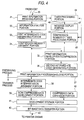
- Fig. 4 shows the functional configuration of this embodiment. A flow of processing of print information 30 in a certain virtual band as a subject to be processed will be described with reference to this drawing.
- the virtual band contains character data such as "ABC”, etc., graphic data expressed in a bit image, and graphic data expressed in vector.
- print information 30 delivered from the host through a communication line contains a value of ASCII code "41", an output position, a size, etc.
- print information 30 contains bit composition information, output position, size, etc.
- graphic data expressed in vector such print information 30 contains numerical formulae, drawing position, size, etc. Therefore, these parts of print information 30 are received by the reception buffer 23 constituting a print information receiving portion 31 and stored in the reception buffer 23.
- the intermediate codes are index data in which information such as the kind of the print information 30, the storage position of data necessary for drawing, the position of drawing in page, etc., is held in a predetermined format defined by the kind thereof.
- Fig. 5 shows various intermediate code formats. Although intermediate code formats are classified into five or more kinds by the form of development, only three kinds of intermediate code formats are shown here as typical examples.
- Any intermediate code has a code name (CN) 51, in its first place, indicating the kind of information.
- the code name 51 contains information concerning the source type for discriminating the type of the source data among a 16-bit word type, an 8-bit byte type and a mixture type, and information concerning development type as shown in the drawing.
- a standard type shown in Fig. 5(A) at least has a source pointer (SP) 52 indicating a source storage position, and an object pointer (OP) 53 indicating a destination position, and further has information of an object width (OW) 54 and an object height (OH) 55 when scale-up/down is applied to the source data.
- SP source pointer
- OP object pointer
- One intermediate code has about 60 bytes.
- a straight line type shown in Fig. 5(B) shows an intermediate code applied to graphic data expressed in vector.
- the intermediate code has no source pointer 52 because source information is certain to be linear. All the vector graphic data are expressed by straight lines in the raster direction, so that an intermediate code corresponding to each straight line is generated.
- a compressed type shown in Fig. 5(C) shows an intermediate code generated to manage one virtual band when the virtual band is developed into a bit image and compressed.
- the intermediate code contains SP 52 indicating the storage position of the compressed bit image, OP 53 indicating the destination position, and OW 54 indicating a gap for a continuous data group expanded.
- a judgment is first made as to which band of the N virtual bands contains information to be processed, so that an intermediate code of a predetermined format is generated in the thus located virtual band and stored in a print information processing/holding portion 37.
- the print information processing/holding portion 37 is specifically realized by an RAM and it is a portion of the work memory 22 in Fig. 3.
- the following three conditions are checked by a compression necessity judgment portion 34 at any time. At a point of time when any one of the conditions is satisfied, the situation of processing is made to branch to a print information development/compression portion 35 on the basis of a decision that data subjected to processing needs to be compressed.
- an intermediate code for managing the compressed bit image data is generated by a second intermediate code generating portion 36.
- This intermediate code is of a compressed type shown in Fig. 5(C), so that only one intermediate code is generated in order to manage this virtual band.
- the print information 30 delivered through the communication line by the processing up to now is processed on the RAM of the print information processing/holding portion 37, and necessary data are converted into intermediate codes or compressed bit images and stored.
- a preserving process is completed.
- the preservation of all intermediate codes in one page and of compressed bit images corresponding to necessity is completed.
- the bit images are transferred to the printer engine by a process which will be described later. While the bit images are transferred, the preserving process for the next page is carried out by using a free area of the RAM.
- the preserving process for the secondary next page is further carried out. In this manner, rotation is made efficiently.
- the compression number-of-times processing portion 45 counts the number of times by which the print information development/compression portion 35 carries out a process of developing intermediate code or print information to bit images and compressing the bit images, for each page in the preserving process thereof (that is, the number of times is the number of character/graphic data, or the like converted into compressed bit images and hereinafter referred to as "compression number-of-times").
- the compression number-of-times processing portion 45 outputs a count-up signal 48 to a message display portion 47.
- the count-up signal 47 When the count-up signal 47 is outputted from the compression number-of-times processing portion 45, this means the fact that a very long time is required for the preserving process because the number of times of compression per page is very large.
- One main cause of such very long processing time is that the band buffer 13 or work area 22 of a sufficient capacity which is required to convert all data of one page into intermediate codes and to hold the all data cannot be secured because of the small capacity of the RAM. To eliminate this main cause, it may extend the RAM.
- the message display portion 47 displays a predetermined message on a liquid crystal display of the printer, a display of the host computer, or the like. This message serves to tell the user that the RAM is preferably required to be extended in order to provide a comfortable printing environment. For example, the message is as follows: "This printing will take a very long time. Extension of RAM is required for shortening the time.”
- This message display is made at a time suitable for calling the user's attention and continued for a suitable period.
- this message is displayed only for a predetermined period when the count-up signal 47 is outputted, a method in which this message is continuously or intermittently displayed in a period of from a point of time when the count-up signal 47 is once outputted to a point of time when the preservation or printing of the page is completed, a method in which this message is continuously or intermittently displayed up to the completion of printing of the whole document, or the like.
- a timer processing portion 44 as represented by the broken line in Fig. 4 may be provided instead of or in addition to the aforementioned compression number-of-times processing portion 45.
- This timer processing portion 44 starts time counting concerning each page at a point of time when print information 30 in each page enters the print information receiving portion 31, and this timer processing portion 44 continues the time counting concerning each page until the preserving process for each page is completed. If the time count value reaches a predetermined threshold when the time counting is continued, a time-up signal 46 is outputted to the message display portion 47. Upon reception of this time-up signal 46, the message display portion 47 displays the aforementioned message by the aforementioned suitable method in the same manner as in the case of reception of the count-up signal 47.
- An intermediate code interpretation judgment portion 38 reads the intermediate code name 51 and interprets first whether the data is compressed data or not. When the data is not compressed data, the data goes to a non-compressed data development portion 39. When the data is compressed data, the data goes to a compressed data expansion portion 40.
- the non-compressed data development portion 39 develops a certain source data into a bit image on the basis of intermediate code management information contained in the virtual band to be processed, and writes the bit image in a development storage portion 41, specifically, writes the bit image in a designated position of a predetermined physical band 13 on the RAM.
- the thus generated bit image of the virtual band has one-to-one correspondence with respect to the resolution of the printer engine which is used when the bit image is outputted. At this time, distinction among character data, vector graphic data and bit image graphic data is eliminated.
- the compressed data expansion portion 40 expands the compressed bit image preserved on the RAM of the print information processing/holding portion 37 by a predetermined expansion method and writes the expanded bit image in the physical band 13 of the development storage portion 41 on the basis of intermediate code management information contained in the virtual band to be processed.
- the thus generated bit image of the virtual band also has one-to-one correspondence with respect to the resolution of the printer engine which is used when the bit image is outputted.
- Fig. 6 is a flow chart of the preserving process showing a flow of preservation of one-page's print information 30 into the work memory 22 in this embodiment.
- bit images for the virtual band are collected, the bit images are compressed and preserved in the work memory 22 (S68). In this occasion, the number of times of compression is increased by one whenever one character, graphics, or the like, is compressed (S69). The number of times of compression at this time is counted up.
- print information 30 for the next virtual band is received from the receiving buffer 23 on the RAM again.
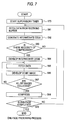
- Figs. 7 and 8 show a flow of the one-page preserving process in the structure in which a judgment is made by the timer processing portion 44 as to whether the message display is to be made or not.
- a supervisory timer is started at a point of time when the input of one-page's print information from the host is started (S73). Then, the same preserving process as described above in the case of Fig. 6 is started, so that the supervisory timer operates until the one-page preserving process is completed.
- the supervisory timer generates an interruption signal periodically so that the timer process shown in Fig. 8 is carried out on the basis of this interruption. In the timer process, the timer count value is increased (S81), so that when the count value reaches a predetermined threshold (S82), the aforementioned message is displayed (S83).
- the number of times of compression or the processing time is monitored to thereby judge whether the capacity of the RAM is sufficient or not, so that when the capacity of the RAM is insufficient, the message is outputted to give the user a proposal for extension of the RAM.
- the user can determine freely whether this proposal is neglected or not. If this message is displayed frequently, this means the fact that the capacity of the RAM is insufficient for the general use condition of the user. Accordingly, by extending the RAM according to the proposal, the opportunity of compressing bit images is reduced so that the printing process can be completed in a shorter time than the conventional case. Accordingly, it is easy for the user to adjust the memory capacity of the printer so as to be suitable for the use condition of the user.
- Fig. 9 shows the overall configuration of the second embodiment of the present invention.
- this system comprises a host apparatus 110, an image forming apparatus 120, and an image display output apparatus 140.
- the host apparatus 110 is, for example, a personal computer
- the image forming apparatus 120 is a control circuit in the inside of a printer or a circuit for outputting a signal to a display
- the image display output apparatus 140 is a print engine of a printer or a display.
- the image forming apparatus 120 includes a data receiving portion 130, a command analysis portion 131, an image forming portion 132, a memory management portion 133, an image display portion 134, a memory 170 as a system heap, a memory 171 as an application heap, and a display buffer 172.
- the image forming portion 132 has a size limit judgment portion 150, an area limit judgment portion 151, and a real image generating portion 152.
- the memory management portion 133 has a synchronization releasing portion 160, a memory compression portion 161, and a data conversion portion 163.
- the data receiving portion 130 receives data from the host apparatus 110 and stores the data in a receiving buffer provided in the memory 171.
- the command analysis portion 131 reads the data stored in the receiving buffer, analyzes the data and feeds a corresponding drawing request to the image forming portion 132.
- the drawing request is constituted by a series of function calls for calling various drawing functions possessed by the image forming portion 132.
- the image forming portion 132 divides one page as a subject of processing into a plurality of bands and converts the drawing request from the command analysis portion 131 into an intermediate code for each band.
- the intermediate code is checked by the size limit judgment portion 150 and the area limit judgment portion 151 before the intermediate code is registered into the memory 171 through the memory management portion 133.
- the size limit judgment portion 150 judges whether the data size of the intermediate code in each band exceeds the data size of a real image or not. The judgment is made by comparing the data size of the intermediate code with a threshold which is set in advance.
- a threshold there is used, for example, a value obtained by multiplying by a predetermined coefficient a value obtained by dividing the maximum block size of the page as a subject of processing by the number of bands.
- the area limit judgment portion 151 judges whether there is the possibility that image formation results in failure (overrun error) because the conversion (drawing process) of the intermediate code into the real image by an image display portion 134 which will be described later is too late for the image forming operation of the image display output apparatus 140. This judgment is made by comparing the drawing area designated by the intermediate code with a limit area which is calculated in advance as an area in which image formation does not result in failure.
- the limit area means an area in which drawing with respect to a certain band can be made in a predetermined time.
- this area is a drawing area in which all procedures of logic operation, shift process, mask process and scale-up process, etc., for example, as obtained from an evaluation function which is obtained correspondingly to each intermediate code, can be executed in a drawing time allowed for the development of one band.
- the intermediate code is directly registered into the memory 171 by the memory management portion 133.
- the intermediate code is delivered to the real image generating portion 152.
- the real image generating portion 152 converts the intermediate code into a complete bit map format real image data (hereinafter this conversion is referred to as "beforehand development")
- the beforehand developed real image data is registered into the memory 171 by the memory management portion 133.
- the memory management portion 133 registers the intermediate code generated by the image forming portion 132 or the beforehand developed real image data in the memory 171. For this registration, the memory management portion 133 tries to search the memory 171 for a free memory area of a capacity required for the registration and to secure the free memory area. If the free memory area can be secured successfully, the registration is made normally. If the free memory area of a sufficient capacity cannot be secured, however, the synchronization releasing portion 160 in the memory management portion 133 is called out.
- the synchronization releasing portion 160 which is started when the free memory area cannot be secured, checks whether any data waiting for display on the image display output apparatus 140 exists in the memory 171 or not. If the result of checking makes a decision that there is any data, the data is released (erased from the memory 171) as displayed data to thereby increase the free memory area of the memory 171 at a point of time when the display on the image display output apparatus 140 is completed. On the contrary, when the result of checking makes a decision that there is no data waiting for display or when the free memory area of a sufficient capacity cannot be secured even though the displayed data is released, the memory compression portion 161 is called out next.
- the memory compression portion 161 converts the intermediate codes into real image data and then the real image data is compressed to thereby increase the free memory area of the memory 171.
- the memory compression portion 161 calls out the data conversion portion 162 which will be described later, and delivers the real image data to the data conversion portion 162 to thereby make the data conversion portion 162 convert the real image data into data of a compressible format and then try to compress the data of the compressible format.
- the data conversion by the data conversion portion 162 is designed so as to be performed by a plurality of times while a plurality of conversion methods are used selectively. That is, conversion methods can be selected stageously so that compressibility is apt to be increased gradually whenever number of times increases.
- the memory compression portion 161 first selects an initial stage data conversion method and tries to compress the data converted by the method. If as a result, the free memory area of the memory 171 can be secured, the memory compression portion 161 judges the success of compression and makes the compressing process completed. If as a result, the free memory area cannot be secured yet, the memory compression portion 161 selects the next stage conversion method higher in compressibility and tries to compress the data converted by the method. The operation of checking whether the free memory area can be secured or not, is repeated until the free memory area of a sufficient capacity can be secured.
- the memory compression portion 161 outputs to the command analysis portion 131 error indicating the fact that the free memory area cannot be secured.
- the memory compression portion 161 expands the compressed real image data in the memory 171 to the original intermediate code when the compressed real image data is displayed or printed or when the free memory area is increased so that there is no necessity of storing the real image data in the compressed form.
- the data conversion portion 162 converts the real image data in the memory 171 into data of a compressible format when the data conversion portion 162 is requested by the memory compression portion 161. Conversion methods having a plurality of stages are prepared for the data conversion portion 162 so that compressibility is apt to be increased gradually. A conversion method designated by the memory compression portion 161 is selected therefrom.
- data of a compressible format means data of a format which has a repetition pattern appearing more frequently than the original data.
- conversion methods having a plurality of stages in which compressibility is apt to be increased gradually means conversion methods having a plurality of stages in which the frequency of appearance of a repetition pattern increases gradually.
- the following three conversion methods are taken with respect to a two-valued image such as a line drawing or a text.
- the size of the image that is, the longitudinal and transverse numbers of pixels, that is, formal resolution
- the spatial frequency that is, the substantial resolution
- the size of the image after conversion that is, the formal resolution thereof is also 600dpi ⁇ 600dpi whereas the changing step of the dot pattern in the image, that is, the substantial resolution of the image after conversion is two-dot unit (equivalent to 300dpi) though that of the original image is one-dot unit.
- a conversion method having a plurality of stages with respect to a half-tone image such as a photograph there is, for example, a method in which a plurality of half-tone dot patterns (see Figs. 15 and 16) different in gradation are prepared in advance so that the original image data is converted into image data expressed in a half-tone dot pattern with designated gradation by stegeously and selectively using the plurality of half-tone dot patterns. This method will be described later in detail.
- the data conversion portion 162 converts the original real image data into data of a compressible format in the aforementioned manner, the data of a compressible format is fed to the memory compression portion 161 and compressed as described above.
- the image display portion 134 band-by-band reads image data from the memory 171 and develops the image data into the form of real image data on the display buffer 172. If in this occasion, the image data are registered in the form of intermediate codes into the memory 171, the intermediate codes are read and converted into real image data and then the real image data are developed on the display buffer 172. If the image data are contrariwise registered in the form of real image data into the memory 171, the real image data are read and directly developed on the display buffer 172. If the image data are in the form of compressed data, the compressed data are expanded into real image data and developed on the display buffer 172. The real image data thus developed on the display buffer 172 are fed to an image display output apparatus 140 and displayed or printed out.
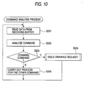
- Fig. 10 shows a flow chart of a command analysis process in the command analysis portion 131.
- step S201 data are read first from the receiving buffer in the memory 170 (step S201) and each command delivered from the host apparatus 110 is analyzed (step S202). If the command is recognized to be a drawing command as a result of the analysis (step S203), a corresponding drawing request is issued to the image forming portion 132 (step S204). If the command is contrariwise recognized to be other than the drawing command as a result of the analysis in the step S202, a process corresponding to the command other than the drawing command is carried out (step S205).
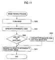
- Fig. 11 shows a flow chart of an image forming process in the image forming portion 132.
- An intermediate code is generated on the basis of the result thereof (step S207).
- step S208 a judgment is made as to whether the data size of this intermediate code exceeds the data size of the real image data or not. If the result is negative, a limit area in which over-run error is avoided is calculated with respect to the intermediate code and then a judgment is further made as to whether the drawing area designated by the intermediate code exceeds the calculated limit area or not (step S208). As a result, if the data size of the intermediate code exceeds the data size of the real image or if the drawing area of the intermediate code exceeds the limit area, the intermediate code is converted into real image data (step S209) and the memory management portion 33 is requested to register the real image data into the memory 171 (step S210).
- the memory management portion 133 is requested to register the intermediate code generated in the step S207 into the memory 171 directly (step S210).
- Fig. 12 shows a flow chart of a memory securing process in the memory management portion 133.
- a block having a free area corresponding to the data size of the intermediate code or real image data to be registered is first retrieved from the memory 171 (step S310). If, as a result of the retrieval, a free area is found (step S311), a pointer of the free area is returned to the command analysis portion 131 to thereby make this routine terminated with success of memory securing (step S312).
- step S316 If a decision that there is no display image is made in the step S313, on the contrary, a memory compression request is issued to the memory compression portion 161 (step S316). If, as a result, memory compression is made with success, a retrial is made to secure a free area because there is a possibility that a free area is generated in the memory 171 (step S310). If memory compression is failed on the contrary, memory error is outputted to the command analysis portion 131.
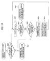
- Fig. 13 shows a flow chart of a memory compression process in the memory compression portion 161.
- a judgment is made as to whether there is any compressible data that is, data converted from the intermediate code format into the real image in order to perform beforehand development on the memory 171) in the memory 171 or not (step S420). If, as a result of the judgment, a decision is made that there is any compressible data, the real image data (that is, original image data) is compressed (step S421). Then, a judgment is made as to whether the data compression of the step S421 resulted in success or not (that is, whether the free memory area could be secured or not) (step S422). If a decision is made that the data compression was succeeded, the command analysis portion 131 is informed that the data compression resulted in success (step S423).
- compressible data that is, data converted from the intermediate code format into the real image in order to perform beforehand development on the memory 171 or not
- step S422 If a decision is contrariwise made in the step S422 that compression resulted in failure (that is, the free memory area could not be secured), the original real image data is converted into data of a more compressible format and then the process for compression is restarted.
- the data conversion portion 162 is called out and a judgment is made as to whether a data conversion method for conversion into a more compressible format can be designated or not (step S426). That is, because various kinds of methods for multistageous conversion are prepared as described above, a judgment is made as to whether among those various methods there is any method of a stage which has been not tried yet. Of course, the result of the judgment is YES at first. Therefore, a conversion method of an initial stage is first designated for the data conversion portion 162 (step S425) and the data conversion portion 162 is requested to convert the original image data by the conversion method (step S426).
- step S421 the data converted by the data conversion portion 162 is received and compressed (step S421) and then a judgment is made as to whether this data compression resulted in success or not (step S422).
- step S423 the command analysis portion 131 is informed that the compression resulted in success.
- step S424 again in order to perform compression after data conversion into data of a more compressible format.
- step S424 a judgment is made as to whether there is any data conversion method of the next stage or not. If there is any conversion method of the next stage, a request is made to convert the data by using the method, the thus converted data is tried to be compressed, and then a judgment is made as to whether the compression resulted in success or not (steps S425, S426, S421 and S422).
- step S424 In the case where compression contrariwise still resulted in failure though compression was made after conversion by the data conversion method of the last stage, a decision is made in step S424 that it is impossible to designate any more conversion method, and then the command analysis portion 131 is informed that the compression resulted in failure (step S427). Similarly to this, also in the case where there is no compressible data in step S420, the command analysis portion 131 is informed that the compression resulted in failure (step S427).
- Fig. 14 shows a flow chart of a data conversion process in the data conversion portion 162.
- the designation of the data conversion method is made by designating the number of gradations in the half-tone image.
- 5 gradations are designated at an initial stage and 17 gradations are designated at the next stage.
- step S502 data corresponding to the designated number of gradations are first extracted and expressed in gradations (step S502) successively in order (step S501) from the first byte of the original image data.
- Corresponding dot patterns are picked out from a half-tone table (in which dot patterns as shown in Figs. 15 and 16 which will be described later are stored) corresponding to the designated number of gradations, so that the original image data are replaced by the dot patterns (step S503). If a decision is made in the step S501 that the last byte of the original image data has been reached, the memory compression portion 161 is informed that the conversion of the original image data is completed (step S504).
- the aforementioned half-tone tables are tables showing the correspondence between the dot patterns of the original image data and the dot patterns 607 and 707 for 5 gradations and 17 gradations respectively shown in Figs. 15 and 16 which will be described later.
- the tables are programmed in advance.
- the original image data are replaced by the dot patterns 607 or 707 for 5 or 17 gradations in accordance with the correspondence in this table, by which the original image data can be converted into data of a compressible format with 5 or 17 gradations.
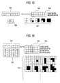
- Fig. 15 is an explanatory diagram of a conversion process in the case where 5 gradations are designated at the initial stage
- Fig. 16 is an explanatory diagram of a conversion process in the case where 17 gradations are designated at the second stage.
- Fig. 15 data of a compressible format with 5 gradations data of a format in which the density of one half-tone region is expressed in 5 gradations by using 5 kinds of dot patterns designated by the reference numeral 607 upon the assumption that a 4-pixel matrix of 2 ⁇ 2 pixels designated by the reference numeral 603 is defined to be one half-tone region.
- the data with 5 gradations are originally generated by applying a dither matrix as designated by the reference numeral 605 to the density value (0 to 4) of each half-tone region, this data conversion is designed as described above so that the data are generated by simple replacement with patterns in accordance with the half-tone table prepared in advance.
- 4 half-tone regions are formed by two bytes, that is, the first and second bytes as designated by the reference numeral 604, so that an upper half or a lower half of the 4 half-tone regions is assigned to one byte as designated by the reference numeral 601.
- a compressible data with 17 gradations data of a format in which the density of one half-tone region is expressed in 17 gradations by using dot patterns partly exemplified by the reference numeral 707 upon the assumption that a 16-pixel matrix of 4 ⁇ 4 pixels as designated by the reference numeral 703 is defined to be one half-tone region.
- the data with 17 gradations are originally generated by applying a dither matrix as designated by the reference numeral 705 to the density value (0 to 16) of each half-tone region, this data conversion is designed as described above so that the data are generated by simple replacement with patterns in accordance with the half-tone table prepared in advance.
- 2 half-tone regions are formed by four bytes, that is, from the first byte to the fourth byte, as designated by the reference numeral 704, so that a quarter portion of 2 half-tone regions is assigned to one byte as designated by the reference numeral 701.
- the variation of the dot pattern which can be taken by 4 pixels in the quarter portion of each half-tone region is as follows.
- dot patterns which appear in one byte are 81 kinds in 5-gradation data whereas such dot patterns are 43 kinds in 17-gradation data. That is, dot patterns which appear in the case of 17-gradation data are smaller in kind than dot patterns in the case of 5-gradation data.
- dot patterns decrease in kind the probability that patterns of adjacent bytes will coincide with each other increases, that is, the frequency of appearance of repetition patterns increases, so that compression is made easier. Accordingly, it can be said that 17-gradation data has a more compressible data format than the format of 5-gradation data.
- the data conversion portion 162 converts the original image data into data of a more compressible format stageously.
- the conversion method of the last stage is set to a limit in which distinction between the printed-out image and the original image is not recognized as remarkable distinction by human naked eyes.
- the original image data is stageously converted into image data of a more compressible format up to a limit in which distinction between the printed-out image and the original image cannot be recognized as remarkable distinction by human naked eyes, and then the compressible image data is compressed.
- data compression is made in necessary minimum requirement under substantially nearly stageless adjustment of compressibility without any remarkable lowering of picture quality, so that shortage of memory can be eliminated.
- a print engine or a mechanism controller adapted to single resolution can be used sufficiently.
- the conversion of the converted data is made by a method of performing compression while mainly paying attention to the repetition of one and the same pattern, there is little risk of erasing data necessary for restoring the original data from compressed data.
- the compression is substantially reversible compression. Accordingly, though lowering of picture quality caused by data conversion cannot but be allowed, a high-quality image can be restored so long as the lowering of picture quality caused by the data conversion is suppressed to a range in which there is substantially no problem.
Landscapes
- Engineering & Computer Science (AREA)
- Physics & Mathematics (AREA)
- General Physics & Mathematics (AREA)
- Theoretical Computer Science (AREA)
- General Engineering & Computer Science (AREA)
- Multimedia (AREA)
- Record Information Processing For Printing (AREA)
- Image Input (AREA)
- Image Processing (AREA)
- Storing Facsimile Image Data (AREA)
- Compression Of Band Width Or Redundancy In Fax (AREA)
Applications Claiming Priority (12)
| Application Number | Priority Date | Filing Date | Title |
|---|---|---|---|
| JP26506994 | 1994-10-28 | ||
| JP265069/94 | 1994-10-28 | ||
| JP26506994 | 1994-10-28 | ||
| JP325637/94 | 1994-12-27 | ||
| JP32563794 | 1994-12-27 | ||
| JP32563794 | 1994-12-27 | ||
| JP27175/95 | 1995-02-15 | ||
| JP2717595 | 1995-02-15 | ||
| JP2717595 | 1995-02-15 | ||
| JP226893/95 | 1995-09-04 | ||
| JP22689395 | 1995-09-04 | ||
| JP22689395A JP3582675B2 (ja) | 1994-10-28 | 1995-09-04 | 画像データをメモリに蓄積する装置及び方法 |
Publications (3)
| Publication Number | Publication Date |
|---|---|
| EP0712095A2 true EP0712095A2 (de) | 1996-05-15 |
| EP0712095A3 EP0712095A3 (de) | 1996-10-30 |
| EP0712095B1 EP0712095B1 (de) | 2005-03-09 |
Family
ID=27458638
Family Applications (1)
| Application Number | Title | Priority Date | Filing Date |
|---|---|---|---|
| EP95307694A Expired - Lifetime EP0712095B1 (de) | 1994-10-28 | 1995-10-27 | Verfahren und Vorrichtung zur Bilddatenkompression |
Country Status (4)
| Country | Link |
|---|---|
| US (1) | US5852710A (de) |
| EP (1) | EP0712095B1 (de) |
| JP (1) | JP3582675B2 (de) |
| DE (1) | DE69534054T2 (de) |
Cited By (2)
| Publication number | Priority date | Publication date | Assignee | Title |
|---|---|---|---|---|
| EP0817111A3 (de) * | 1996-07-05 | 2002-10-09 | Canon Kabushiki Kaisha | Bilderzeugungsverfahren und -vorrichtung |
| CN117008571A (zh) * | 2023-07-14 | 2023-11-07 | 重庆青山工业有限责任公司 | 一种nvm数据故障诊断及处理的控制方法 |
Families Citing this family (16)
| Publication number | Priority date | Publication date | Assignee | Title |
|---|---|---|---|---|
| WO1997033219A1 (en) * | 1996-03-04 | 1997-09-12 | Copyer Co., Ltd. | Image processor |
| US6538764B2 (en) * | 1996-04-12 | 2003-03-25 | Canon Kabushiki Kaisha | Printing apparatus, information processing apparatus, data processing method for use in such an apparatus, and storage medium storing computer-readable program |
| JP3580982B2 (ja) * | 1997-04-30 | 2004-10-27 | パイオニア株式会社 | 情報記録方法及び装置 |
| US6112208A (en) * | 1997-08-25 | 2000-08-29 | Fujitsu Limited | Data compressing method and apparatus to generate bit maps in accordance with extracted data symbols |
| US6577769B1 (en) * | 1999-09-18 | 2003-06-10 | Wildtangent, Inc. | Data compression through adaptive data size reduction |
| JP4500393B2 (ja) * | 1999-12-28 | 2010-07-14 | キヤノン株式会社 | 画像形成システム、情報処理装置、及び、画像処理装置の制御方法 |
| JP3922568B2 (ja) * | 2002-03-18 | 2007-05-30 | 株式会社リコー | 画像処理装置、描画処理方法及び該方法を実行するためのプログラム |
| JP2004348706A (ja) * | 2003-04-30 | 2004-12-09 | Canon Inc | 情報処理装置及び情報処理方法ならびに記憶媒体、プログラム |
| JP4241228B2 (ja) * | 2003-07-11 | 2009-03-18 | キヤノン株式会社 | 撮像装置 |
| JP2005059479A (ja) * | 2003-08-18 | 2005-03-10 | Minolta Co Ltd | データ出力装置 |
| JP2005297362A (ja) * | 2004-04-12 | 2005-10-27 | Canon Inc | 印刷装置及びその制御方法、プログラム |
| JP4517987B2 (ja) * | 2004-09-10 | 2010-08-04 | 富士ゼロックス株式会社 | 画像処理方法及び画像処理装置 |
| JP4702936B2 (ja) * | 2005-06-28 | 2011-06-15 | キヤノン株式会社 | 情報処理装置及び制御方法、プログラム |
| JP2007207194A (ja) * | 2006-02-06 | 2007-08-16 | Canon Inc | 印刷装置、外部装置、印刷システム及び印刷装置の制御方法 |
| US8130867B2 (en) | 2007-01-05 | 2012-03-06 | Qualcomm Incorporated | Pilot design for improved channel and interference estimation |
| JP5257751B2 (ja) * | 2008-04-07 | 2013-08-07 | コニカミノルタビジネステクノロジーズ株式会社 | 画像処理システム及びメモリ管理方法並びにメモリ管理プログラム |
Citations (1)
| Publication number | Priority date | Publication date | Assignee | Title |
|---|---|---|---|---|
| JPH0679955A (ja) | 1992-09-02 | 1994-03-22 | Minolta Camera Co Ltd | プリンタ装置 |
Family Cites Families (23)
| Publication number | Priority date | Publication date | Assignee | Title |
|---|---|---|---|---|
| US4394774A (en) * | 1978-12-15 | 1983-07-19 | Compression Labs, Inc. | Digital video compression system and methods utilizing scene adaptive coding with rate buffer feedback |
| JPS5588176A (en) * | 1978-12-27 | 1980-07-03 | Hitachi Ltd | Picture processor |
| US4437681A (en) * | 1980-06-03 | 1984-03-20 | Thiokol Corporation | Inflator for a protective inflatable cushion system |
| JP2577553B2 (ja) * | 1987-01-28 | 1997-02-05 | キヤノン株式会社 | 端末装置 |
| JPH0753454B2 (ja) * | 1990-07-06 | 1995-06-07 | 株式会社日立製作所 | テキスト情報処理装置 |
| JP3105906B2 (ja) * | 1990-07-31 | 2000-11-06 | キヤノン株式会社 | 画像処理装置 |
| JP2887928B2 (ja) * | 1991-03-22 | 1999-05-10 | ブラザー工業株式会社 | イメージデータ出力装置 |
| JP3170317B2 (ja) * | 1991-08-30 | 2001-05-28 | キヤノン株式会社 | 画像処理装置 |
| JP3080982B2 (ja) * | 1990-11-19 | 2000-08-28 | キヤノン株式会社 | 画像処理装置 |
| DE69132002T2 (de) * | 1990-11-19 | 2000-08-03 | Canon K.K., Tokio/Tokyo | Bildverarbeitungsgerät und -Verfahren |
| JPH05110867A (ja) * | 1991-10-17 | 1993-04-30 | Canon Inc | 画像処理装置 |
| JP3203660B2 (ja) * | 1990-12-13 | 2001-08-27 | 富士ゼロックス株式会社 | 画像記録装置 |
| JPH04313960A (ja) * | 1991-04-12 | 1992-11-05 | Murata Mach Ltd | 画データ送信装置及び画データ受信装置 |
| US5129049A (en) * | 1991-05-16 | 1992-07-07 | Hewlett-Packard Company | Method and apparatus for preventing print overruns |
| JPH05207296A (ja) * | 1992-01-29 | 1993-08-13 | Fuji Xerox Co Ltd | 画像処理装置 |
| US5238385A (en) * | 1992-05-22 | 1993-08-24 | Nestec S.A. | Extrusion die assembly |
| JPH05334257A (ja) * | 1992-06-03 | 1993-12-17 | Matsushita Electric Ind Co Ltd | 並列プロセッサ |
| JPH0628284A (ja) * | 1992-07-10 | 1994-02-04 | Daikin Ind Ltd | 画像データ転送方法およびその装置 |
| US5768424A (en) * | 1993-01-15 | 1998-06-16 | Canon, Inc. | Compression factor adjustment to facilitate image display |
| US5500928A (en) * | 1993-03-01 | 1996-03-19 | Xionics Document Technologies, Inc. | Digital printing system and process using adaptive compression |
| FR2702580B1 (fr) * | 1993-03-09 | 1995-06-16 | Blondel Gerard | Procédé de compression d'une image numérique à une taille prédéterminée, et procédé de décompression correspondant. |
| JPH07266633A (ja) * | 1994-03-29 | 1995-10-17 | Matsushita Electric Ind Co Ltd | 印字装置 |
| JPH0818752A (ja) * | 1994-06-28 | 1996-01-19 | Toshiba Corp | 画像形成装置 |
-
1995
- 1995-09-04 JP JP22689395A patent/JP3582675B2/ja not_active Expired - Lifetime
- 1995-10-27 DE DE69534054T patent/DE69534054T2/de not_active Expired - Lifetime
- 1995-10-27 US US08/549,527 patent/US5852710A/en not_active Expired - Lifetime
- 1995-10-27 EP EP95307694A patent/EP0712095B1/de not_active Expired - Lifetime
Patent Citations (1)
| Publication number | Priority date | Publication date | Assignee | Title |
|---|---|---|---|---|
| JPH0679955A (ja) | 1992-09-02 | 1994-03-22 | Minolta Camera Co Ltd | プリンタ装置 |
Cited By (2)
| Publication number | Priority date | Publication date | Assignee | Title |
|---|---|---|---|---|
| EP0817111A3 (de) * | 1996-07-05 | 2002-10-09 | Canon Kabushiki Kaisha | Bilderzeugungsverfahren und -vorrichtung |
| CN117008571A (zh) * | 2023-07-14 | 2023-11-07 | 重庆青山工业有限责任公司 | 一种nvm数据故障诊断及处理的控制方法 |
Also Published As
| Publication number | Publication date |
|---|---|
| DE69534054D1 (de) | 2005-04-14 |
| EP0712095B1 (de) | 2005-03-09 |
| JP3582675B2 (ja) | 2004-10-27 |
| EP0712095A3 (de) | 1996-10-30 |
| US5852710A (en) | 1998-12-22 |
| JPH08289107A (ja) | 1996-11-01 |
| DE69534054T2 (de) | 2005-07-21 |
Similar Documents
| Publication | Publication Date | Title |
|---|---|---|
| US5852710A (en) | Apparatus and method for storing image data into memory | |
| JP2790285B2 (ja) | フル・ページ・グラフィックス画像表示データ圧縮方法および装置 | |
| EP0597571B1 (de) | Verfahren und Vorrichtung zur Datenverarbeitung für ein Bildschirmgerät mit reduzierten Pufferspeichersforderungen | |
| EP0412925B1 (de) | Seitendruckerspeicherzuweisung | |
| GB2224187A (en) | Image data processor having means for changing resolution of output images | |
| US5737501A (en) | Printer control unit and method | |
| EP0478304B1 (de) | Zeichenausgabegerät | |
| EP0657844A2 (de) | Druckgerät und -verfahren | |
| EP0398681A2 (de) | Ausgabegerät | |
| US6016155A (en) | Character processing apparatus, character processing method, and memory | |
| EP0435579B1 (de) | Zeichenausgabegerät | |
| US6310693B1 (en) | Printing control apparatus and method, and printing system for reducing processing overhead | |
| KR100392548B1 (ko) | 프린터내의메모리적응할당방법및시스템 | |
| US6166824A (en) | Print data processing and compression apparatus | |
| JP2000165634A (ja) | 画像デ―タをメモリに蓄積する装置及び方法 | |
| EP0770301B1 (de) | Bilddatenkompressionsverfahren und -vorrichtung | |
| EP0481787A2 (de) | Ausgabeverfahren und Gerät | |
| JP2003309728A (ja) | 画像データをメモリに蓄積する装置及び方法 | |
| EP0762320B1 (de) | Ununterbrochenes Drucken durch Auflösungsverringerung | |
| US5150431A (en) | Device for converting normal outline data into compressed outline data, or vice versa | |
| JP2887928B2 (ja) | イメージデータ出力装置 | |
| KR960005014B1 (ko) | 도트매트릭스 이미지 데이타를 페이지 프린터에서 처리하는 방법 및 회로 | |
| JP2885215B2 (ja) | プリンタ装置 | |
| JP2683506B2 (ja) | データ圧縮方法及び装置、データ伸長方法及び装置 | |
| JPH10329363A (ja) | 画像形成装置、方法及びプリンタ |
Legal Events
| Date | Code | Title | Description |
|---|---|---|---|
| PUAI | Public reference made under article 153(3) epc to a published international application that has entered the european phase |
Free format text: ORIGINAL CODE: 0009012 |
|
| AK | Designated contracting states |
Kind code of ref document: A2 Designated state(s): DE FR GB |
|
| PUAL | Search report despatched |
Free format text: ORIGINAL CODE: 0009013 |
|
| AK | Designated contracting states |
Kind code of ref document: A3 Designated state(s): DE FR GB |
|
| 17P | Request for examination filed |
Effective date: 19970410 |
|
| 17Q | First examination report despatched |
Effective date: 20010405 |
|
| GRAP | Despatch of communication of intention to grant a patent |
Free format text: ORIGINAL CODE: EPIDOSNIGR1 |
|
| GRAS | Grant fee paid |
Free format text: ORIGINAL CODE: EPIDOSNIGR3 |
|
| GRAA | (expected) grant |
Free format text: ORIGINAL CODE: 0009210 |
|
| AK | Designated contracting states |
Kind code of ref document: B1 Designated state(s): DE FR GB |
|
| REG | Reference to a national code |
Ref country code: GB Ref legal event code: FG4D |
|
| REF | Corresponds to: |
Ref document number: 69534054 Country of ref document: DE Date of ref document: 20050414 Kind code of ref document: P |
|
| PLBE | No opposition filed within time limit |
Free format text: ORIGINAL CODE: 0009261 |
|
| STAA | Information on the status of an ep patent application or granted ep patent |
Free format text: STATUS: NO OPPOSITION FILED WITHIN TIME LIMIT |
|
| ET | Fr: translation filed | ||
| 26N | No opposition filed |
Effective date: 20051212 |
|
| PGFP | Annual fee paid to national office [announced via postgrant information from national office to epo] |
Ref country code: DE Payment date: 20141023 Year of fee payment: 20 Ref country code: GB Payment date: 20141022 Year of fee payment: 20 Ref country code: FR Payment date: 20141008 Year of fee payment: 20 |
|
| REG | Reference to a national code |
Ref country code: DE Ref legal event code: R071 Ref document number: 69534054 Country of ref document: DE |
|
| REG | Reference to a national code |
Ref country code: GB Ref legal event code: PE20 Expiry date: 20151026 |
|
| PG25 | Lapsed in a contracting state [announced via postgrant information from national office to epo] |
Ref country code: GB Free format text: LAPSE BECAUSE OF EXPIRATION OF PROTECTION Effective date: 20151026 |