EP0712125A2 - Kassettenbehälter für automatisches Aufbewahrungsverfahren - Google Patents
Kassettenbehälter für automatisches Aufbewahrungsverfahren Download PDFInfo
- Publication number
- EP0712125A2 EP0712125A2 EP95307494A EP95307494A EP0712125A2 EP 0712125 A2 EP0712125 A2 EP 0712125A2 EP 95307494 A EP95307494 A EP 95307494A EP 95307494 A EP95307494 A EP 95307494A EP 0712125 A2 EP0712125 A2 EP 0712125A2
- Authority
- EP
- European Patent Office
- Prior art keywords
- cassette
- magazine
- pass
- thru
- storage
- Prior art date
- Legal status (The legal status is an assumption and is not a legal conclusion. Google has not performed a legal analysis and makes no representation as to the accuracy of the status listed.)
- Ceased
Links
- 210000000352 storage cell Anatomy 0.000 claims abstract description 59
- 230000008676 import Effects 0.000 claims abstract description 34
- 230000007246 mechanism Effects 0.000 claims abstract description 17
- 238000013500 data storage Methods 0.000 claims abstract description 8
- 230000014759 maintenance of location Effects 0.000 claims description 32
- 238000007373 indentation Methods 0.000 claims description 18
- 238000012545 processing Methods 0.000 claims description 11
- 238000000034 method Methods 0.000 claims description 7
- 230000000717 retained effect Effects 0.000 claims description 3
- 230000013011 mating Effects 0.000 claims description 2
- 238000013461 design Methods 0.000 description 8
- 230000032258 transport Effects 0.000 description 5
- 238000012546 transfer Methods 0.000 description 4
- 230000003287 optical effect Effects 0.000 description 3
- 230000008901 benefit Effects 0.000 description 2
- 230000009977 dual effect Effects 0.000 description 2
- 230000005484 gravity Effects 0.000 description 2
- 238000003780 insertion Methods 0.000 description 2
- 230000037431 insertion Effects 0.000 description 2
- 238000012423 maintenance Methods 0.000 description 2
- 238000013519 translation Methods 0.000 description 2
- 230000000007 visual effect Effects 0.000 description 2
- 239000011800 void material Substances 0.000 description 2
- 230000000881 depressing effect Effects 0.000 description 1
- 238000010586 diagram Methods 0.000 description 1
- 238000007689 inspection Methods 0.000 description 1
- 230000007774 longterm Effects 0.000 description 1
- 238000004519 manufacturing process Methods 0.000 description 1
- 239000000463 material Substances 0.000 description 1
- 239000002184 metal Substances 0.000 description 1
- 230000008569 process Effects 0.000 description 1
Images



Classifications
-
- G—PHYSICS
- G11—INFORMATION STORAGE
- G11B—INFORMATION STORAGE BASED ON RELATIVE MOVEMENT BETWEEN RECORD CARRIER AND TRANSDUCER
- G11B15/00—Driving, starting or stopping record carriers of filamentary or web form; Driving both such record carriers and heads; Guiding such record carriers or containers therefor; Control thereof; Control of operating function
- G11B15/675—Guiding containers, e.g. loading, ejecting cassettes
- G11B15/68—Automatic cassette changing arrangements; automatic tape changing arrangements
- G11B15/682—Automatic cassette changing arrangements; automatic tape changing arrangements with fixed magazines having fixed cassette storage cells, e.g. in racks
- G11B15/6825—Details of magazines, e.g. removable, adapted for cassettes of different sizes
-
- G—PHYSICS
- G11—INFORMATION STORAGE
- G11B—INFORMATION STORAGE BASED ON RELATIVE MOVEMENT BETWEEN RECORD CARRIER AND TRANSDUCER
- G11B17/00—Guiding record carriers not specifically of filamentary or web form, or of supports therefor
- G11B17/22—Guiding record carriers not specifically of filamentary or web form, or of supports therefor from random access magazine of disc records
- G11B17/225—Guiding record carriers not specifically of filamentary or web form, or of supports therefor from random access magazine of disc records wherein the disks are transferred from a fixed magazine to a fixed playing unit using a moving carriage
Definitions
- the present invention relates generally to data handling systems, and more particularly, to a cassette magazine for a storage system.
- removable media typically take the form of a magnetic tape cartridge, an optical disk cartridge, floppy diskettes, or floptical diskettes.
- the advantages of storing data on removable media are numerous, including: a capability of storing hundreds of megabytes or even gigabytes of data (additional cartridges can be used to store still more data); providing a vehicle for long term storage and archival; backing up that data which resides on non-removable media; and providing a convenient vehicle for transferring data between computers.
- removable media is the most economical means of storing or archiving the data.
- the data cassettes were reduced in size while increasing an amount of data storage capability and robots were designed and incorporated to automatically retrieve cassettes and load those cassettes into a storage device.
- the robot is housed within an automated storage library that also contained one or more storage devices and a plurality of cassettes placed within storage cells. Still more convenience was provided by using removable magazines, each having a plurality of storage cells for loading and unloading many data cassettes at a time.
- the robot replaced the operator and improvements were seen in access time and in reliability.
- the robot is a complex machine requiring multiple degrees of freedom (rotation and translation about the mechanical joints) it would require maintenance and adjustments.
- the robot's complexity also resulted in a significant manufacturing and maintenance costs.
- the pass-through picker is the assembly that retrieves a cassette from a storage cell and places the cassette into the storage device.
- the pass-through picker assembly is positioned within an automated storage subsystem between the storage device and the storage cells.
- the storage cells are typically located parallel to and opposite the storage device(s).
- the pass-through picker retrieves a cassette from the storage cell, passes the cassette through its structure, and transfers the cassette to the storage device. This reduces the complexity of the picker as compared to a robot, and the pass-through picker space efficiency is improved by locating the storage cells opposite the storage device(s).
- a storage subsystem using a pass-thru picker is further improved by using a pass-thru magazine which allows an operator to view cassette status, or remove and add cassettes during processing of other cassettes.
- a pass-thru magazine presents additional design challenges including safety, the ability to hold cassettes for transport yet release those cassettes for processing and providing a visual status of processed and non-processed cassettes.
- U.S. Patent 4,929,861 by Metcalf teaches the use of a bar having alternating openings and blockages having lock and release positions.
- the bar can be slid into a release position to make each of the plurality of cassettes releasable by positioning an opening below each lever and then depressing the lever to eject the cassette.
- the bar can be slid into a locking position by situating the bar such that a blockage is below each lever thus preventing depression of the levers and thereby locking each cassette in its storage cell.
- Metcalf's design is directed towards a box for storing, and possibly locking cassettes therein to prevent theft. This design does not contemplate releasing all cassettes simultaneously for random access by a picker, nor does it provide pass-thru capabilities and import and export positions for cassettes.
- the storage box is not enabled for interface with an automated storage system.
- a cassette magazine that addresses the issue of interfacing the magazine to an automated storage subsystem is described in U.S. Patent 5,247,406 by Apple et al.
- Apple et al. teach a cassette magazine having cassettes that are freely removable by a picker mechanism by slanting the storage cells such that gravity holds the cartridges in place - a design that prohibits pass-thru storage.
- a locking bar separate from the magazine is relied upon to lock the cassettes in the magazine. The need for a locking bar is avoided in a design presented in U.S. Patent 5,004,393 by Lunka et al., whereby a spring detent provides pressure sufficient to normally hold a cassette in the magazine yet weak enough for allowing a picker mechanism to remove the cassette therefrom.
- Ishikawa uses two stoppers, one on either side of a cassette, to releasably hold each cassette or lock all cassettes in the magazine. Ishikawa's design is complicated somewhat by the use of dual stoppers.
- the cassettes are not provided with import and export positions and the magazine is slid down into the storage subsystem such that magazine is held in place by gravity.
- a pass-thru cassette magazine for storing a plurality of cassettes in a plurality of storage cells therein, each cassette having a first retention indentation on an edge thereof.
- the pass-thru cassette magazine includes a housing having a bottom, the bottom including a plurality of cantilevers, one cantilever for each storage cell, each cantilever having a cassette retention tab for cooperating with the first retention indentation when a cassette is in a storage cell in an import position.
- a locking plate is slidably biased below the housing bottom in a magazine non-interlocked position, the locking plate including a corresponding lock bar for each cantilever such that in the magazine non-interlocked position each lock bar maintains each cantilever tab into the first cassette retention indentation thus locking each such cassette in an import position thereat.
- the locking plate is slidable into a magazine interlock position with the storage subsystem wherein the lock bars are moved to reside below but offset from each corresponding cantilever for realisably holding each cassette thereat, the locking plate including an interlock feature on a side opposite the plurality of cantilevers.
- a bottom plate slidably holds the locking plate below the housing and cooperates with the interlock feature for forming an interlock such that if any cassette in a storage cell is not properly aligned in a predetermined position the locking plate is held in the magazine interlock position.
- a method for storing, transporting and accessing a plurality of storage mediums for processing in a data storage library having a storage device and a picker mechanism includes holding, vertically, the plurality of storage mediums in a pass-thru magazine, such that the plurality of storage mediums are lockably held in an import position.
- the pass-thru magazine is inserted into the storage library such that the pass-thru magazine interlocks with the storage library and the plurality of storage mediums are caused to be releasably held in the pass-thru magazine accessible to the picker mechanism.
- the picker mechanism picks each storage medium for processing each storage medium and replaces each processed storage medium in the pass-thru magazine in an export position.
- the pass-thru magazine is removed from the storage medium by releasing the magazine interlock while simultaneously locking the plurality of storage mediums in the pass-thru magazine.
- a pass-thru cassette magazine having a single lock/releasable cassette holding mechanism wherein cassettes can be releasably and/or lockably held in either an import or export position, which lock mechanism interacts with the storage subsystem to interlock the magazine into the storage subsystem while releasably holding cassettes and alternatively to lockably hold such cassettes in either import or export positions when the pass-thru magazine is released from the storage subsystem.
- FIG. 1 shows an automated cassette loader (ACL) or automated storage subsystem 1 for managing removable media, for example magnetic tape.
- the removable media is contained within a plurality of data cassettes 5, wherein the data cassettes 5 typically house magnetic tape reel(s) or optical discs, etc.
- Each data cassette 5 is located within a pass-thru cassette magazine 4 (hereinafter referred to simply as magazine 4).
- a pass-thru cassette magazine is a magazine that allows a cassette to enter at one location and be retrieved from another location, that is, a cassette may "pass-through".
- Each magazine 4 includes a plurality of storage cells separated from one another by dividers for holding the plurality of data cassettes 5 in a vertical orientation.
- the magazine 4 provides a means of retaining each data cassette 5 while alternatively releasably holding each data cassette 5 thus allowing access to retrieve the plurality of data cassettes 5 via a picker assembly 3.
- Each data cassette 5 includes dual cassette indentation retention features 8 and 9 associated with lockably holding each data cassette 5 in an export or import position, respectively.
- the automated storage subsystem 1 also includes at least one storage device 2, for example an IBM 3494 Magnetic Tape Drive.
- the magazine 4 is located across from and parallel to the storage device 2.
- the magazine may also be situated parallel and adjacent to the storage device 2 (not shown).
- the picker assembly 3 transports a data cassette 5 from an import position within the magazine 4 to a loader slot in the storage device 2.
- An import position is defined as a data cassette position substantially within the magazine 4 such that the data cassette can be lockably or releasably held by the magazine 4 and grabbable by the picker assembly 3.
- the picker assembly 3 is attached to an accessor 6 that translates the picker assembly 3 parallel to the storage device 2 and magazine 4. This translation allows the picker assembly 3 to be positioned directly in line with any of the plurality of data cassettes 5 and/or the loader slot.
- the picker assembly 3 Upon being positioned in line with a selected data cassette 5, the picker assembly 3 retrieves the data cassette 5 from the magazine 4. The data cassette 5 is retained within the picker assembly 3 while the picker assembly 3 is translated to the storage device 2 via the accessor 6. At the storage device 2, the picker assembly 3 transfers the data cassette 5 into the storage device 2. After the storage device 2 has processed the data cassette 5, the picker assembly 3 removes the data cassette 5 from the storage device 2 and is translated back to the originating storage cell (or an empty storage cell) within the magazine 4, where the picker assembly 3 transfers the data cassette 5 back into the magazine 4 in an import or an export position.
- An export position is defined as a position wherein a data cassette can be lockably or releasably held by the magazine 4 and out of reach of the picker assembly 3 while providing a visual indication to an operator that the data cassette has been processed.
- the magazine 4 performs several functions beyond simply holding data cassettes 5 in a position randomly accessible to the picker assembly 3.
- Each magazine 4 is designed to lock the data cassettes 5 within corresponding storage cells in either the import or export position when the magazine 4 is not interfaced to the storage subsystem 1 (that is, during handling by an operator).
- the "cassette locked" position indicates that a data cassette 5 cannot be removed from the magazine 4 without substantial force, for example, one kilogram of force or more.
- a data cassette 5 held in the "cassette unlocked” position can typically be removed from its storage cell with less than 300 grams of force.
- Data cassettes 5 would normally reside in one of two predetermined positions, that is, in the import or export position. If a data cassette 5 is in a position other than import or export, a potential problem exists and the interlock mechanism release is disabled thus requiring all data cassettes 5 to be properly positioned before the magazine 4 can be removed from the storage subsystem 1. If the magazine 4 were allowed to be removed with a data cassette 5 improperly positioned, that data cassette and others would not be safely locked for transport.
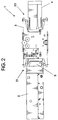
- FIG. 2 a tandem relationship of fore and aft grippers 20 and 21, respectively, of the picker assembly 3 is shown.
- the fore gripper 20 faces the magazine 4, and the aft gripper 21 faces the storage device 2.
- the tandem relationship of the fore gripper 20 to the aft gripper 21 enables a data cassette to "pass-thru" the picker assembly 3, hence the picker assembly 3 operates a pass-thru picker.
- Both the fore and aft grippers 20, 21 extend beyond an envelope of the data cassettes 5 when a data cassette 5 is present on either side of the picker assembly 3.
- the fore and aft grippers 20, 21 For the picker assembly to be translated, the fore and aft grippers 20, 21 must be in an open position (as shown) to avoid an interference with any residing data cassettes 5. Note that by operating the fore and aft grippers 20, 21 independently, a distance separating the magazine 4 from the storage device 2 can be minimized since the fore gripper 21 can be held open except when grabbing a data cassette 5. Additionally, there is no need to translate the.picker assembly perpendicular to the storage device 2 and the magazine 4.
- the appropriate fore or aft gripper 20, 21 In order to retrieve a data cassette 5 from the magazine 4 or the storage device 2, the appropriate fore or aft gripper 20, 21 must close and contact the given data cartridge.
- the picker assembly 3 described herein allows for the fore and aft grippers 20, 21 to operate independently, i.e., the fore gripper 20 can be maintained in an open position while the aft gripper 21 is actuated open or closed, or vice versa.
- a benefit realized by independent gripper operation is that a given data cassette can be retrieved or returned by the picker assembly 3 without disturbing other data cassettes 5.
- a side 31 of the magazine 4 extends beyond a main body of the magazine 4 having a length approximating the length of a data cassette 5 and providing guidance features (not shown) for guiding the magazine 4 into the storage subsystem 1.
- a divider 36 is shown which provides a partial wall separating one storage cell from another and extending between a top 35 and a bottom 32 of the magazine 4.
- the bottom 32 includes a plurality of cantilevers 37, one for each storage cell.
- Each cantilever further includes a tab or cassette retention feature 38 (hereinafter referred to as tab 38) which mates or cooperates with one of the two retention indentations 8, 9 (import and export indentations) with each data cassette 5.
- the cantilever 37 as shown in FIG. 3 is in a "cassette locked" position, that is, the tab 38 mates with a cassette retention indentation 9 (FIG. 1) to lockably hold the data cassette 5 in the storage cell.
- the cantilever 37, and hence the tab 38, is held in place, which is upward into a data cassette 5 retention indentation, by a lock plate 33 which has a plurality of lock bars 39, one lock bar 39 for each cantilever 37.
- the lock plate 33 is slidable into one of two predetermined positions, a magazine interlocked and a magazine non-interlocked position, wherein in the magazine non-interlocked position the lock plate 33 not only locks the data cassettes 5 into respective storage cells, but the lock plate 33 also interfaces with a bottom plate 34 such that the magazine 4 can be inserted to or removed from the storage subsystem 1 (magazine non-interlocked position).
- the bottom plate 34 functionally holds the lock plate 33 slidably, and with a spring bias, below bottom 32.
- magazine non-interlocked may be used interchangeably with the term “cassette locked” as these terms refer to a like position of the lock plate 33, but wherein the former term is more descriptive of a relationship between the magazine 4 and the storage subsystem 1 and the latter term is more descriptive of a relationship between the magazine 4 and the data cassettes 5.
- term “magazine interlocked” may be used interchangeably with the term “cassette unlocked” as these terms also refer to a like but different position of the lock plate 33, and again wherein the former term is more descriptive of a relationship between the magazine 4 and the storage subsystem 1 and the latter term is more descriptive of a relationship between the magazine 4 and the data cassettes 5.
- FIG. 4 depicts a like cut-away side view of the magazine 4 but with the lock plate 33 slid into the cassette unlocked or magazine interlocked position.
- the lock plate In the cassette unlocked position, the lock plate is aligned such that each lock bar 39 (not shown due to cut away) is located not directly below but below and to a side of each corresponding cantilever 37, and instead an opening or void is located substantially below each tab 38.
- each tab 38 via the cantilever 37 and pressure from a data cassette 5, is easily pushed downward into the void such that each data cassette 5 can be easily removed from the magazine 4.
- the data cassettes 5 are releasably held in the magazine 4.
- the locking plate 33 and the bottom 34 cooperate to form an "interlock" for securing the magazine 4 to the storage subsystem 1.
- FIG.s 5 and 6 show a bottom and top side, respectively, of the locking plate 33 in greater detail.
- two spring members 51 and 52 which are molded as part of the lock plate 33, are located for springably biasing the lock plate 33 relative to the cantilevers 37 (FIG. 3), for example, in the magazine non-interlocked position.
- a manual lock tab 54 is provided for allowing an operator a method to manually slide the lock plate 33 against the spring bias and into the cassette unlocked position.
- the molded spring members 51, 52 may fail or break prematurely.
- metal springs can be used instead of the molded spring members 51, 52 that attach to the bottom plate and push against the lock plate 33 for providing the desired spring bias.
- FIG. 5 additionally shows the plurality of openings or voids 56 which allow the cantilevers 37 to recede away from the data cassettes 5 for easy insertion or removal.
- a groove 53 is provided which cooperates with the bottom 34 (FIG. 3) for forming an interlock feature to interlock the magazine 4 to the storage subsystem 1.
- the top side of the lock plate 33 shows the relationship of the openings 56 to the lock bars 39.
- Each lock bar 39 is provided with a safety ramp 57 which slopes inward from bottom to top towards the lock bar 39.
- the safety ramp 57 will guide the failed cantilever 37 up into the corresponding data cassette 5 retention indentation thus allowing the lock bar 33 to be slid into its desired position.
- FIG. 7 is a bottom view of the magazine 4 having the bottom plate 34 removed therefrom for exposing the lock plate 33.
- the lock plate 33 is shown in the spring biased cassette locked position. In the cassette locked position the tabs 38 are supported above corresponding lock bars 34 and are thus only partially visible. Additionally, the spring members 51 and 52 are applying a bias pressure against the bottom 32 for holding the lock plate 33 in position.
- Manual lock tab 54 can be grasped for sliding the lock plate 33 into the cassette unlocked position for releasing data cassettes 5. The groove 53 is moved with the manual lock tab 54 which creates and/or releases the interlock with the storage subsystem 1 as will become apparent.
- FIG. 8 is a bottom view of the magazine 4 also having the bottom plate 34 removed for exposing the lock plate 33, but in this instance with the lock plate 33 is in the cassette unlocked position.
- a bottom side of tabs 38 can be seen through openings 56 wherein the tabs 38 are free to move down into openings 56 to allow data cassettes to easily slide over the tabs 38.
- the spring members 51 and 52 have an external force applied thereto either by the manual lock tab 54 or by an interface at the storage subsystem 1.
- the groove 53 is in the interlocked position but the interlock itself is formed in combination with the removed bottom 34.
- FIG. 9 provides a perspective view of the magazine 4 from a bottom orientation.
- the groove 53 and manual lock tab 54 interface with bottom 34 for forming the interlock.
- the lock plate 33 is shown in the magazine non-interlocked position wherein an open path is formed from the groove 53 to an edge of the bottom 34 such that a pin (not shown), for example, of the storage subsystem 1 can slide therethrough.
- the actual interlock is formed by closing off the open path.
- a relationship of the plurality of dividers 36 can be more clearly seen for forming the plurality of storage cells.
- Guide features can also be seen on edge 31 for assisting guidance of the magazine 4 into and out of the storage subsystem 1.
- a cassette present sensor slot 55 is provided so that storage subsystem 1 is able to sense a manual insertion of a cassette 5 into a priority storage slot for priority processing.
- This present sensor slot 55 can alternately be located on a side 31 without departing from the present sensing function. While the storage cells are substantially shorter in length than a length of the data cassette 5, the edges 31 are substantially the same length thereby offering protection to data cassettes 5 stored in end storage cells. Additionally, edges 31 provide sensor obstructions for positioning the picker assembly 3.
- FIG. 10 provides a perspective view of the magazine 4 from a bottom orientation wherein the groove 53 and manual lock tab 54 are slid into the magazine interlocked position.
- the manual lock tab 54 now blocks the open path such that a pin held in groove 53 is interlocked with the bottom plate 54 and the magazine 4 is prevented from being removed from the storage subsystem 1. Having slid the lock plate 33 into the magazine interlocked position unlocks the data cassettes 5 as previously described.
- the function of the picker assembly 3 is to transfer a data cassette 5 from the magazine 4 to the storage device 2, and subsequently return the data cassette 5 to the originating storage cell within the magazine 4.
- the magazine 4 can be loaded with data cassettes 5 by an operator by sliding the manual lock tab 54 into the cassette unlock position. Typically, less than 300 grams of.force is required to overcome the spring bias force applied by the spring members 51, 52. Having loaded the magazine 4, the manual lock tab 54 is released thus locking the cassettes 4 into the storage cells of the magazine 4. The magazine 4 can now be inserted into the storage subsystem 1.
- Inserting the magazine 4 causes the groove 53 and bottom plate 34 to interact with the storage subsystem 1 such that the lock plate 34 is again pushed into the magazine interlocked position so that the magazine 4 is locked in place and the data cassettes 4 are now releasably held in the storage cells.
- the operation sequence begins when a request is sent to the automated storage subsystem 1 to load into the storage device 2 a specific data cassette 5 located within the magazine 4.
- the initial state of the picker is with the fore gripper 20 and the aft gripper 21 both in the open position, allowing the picker assembly to freely traverse the magazine 4.
- the accessor 6 will translate the picker assembly to be in line with the storage cell known to contain the requested data cassette 5.
- the requested data cassette which is releasably held in the magazine 4 in an import position (reachable by the fore gripper 20) can be gripped and removed from the magazine 4 and loaded into the loader slot 2 for processing.
- the aft gripper 21 removes the data cassette 5 from the storage slot.
- the processed data cassette 5 is returned to its original storage cell or to an empty storage cell by the fore gripper 20.
- the processed data cassette 5 is ejected by the fore gripper 20 back into the storage cell such that the processed data cassette 5, for example, is now in an export position, that is, the cassette export retention indentation 8 is aligned above the tab 38.
- a data cassette 5 in an export position is out of reach of the fore gripper 20.
- FIG. 11 depicts a cassette 5 loaded in both an import and an export position.
- the fore gripper 20 is able to push the data cassette 5 out of its own reach since a top edge of the data cassette 5 is longer than a bottom edge and the top finger of the fore gripper is able to push the data cassette 5 away by the top edge thereof.
- Processed data cassettes 5 are visible to the operator by virtue of being returned to the export position. At the appropriate time, the operator can disable the interlock between the storage subsystem 1 and the magazine 4 to remove the magazine 4 therefrom for retrieving the processed data cartridges. At this time the processed data cassettes 5 are locked into the export positions. If a system error occurs and a data cassette 5 is in a position in the magazine 4 other than an import or export position, the tab 38 will block a corresponding lock bar 39 such that the lock plate 33 will be prevented from sliding back into the magazine non-interlocked position thus preventing magazine removal until the error is corrected.
- an automated storage subsystem for randomly selecting one cassette from a plurality of cassettes held in a pass-thru cassette magazine and transporting the selected cassette therefrom to a storage device.
- the automated storage subsystem includes the storage device for receiving the selected cassette for retrieving data therefrom and/or storing data thereto.
- Each cassette has first and second retention features spaced apart and aligned on an edge thereof.
- the pass-thru cassette magazine is retained in the automated storage subsystem in a magazine interlocked position while the plurality of cassettes are maintained in the pass-thru cassette magazine in a cassette unlocked state for removal therefrom and return thereto by the picker mechanism.
- the pass-thru cassette magazine maintains the plurality of cassettes in a cassette locked state when the pass-thru cassette magazine is released from said automated storage subsystem.
- the pass-thru cassette magazine includes a housing having first and second sides, a top and a bottom, and a plurality of dividers substantially equally spaced apart between the first and second sides for defining a plurality of storage cells.
- the housing is open at a front and a back for allowing each cassette to pass through each storage cell, wherein the storage cells are substantially shorter in length than a length of the cassettes.
- the bottom of the housing has a plurality of cantilevers, each cantilever having a cassette retention feature thereon, and wherein each cantilever is positioned at a storage cell location for mating either the first or second cassette retention feature therewith for retaining the corresponding cassette in either the import or export position thereat.
- a locking plate includes upper and lower surfaces and a plurality of locking bars are formed on the upper surface and an interlock feature is formed on the bottom surface.
- the locking plate is slidably held below the housing bottom such that the locking plate is slid into a magazine interlocked position when the pass-thru cassette magazine is loaded into the automated storage subsystem causing each lock bar of the plurality of lock bars to be below and offset from a corresponding cantilever of the plurality of cantilevers, thus releasably holding the plurality of cassettes.
- the locking plate is slid into a magazine non-interlocked position when the pass-thru cassette magazine is removed from said automated storage subsystem such that each lock bar is substantially aligned beneath a corresponding cantilever for locking the cassettes in said storage cells.
- a housing plate attached to the bottom slidably holds the locking plate between the bottom and the housing plate.
Landscapes
- Automatic Tape Cassette Changers (AREA)
- Automatic Disk Changers (AREA)
Applications Claiming Priority (2)
| Application Number | Priority Date | Filing Date | Title |
|---|---|---|---|
| US08/338,838 US5537268A (en) | 1994-11-14 | 1994-11-14 | Multi-function locking mechanism for a multi-celled data cassette magazine |
| US338838 | 1994-11-14 |
Publications (2)
| Publication Number | Publication Date |
|---|---|
| EP0712125A2 true EP0712125A2 (de) | 1996-05-15 |
| EP0712125A3 EP0712125A3 (de) | 1997-01-22 |
Family
ID=23326374
Family Applications (1)
| Application Number | Title | Priority Date | Filing Date |
|---|---|---|---|
| EP95307494A Ceased EP0712125A3 (de) | 1994-11-14 | 1995-10-20 | Kassettenbehälter für automatisches Aufbewahrungsverfahren |
Country Status (3)
| Country | Link |
|---|---|
| US (1) | US5537268A (de) |
| EP (1) | EP0712125A3 (de) |
| JP (1) | JP3245030B2 (de) |
Cited By (15)
| Publication number | Priority date | Publication date | Assignee | Title |
|---|---|---|---|---|
| EP0833332A1 (de) * | 1996-09-25 | 1998-04-01 | Alps Electric Co., Ltd. | Plattenlaufwerk |
| EP0833331A1 (de) * | 1996-09-25 | 1998-04-01 | Alps Electric Co., Ltd. | Plattenmagazin |
| EP0833333A1 (de) * | 1996-09-25 | 1998-04-01 | Alps Electric Co., Ltd. | Plattenmagazin |
| EP0856844A1 (de) * | 1997-02-04 | 1998-08-05 | Eastman Kodak Company | Vorrichtung zum Ver- und Entriegeln von austauschbaren Magazinen in einem Aufzeichnungs-/Wiedergabegerät |
| EP0877361A3 (de) * | 1997-05-09 | 1998-12-16 | Hewlett-Packard Company | Datenkassetten-Behandlungs- und speicherbehälter |
| EP0877367A3 (de) * | 1997-05-09 | 1998-12-16 | Hewlett-Packard Company | Datenkassettenverriegelungs- und -entriegelungssteuersystem |
| EP0877365A3 (de) * | 1997-05-09 | 1998-12-16 | Hewlett-Packard Company | Datenkassetten-zu-Behälter-Referenzierungssystem für Datenkassettenbehandlungsmechanismus in einem automatischen Wechsler |
| EP0877363A3 (de) * | 1997-05-09 | 1998-12-16 | Hewlett-Packard Company | Datenkassettenverriegelungs- und entriegelungssystem |
| EP0877362A3 (de) * | 1997-05-09 | 1998-12-16 | Hewlett-Packard Company | Datenkassetten-Behälter-zu-Lagergestell Ver und -entriegelungssystem |
| US5993045A (en) * | 1997-05-09 | 1999-11-30 | Hewlett-Packard Company | Data cartridge caddy presence sensing method and apparatus |
| WO2000025311A1 (en) * | 1998-10-23 | 2000-05-04 | Storage Technology Corporation | Receiver and magazine assembly for storage library system |
| EP1027704A4 (de) * | 1997-08-12 | 2000-10-11 | Storage Technology Corp | Behälter und magazinzusammenbau für speicherbibliotheksystem |
| EP0867024A4 (de) * | 1996-09-11 | 2000-12-13 | Quatum Corp | Bandkassetten-massenspeicher und -wiederauffindungseinheit mit einer vielzahl von antrieben und magazinen |
| EP1444693A4 (de) * | 2001-10-19 | 2004-12-29 | Spectra Logic Corp | Datenkassettenbibliothek |
| EP1622147A3 (de) * | 2004-07-30 | 2008-03-05 | Tandberg Data ASA | Magnetbandkassettenspeichergerät mit Verriegelungs- und Entriegelungsvorrichtung |
Families Citing this family (20)
| Publication number | Priority date | Publication date | Assignee | Title |
|---|---|---|---|---|
| GB2295047B (en) * | 1994-11-11 | 1998-05-27 | M4 Data Ltd | Autoloader apparatus |
| US5739978A (en) * | 1996-05-17 | 1998-04-14 | Exabyte Corporation | Cartridge handling system with moving I/O drive |
| US5867458A (en) * | 1996-11-22 | 1999-02-02 | Breece Hill Technologies, Inc. | Magazine for holding computer data storage cartridges |
| US5815340A (en) * | 1996-11-25 | 1998-09-29 | Breece Hill Technologies, Inc. | Apparatus and methods for cartridge retrieval and insertion in a storage library subsystem including a robotic shuttle having a sole rocker beam |
| US5936795A (en) * | 1997-03-05 | 1999-08-10 | Seagate Technology, Inc. | Magazine cassette locking device |
| US6493178B1 (en) * | 1997-04-30 | 2002-12-10 | Spectra Logic Corporation | Data cartridge library system |
| US6533522B1 (en) * | 1998-06-10 | 2003-03-18 | International Business Machines Corporation | Bi-directional magazine and trays for storage media |
| JP2001052398A (ja) * | 1999-08-04 | 2001-02-23 | Fujitsu Ltd | 装填装置 |
| US6424111B1 (en) | 2000-11-10 | 2002-07-23 | Breece Hill Technologies, Inc. | Robotic library design for a storage cartridge pick and place mechanism |
| US6560061B2 (en) * | 2001-01-04 | 2003-05-06 | Qualstar Corporation | High density tape library system |
| US6804078B2 (en) | 2001-07-19 | 2004-10-12 | International Business Machines Corporation | Apparatus and method to expedite data access from a portable data storage cartridge |
| US6909577B2 (en) * | 2002-06-07 | 2005-06-21 | Hewlett-Packard Development Company, L.P. | Low-overhead storage magazine |
| TWI271716B (en) * | 2004-10-18 | 2007-01-21 | Lite On It Corp | Optical disc drive |
| JP2007080440A (ja) * | 2005-09-15 | 2007-03-29 | Mitsumi Electric Co Ltd | テープカートリッジオートローダー |
| US7474497B2 (en) * | 2006-03-14 | 2009-01-06 | International Business Machines Corporation | Deep slot magazine storage library |
| JP5540844B2 (ja) | 2010-04-06 | 2014-07-02 | 富士通株式会社 | 制御プログラム、制御方法および制御装置 |
| US9717158B2 (en) | 2014-02-13 | 2017-07-25 | Hewlett Packard Enterprise Development Lp | Handle mechanism |
| US9093088B1 (en) * | 2014-05-14 | 2015-07-28 | International Business Machines Corporation | Load balancing and space efficient big data tape management |
| US9854698B2 (en) | 2014-06-20 | 2017-12-26 | Hewlett Packard Enterprise Development Lp | Support member |
| US11574656B2 (en) * | 2020-02-13 | 2023-02-07 | International Business Machines Corporation | Automated tape library deep slot protection |
Citations (3)
| Publication number | Priority date | Publication date | Assignee | Title |
|---|---|---|---|---|
| US4929861A (en) | 1988-12-19 | 1990-05-29 | Metcalf Darrell J | Quick release latching and dispensing device |
| US5004393A (en) | 1989-09-29 | 1991-04-02 | Storage Technology Corporation | Autoloader magazine for tape cartridges and method therefor |
| US5247406A (en) | 1991-07-30 | 1993-09-21 | Storage Technology Corporation | Tape cartridge magazine |
Family Cites Families (11)
| Publication number | Priority date | Publication date | Assignee | Title |
|---|---|---|---|---|
| NL144080B (nl) * | 1968-05-10 | 1974-11-15 | Matsushita Electric Industrial Co Ltd | Bandcassettewisselaar. |
| JPS6361482A (ja) * | 1986-09-01 | 1988-03-17 | Fujitsu Ltd | カ−トリツジマガジン |
| JPH0634325B2 (ja) * | 1987-04-27 | 1994-05-02 | 株式会社日立製作所 | カ−トリツジ・マガジン |
| US5021902A (en) * | 1988-02-17 | 1991-06-04 | Hitachi, Ltd. | Tape changer for loading and unloading a magazine of magnetic tape cartridges |
| CH675644A5 (de) * | 1988-03-14 | 1990-10-15 | Ascom Autelca Ag | |
| EP0392620A3 (de) * | 1989-04-13 | 1992-07-01 | Koninklijke Philips Electronics N.V. | Gerät für den automatischen Zugriff auf Kassetten in einem Magazin |
| US5153862A (en) * | 1989-11-06 | 1992-10-06 | North American Philips Corporation | Cassette for storing, moving and loading optical storage disk cartridges |
| US5264974A (en) * | 1991-09-30 | 1993-11-23 | Campbell Kenneth C | Cassette loading system |
| DE4334455C2 (de) * | 1993-02-26 | 1996-09-12 | Fujitsu Ltd | Bibliotheksvorrichtung |
| EP0627738A3 (de) * | 1993-05-27 | 1995-04-26 | Ibm | Magazin zur Speicherung von Kassetten, und Kassettenverarbeitungsvorrichtung. |
| TW257861B (de) * | 1993-08-13 | 1995-09-21 | Ibm |
-
1994
- 1994-11-14 US US08/338,838 patent/US5537268A/en not_active Expired - Fee Related
-
1995
- 1995-10-20 EP EP95307494A patent/EP0712125A3/de not_active Ceased
- 1995-11-07 JP JP28848895A patent/JP3245030B2/ja not_active Expired - Fee Related
Patent Citations (3)
| Publication number | Priority date | Publication date | Assignee | Title |
|---|---|---|---|---|
| US4929861A (en) | 1988-12-19 | 1990-05-29 | Metcalf Darrell J | Quick release latching and dispensing device |
| US5004393A (en) | 1989-09-29 | 1991-04-02 | Storage Technology Corporation | Autoloader magazine for tape cartridges and method therefor |
| US5247406A (en) | 1991-07-30 | 1993-09-21 | Storage Technology Corporation | Tape cartridge magazine |
Cited By (20)
| Publication number | Priority date | Publication date | Assignee | Title |
|---|---|---|---|---|
| EP0867024A4 (de) * | 1996-09-11 | 2000-12-13 | Quatum Corp | Bandkassetten-massenspeicher und -wiederauffindungseinheit mit einer vielzahl von antrieben und magazinen |
| EP0833332A1 (de) * | 1996-09-25 | 1998-04-01 | Alps Electric Co., Ltd. | Plattenlaufwerk |
| EP0833331A1 (de) * | 1996-09-25 | 1998-04-01 | Alps Electric Co., Ltd. | Plattenmagazin |
| EP0833333A1 (de) * | 1996-09-25 | 1998-04-01 | Alps Electric Co., Ltd. | Plattenmagazin |
| EP0856844A1 (de) * | 1997-02-04 | 1998-08-05 | Eastman Kodak Company | Vorrichtung zum Ver- und Entriegeln von austauschbaren Magazinen in einem Aufzeichnungs-/Wiedergabegerät |
| EP0877367A3 (de) * | 1997-05-09 | 1998-12-16 | Hewlett-Packard Company | Datenkassettenverriegelungs- und -entriegelungssteuersystem |
| EP0877361A3 (de) * | 1997-05-09 | 1998-12-16 | Hewlett-Packard Company | Datenkassetten-Behandlungs- und speicherbehälter |
| EP0877363A3 (de) * | 1997-05-09 | 1998-12-16 | Hewlett-Packard Company | Datenkassettenverriegelungs- und entriegelungssystem |
| EP0877362A3 (de) * | 1997-05-09 | 1998-12-16 | Hewlett-Packard Company | Datenkassetten-Behälter-zu-Lagergestell Ver und -entriegelungssystem |
| US5926341A (en) * | 1997-05-09 | 1999-07-20 | Hewlett-Packard Company | Data cartridge interlock and release system |
| US5993045A (en) * | 1997-05-09 | 1999-11-30 | Hewlett-Packard Company | Data cartridge caddy presence sensing method and apparatus |
| US5999500A (en) * | 1997-05-09 | 1999-12-07 | Hewlett-Packard Company | Data cartridge interlock release actuator system |
| US6775093B1 (en) | 1997-05-09 | 2004-08-10 | Hewlett-Packard Development Company, L.P. | Data cartridge-to-caddy referencing system for a data cartridge handling mechanism within an autochanger |
| EP0877365A3 (de) * | 1997-05-09 | 1998-12-16 | Hewlett-Packard Company | Datenkassetten-zu-Behälter-Referenzierungssystem für Datenkassettenbehandlungsmechanismus in einem automatischen Wechsler |
| EP1027704A4 (de) * | 1997-08-12 | 2000-10-11 | Storage Technology Corp | Behälter und magazinzusammenbau für speicherbibliotheksystem |
| US6155659A (en) * | 1998-10-23 | 2000-12-05 | Storage Technology Corporation | Receiver and magazine assembly for storage library system |
| WO2000025311A1 (en) * | 1998-10-23 | 2000-05-04 | Storage Technology Corporation | Receiver and magazine assembly for storage library system |
| EP1444693A4 (de) * | 2001-10-19 | 2004-12-29 | Spectra Logic Corp | Datenkassettenbibliothek |
| EP1622147A3 (de) * | 2004-07-30 | 2008-03-05 | Tandberg Data ASA | Magnetbandkassettenspeichergerät mit Verriegelungs- und Entriegelungsvorrichtung |
| CN1728267B (zh) * | 2004-07-30 | 2011-03-30 | 坦德伯格数据有限公司 | 具有锁定和释放装置的磁带盒存储设备 |
Also Published As
| Publication number | Publication date |
|---|---|
| JP3245030B2 (ja) | 2002-01-07 |
| EP0712125A3 (de) | 1997-01-22 |
| US5537268A (en) | 1996-07-16 |
| JPH08263907A (ja) | 1996-10-11 |
Similar Documents
| Publication | Publication Date | Title |
|---|---|---|
| US5537268A (en) | Multi-function locking mechanism for a multi-celled data cassette magazine | |
| JP3439011B2 (ja) | カートリッジ・フィーダ用マガジン、インターフェース及びこれらを含むシステム | |
| EP0494245B1 (de) | Magazin für magnetbandkassetten mit selbsttätiger ladevorrichtung sowie zugehöriges verfahren | |
| CN102132344B (zh) | 具有多盒深槽单元的自动化数据存储库 | |
| JPH0316059A (ja) | カートリッジアクセス装置 | |
| EP2008277A1 (de) | Verwaltung von datenkassetten in mehrfach-kassettenzellen in einer automatisierten datenspeicherbibliothek | |
| US20070217061A1 (en) | Deep slot magazine storage library | |
| EP1239471A2 (de) | Kassettenhandhabungsvorrichtung mit einer automatischen Schublade | |
| JPH05189850A (ja) | カートリッジライブラリ装置 | |
| US5418664A (en) | Indexing hand for robotic storage library | |
| US7855938B2 (en) | Expandable data storage system and method with cartridge pass-through between cartridge handling units | |
| EP0877363B1 (de) | Datenkassettenverriegelungs- und entriegelungssystem | |
| EP0877362B1 (de) | Datenkassetten-Behälter-zu-Lagergestell Ver- und -entriegelungssystem | |
| US5927834A (en) | Receiver and magazine assembly for storage library system | |
| US6549358B1 (en) | Ehanced gripper for transporting cartridges in an information storage library | |
| EP0877364A2 (de) | Datenkassettenbehälteranwesenheitsüberprüfungsverfahren und -gerät | |
| EP0877367B1 (de) | Datenkassettenverriegelungs- und -entriegelungssteuersystem | |
| US6155659A (en) | Receiver and magazine assembly for storage library system | |
| US8922941B2 (en) | Library apparatus, cartridge, and hand mechanism | |
| EP0877365B1 (de) | Datenkassetten-zu-Behälter-Referenzierungssystem für Datenkassettenbehandlungsmechanismus in einem automatischen Wechsler | |
| US6129427A (en) | Retention array feature for a magazine of a storage library system | |
| EP1150290B1 (de) | Gerät zur Behandlung von Mediakassetten | |
| EP0601247B1 (de) | Greifvorrichtung | |
| EP0877361A2 (de) | Datenkassetten-Behandlungs- und speicherbehälter | |
| JPH1153799A (ja) | 記録媒体の集合収納型カートリッジ取出し装置 |
Legal Events
| Date | Code | Title | Description |
|---|---|---|---|
| PUAI | Public reference made under article 153(3) epc to a published international application that has entered the european phase |
Free format text: ORIGINAL CODE: 0009012 |
|
| AK | Designated contracting states |
Kind code of ref document: A2 Designated state(s): DE FR GB |
|
| 17P | Request for examination filed |
Effective date: 19960914 |
|
| PUAL | Search report despatched |
Free format text: ORIGINAL CODE: 0009013 |
|
| AK | Designated contracting states |
Kind code of ref document: A3 Designated state(s): DE FR GB |
|
| 17Q | First examination report despatched |
Effective date: 19970318 |
|
| GRAG | Despatch of communication of intention to grant |
Free format text: ORIGINAL CODE: EPIDOS AGRA |
|
| STAA | Information on the status of an ep patent application or granted ep patent |
Free format text: STATUS: THE APPLICATION HAS BEEN REFUSED |
|
| 18R | Application refused |
Effective date: 19980912 |