EP0712191A1 - Attache de plafond - Google Patents
Attache de plafond Download PDFInfo
- Publication number
- EP0712191A1 EP0712191A1 EP95117097A EP95117097A EP0712191A1 EP 0712191 A1 EP0712191 A1 EP 0712191A1 EP 95117097 A EP95117097 A EP 95117097A EP 95117097 A EP95117097 A EP 95117097A EP 0712191 A1 EP0712191 A1 EP 0712191A1
- Authority
- EP
- European Patent Office
- Prior art keywords
- profile part
- ceiling
- fixing rail
- fastener
- fastener according
- Prior art date
- Legal status (The legal status is an assumption and is not a legal conclusion. Google has not performed a legal analysis and makes no representation as to the accuracy of the status listed.)
- Granted
Links
- XAGFODPZIPBFFR-UHFFFAOYSA-N aluminium Chemical compound [Al] XAGFODPZIPBFFR-UHFFFAOYSA-N 0.000 claims description 2
- 229910052782 aluminium Inorganic materials 0.000 claims description 2
- 239000004411 aluminium Substances 0.000 claims description 2
- 238000005553 drilling Methods 0.000 description 2
- 238000005516 engineering process Methods 0.000 description 2
- 239000000463 material Substances 0.000 description 2
- 238000010924 continuous production Methods 0.000 description 1
- 230000002349 favourable effect Effects 0.000 description 1
- 239000012467 final product Substances 0.000 description 1
- 238000009434 installation Methods 0.000 description 1
- 238000005304 joining Methods 0.000 description 1
- 238000004519 manufacturing process Methods 0.000 description 1
Images
Classifications
-
- H—ELECTRICITY
- H02—GENERATION; CONVERSION OR DISTRIBUTION OF ELECTRIC POWER
- H02G—INSTALLATION OF ELECTRIC CABLES OR LINES, OR OF COMBINED OPTICAL AND ELECTRIC CABLES OR LINES
- H02G3/00—Installations of electric cables or lines or protective tubing therefor in or on buildings, equivalent structures or vehicles
- H02G3/26—Installations of cables, lines, or separate protective tubing therefor directly on or in walls, ceilings, or floors
- H02G3/263—Installation, e.g. suspension, of conduit channels or other supports
Definitions
- the invention relates to a ceiling fastener arranged to be fastened to the ceiling or the like and arranged to support a shelf structure, especially a ceiling fixing rail holding up cable shelves.
- Ceiling fasteners are nowadays very common in different fields of technology. Ceiling fasteners are used for example to support shelves that hold up cables, i.e. in installations where cables are mounted to travel up near the ceiling or the like.
- the purpose of the invention is to provide a ceiling fastener by means of which the prior art drawbacks can be eliminated.
- the ceiling fastener according to the invention which is characterized in that the ceiling fastener comprises a first profile part and a second profile part, the cross-sectional shape of the second profile part corresponding substantially to the shape of the outer surface of the cross-section of the ceiling fixing rail so that the end of the ceiling fixing rail can be fitted inside the second profile part and that the second profile part is attached to the first profile part by means of mechanical fastening means acting in the axial direction of the second profile part.
- the primary advantage of the invention is that it helps to minimize the number of finishing steps required at the place of assembly.
- the decrease in the number of finishing steps provided by the invention can be illustrated by means of a previously used arrangement wherein eight holes have had to be drilled during the assembly on the site.
- the present invention provides a similar structure as the aforementioned previously known arrangement with no drillings required on the site. The advantages are thus quite essential in practice.
- Another advantage of the invention is that the fastener is inexpensive to produce since both profile parts can be manufactured by the metre so that the costs of a single fastener are very low.
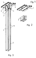
- Reference numeral 1 denotes the first profile part and reference numeral 2 correspondingly denotes the second profile part.
- Reference numeral 3 denotes the ceiling fixing rail.
- the purpose of the above-described structure is to suspend different kinds of shelves, such as cable shelves, from the ceiling or some other corresponding plane.
- the shelves are suspended by attaching ceiling fasteners to the ceiling or the like, and by fastening to the ceiling fasteners ceiling fixing rails on which the shelves are attached.
- the ceiling fastener is formed of a first and a second profile part 1, 2 by attaching the second profile part 2 to the first profile part 1 by means of mechanical fastening means 4 acting in the axial direction of the second profile part 2.
- the second profile part 2 is selected in such a way that its cross-section substantially corresponds to the shape of the outer surface of the cross-section of the ceiling fixing rail 3.
- the second profile part 2 is also designed in such a way that the ceiling fixing rail 3 can be pushed inside the second profile part 2.
- the mechanical fastening means 4 may be for example bolt means.
- Bolt means refer here to bolts, combinations of bolts and nuts, etc. It has been found especially advantageous to adjust the bolt means to extend over the length of the second profile part 2.
- the bolt means can then be advantageously made to press the second profile part 2 against the first profile part 1, while the bolt means rest on the free end of the second profile part.
- a jointing structure that is highly advantageous with respect to tensile strength is thus achieved.
- the first and the second profile part 1, 2 can be produced of any suitable material. It has been found especially advantageous to prepare the profile parts of extruded aluminium profiles, since the profiles can then be manufactured in a continuous process. The extruded profiles are naturally cut to the correct length in a suitable manner.
- the basic idea of the invention is thus that the second profile part 2 is attached to the first profile part by means of an axial bolted joint, thus producing a finished ceiling fastener in an advantageous manner.
- the fastening of the profile parts to each other can be performed advantageously under favourable conditions, and not under the difficult conditions existing normally on the site of assembly.
- the first profile part 1 is naturally provided with holes via which the bolts joining the profile parts can be made to pass through the first profile part 1.
- the ceiling fastener achieved in the aforementioned manner is attached to the ceiling or the like in a suitable manner, for example through bolting.
- the first profile part can also be provided beforehand with holes for the fastening bolts.
- the ceiling fixing rail 3 can be pushed into the second profile part 2 and attached thereto by means of bolts 5 that are transverse with respect to the axial direction of the second profile part 2.
- the second profile part 2 is also provided beforehand with holes for the bolts 5.
- Corresponding holes are also provided in the ceiling fixing rail 3.
- Providing the entire length of the ceiling fixing rail with holes 6 ensures that the rail can be freely cut at a desired point without any problems occurring in the fastenings.
Landscapes
- Engineering & Computer Science (AREA)
- Architecture (AREA)
- Civil Engineering (AREA)
- Structural Engineering (AREA)
- Mutual Connection Of Rods And Tubes (AREA)
- Seats For Vehicles (AREA)
- Thin Film Transistor (AREA)
- Residential Or Office Buildings (AREA)
- Vehicle Interior And Exterior Ornaments, Soundproofing, And Insulation (AREA)
- Assembled Shelves (AREA)
- Joining Of Building Structures In Genera (AREA)
Applications Claiming Priority (2)
| Application Number | Priority Date | Filing Date | Title |
|---|---|---|---|
| FI945297 | 1994-11-10 | ||
| FI945297A FI96910C (fi) | 1994-11-10 | 1994-11-10 | Kattokiinnitin |
Publications (2)
| Publication Number | Publication Date |
|---|---|
| EP0712191A1 true EP0712191A1 (fr) | 1996-05-15 |
| EP0712191B1 EP0712191B1 (fr) | 1999-01-13 |
Family
ID=8541773
Family Applications (1)
| Application Number | Title | Priority Date | Filing Date |
|---|---|---|---|
| EP95117097A Expired - Lifetime EP0712191B1 (fr) | 1994-11-10 | 1995-10-30 | Attache de plafond |
Country Status (4)
| Country | Link |
|---|---|
| EP (1) | EP0712191B1 (fr) |
| AT (1) | ATE175820T1 (fr) |
| DE (1) | DE69507263T2 (fr) |
| FI (1) | FI96910C (fr) |
Cited By (4)
| Publication number | Priority date | Publication date | Assignee | Title |
|---|---|---|---|---|
| DE10216112C2 (de) * | 2001-05-10 | 2003-12-04 | Zurecon Ag Zuerich | Montageeinheit für die Installationstechnik sowie aus mehreren solchen Montageeinheiten gebildete Installationsanlage |
| EP1589626A1 (fr) * | 2004-04-19 | 2005-10-26 | Vergokan | Ensemble de suspension obtenu par montage par encliquetage pour chemins de câbles |
| DE102024124552B3 (de) * | 2024-08-28 | 2025-09-04 | Obo Bettermann Hungary Kft | Befestigungsanordnung zwischen einem Halter und einer Kabeltragkomponente sowie Halter mit einem daran angeschlossenen Anschlussadapter |
| EP4708596A1 (fr) | 2024-08-27 | 2026-03-11 | OBO Bettermann Hungary Kft | Support avec adaptateur de connexion attaché à celui-ci et ensemble de fixation comprenant un tel support |
Citations (3)
| Publication number | Priority date | Publication date | Assignee | Title |
|---|---|---|---|---|
| EP0108222A2 (fr) * | 1982-11-04 | 1984-05-16 | Rieth & Co. GmbH | Structure de support |
| DE9108822U1 (de) * | 1991-07-18 | 1991-09-12 | OBO Bettermann oHG, 5750 Menden | Vorrichtung zur hängenden Halterung von Kabeln u.dgl. Langformteilen an Gebäudedecken |
| DE4137618A1 (de) * | 1991-11-15 | 1993-05-19 | Bettermann Obo Ohg | Vorrichtung zur haengenden halterung von kabeln oder dergleichen langformteilen |
-
1994
- 1994-11-10 FI FI945297A patent/FI96910C/fi active IP Right Grant
-
1995
- 1995-10-30 DE DE69507263T patent/DE69507263T2/de not_active Expired - Fee Related
- 1995-10-30 AT AT95117097T patent/ATE175820T1/de not_active IP Right Cessation
- 1995-10-30 EP EP95117097A patent/EP0712191B1/fr not_active Expired - Lifetime
Patent Citations (3)
| Publication number | Priority date | Publication date | Assignee | Title |
|---|---|---|---|---|
| EP0108222A2 (fr) * | 1982-11-04 | 1984-05-16 | Rieth & Co. GmbH | Structure de support |
| DE9108822U1 (de) * | 1991-07-18 | 1991-09-12 | OBO Bettermann oHG, 5750 Menden | Vorrichtung zur hängenden Halterung von Kabeln u.dgl. Langformteilen an Gebäudedecken |
| DE4137618A1 (de) * | 1991-11-15 | 1993-05-19 | Bettermann Obo Ohg | Vorrichtung zur haengenden halterung von kabeln oder dergleichen langformteilen |
Cited By (4)
| Publication number | Priority date | Publication date | Assignee | Title |
|---|---|---|---|---|
| DE10216112C2 (de) * | 2001-05-10 | 2003-12-04 | Zurecon Ag Zuerich | Montageeinheit für die Installationstechnik sowie aus mehreren solchen Montageeinheiten gebildete Installationsanlage |
| EP1589626A1 (fr) * | 2004-04-19 | 2005-10-26 | Vergokan | Ensemble de suspension obtenu par montage par encliquetage pour chemins de câbles |
| EP4708596A1 (fr) | 2024-08-27 | 2026-03-11 | OBO Bettermann Hungary Kft | Support avec adaptateur de connexion attaché à celui-ci et ensemble de fixation comprenant un tel support |
| DE102024124552B3 (de) * | 2024-08-28 | 2025-09-04 | Obo Bettermann Hungary Kft | Befestigungsanordnung zwischen einem Halter und einer Kabeltragkomponente sowie Halter mit einem daran angeschlossenen Anschlussadapter |
Also Published As
| Publication number | Publication date |
|---|---|
| EP0712191B1 (fr) | 1999-01-13 |
| FI96910C (fi) | 1996-09-10 |
| DE69507263T2 (de) | 1999-07-08 |
| DE69507263D1 (de) | 1999-02-25 |
| ATE175820T1 (de) | 1999-01-15 |
| FI96910B (fi) | 1996-05-31 |
| FI945297A0 (fi) | 1994-11-10 |
Similar Documents
| Publication | Publication Date | Title |
|---|---|---|
| US9057542B2 (en) | Snap-on structural connector | |
| US5297888A (en) | Tubular framing system | |
| US6637165B2 (en) | Raised floor system and support apparatus | |
| US3462110A (en) | Support assembly | |
| AU668760B2 (en) | Form panel | |
| US20020175039A1 (en) | Escalator support structure | |
| CA3019251A1 (fr) | Interface d'installation destinee a des appareils d'eclairage | |
| US20040055232A1 (en) | Raised floor system and support apparatus | |
| JP2011502859A (ja) | 管を固定するための留め具の設置および取付けの簡略化のための航空機の胴体のセル構造 | |
| EP0712191A1 (fr) | Attache de plafond | |
| US7987948B2 (en) | Length adjustable passenger handle assembly for elevator | |
| CN112031251B (zh) | 一种可调节的圆弧铝方通设计吊顶结构及安装方法 | |
| JP2004270193A (ja) | 化粧パネル材の取付金物及び化粧パネル材の取付金物製造方法 | |
| CN215980305U (zh) | 一种重型承载支架 | |
| CN221073163U (zh) | 一种变截面铝合金装饰条 | |
| US20260015861A1 (en) | Rail suspension system for an integrated ceiling assembly | |
| WO2021030878A1 (fr) | Procédé de fixation | |
| CN220889266U (zh) | 瓦楞铝板拉索式安装系统 | |
| JPH07116781B2 (ja) | 外壁コンクリートパネルの取付け方法 | |
| US20240076867A1 (en) | System and method for forming a wall | |
| EP3870790B1 (fr) | Système de revêtement pour système d'entrée | |
| WO2025247832A1 (fr) | Poutre creuse | |
| CN1225059A (zh) | 两个部件之间的连接系统和模块式部件 | |
| SU1527387A1 (ru) | Сборно-разборна пространственна конструкци | |
| JP2001059298A (ja) | 外壁パネルの取付構造 |
Legal Events
| Date | Code | Title | Description |
|---|---|---|---|
| PUAI | Public reference made under article 153(3) epc to a published international application that has entered the european phase |
Free format text: ORIGINAL CODE: 0009012 |
|
| AK | Designated contracting states |
Kind code of ref document: A1 Designated state(s): AT CH DE FR GB LI NL SE |
|
| 17P | Request for examination filed |
Effective date: 19961024 |
|
| RAP1 | Party data changed (applicant data changed or rights of an application transferred) |
Owner name: NORDIC ALUMINIUM OY |
|
| 17Q | First examination report despatched |
Effective date: 19971031 |
|
| GRAG | Despatch of communication of intention to grant |
Free format text: ORIGINAL CODE: EPIDOS AGRA |
|
| GRAG | Despatch of communication of intention to grant |
Free format text: ORIGINAL CODE: EPIDOS AGRA |
|
| GRAH | Despatch of communication of intention to grant a patent |
Free format text: ORIGINAL CODE: EPIDOS IGRA |
|
| GRAH | Despatch of communication of intention to grant a patent |
Free format text: ORIGINAL CODE: EPIDOS IGRA |
|
| GRAA | (expected) grant |
Free format text: ORIGINAL CODE: 0009210 |
|
| RAP1 | Party data changed (applicant data changed or rights of an application transferred) |
Owner name: NORDIC ALUMINIUM OYJ |
|
| AK | Designated contracting states |
Kind code of ref document: B1 Designated state(s): AT CH DE FR GB LI NL SE |
|
| PG25 | Lapsed in a contracting state [announced via postgrant information from national office to epo] |
Ref country code: SE Free format text: THE PATENT HAS BEEN ANNULLED BY A DECISION OF A NATIONAL AUTHORITY Effective date: 19990113 Ref country code: NL Free format text: LAPSE BECAUSE OF FAILURE TO SUBMIT A TRANSLATION OF THE DESCRIPTION OR TO PAY THE FEE WITHIN THE PRESCRIBED TIME-LIMIT Effective date: 19990113 Ref country code: LI Free format text: LAPSE BECAUSE OF FAILURE TO SUBMIT A TRANSLATION OF THE DESCRIPTION OR TO PAY THE FEE WITHIN THE PRESCRIBED TIME-LIMIT Effective date: 19990113 Ref country code: FR Free format text: LAPSE BECAUSE OF FAILURE TO SUBMIT A TRANSLATION OF THE DESCRIPTION OR TO PAY THE FEE WITHIN THE PRESCRIBED TIME-LIMIT Effective date: 19990113 Ref country code: CH Free format text: LAPSE BECAUSE OF FAILURE TO SUBMIT A TRANSLATION OF THE DESCRIPTION OR TO PAY THE FEE WITHIN THE PRESCRIBED TIME-LIMIT Effective date: 19990113 |
|
| REF | Corresponds to: |
Ref document number: 175820 Country of ref document: AT Date of ref document: 19990115 Kind code of ref document: T |
|
| REG | Reference to a national code |
Ref country code: CH Ref legal event code: EP |
|
| REF | Corresponds to: |
Ref document number: 69507263 Country of ref document: DE Date of ref document: 19990225 |
|
| EN | Fr: translation not filed | ||
| NLV1 | Nl: lapsed or annulled due to failure to fulfill the requirements of art. 29p and 29m of the patents act | ||
| REG | Reference to a national code |
Ref country code: CH Ref legal event code: PL |
|
| PLBE | No opposition filed within time limit |
Free format text: ORIGINAL CODE: 0009261 |
|
| STAA | Information on the status of an ep patent application or granted ep patent |
Free format text: STATUS: NO OPPOSITION FILED WITHIN TIME LIMIT |
|
| 26N | No opposition filed | ||
| REG | Reference to a national code |
Ref country code: GB Ref legal event code: IF02 |
|
| PGFP | Annual fee paid to national office [announced via postgrant information from national office to epo] |
Ref country code: GB Payment date: 20021004 Year of fee payment: 8 |
|
| PGFP | Annual fee paid to national office [announced via postgrant information from national office to epo] |
Ref country code: AT Payment date: 20021018 Year of fee payment: 8 |
|
| PGFP | Annual fee paid to national office [announced via postgrant information from national office to epo] |
Ref country code: DE Payment date: 20021022 Year of fee payment: 8 |
|
| PG25 | Lapsed in a contracting state [announced via postgrant information from national office to epo] |
Ref country code: GB Free format text: LAPSE BECAUSE OF NON-PAYMENT OF DUE FEES Effective date: 20031030 Ref country code: AT Free format text: LAPSE BECAUSE OF NON-PAYMENT OF DUE FEES Effective date: 20031030 |
|
| PG25 | Lapsed in a contracting state [announced via postgrant information from national office to epo] |
Ref country code: DE Free format text: LAPSE BECAUSE OF NON-PAYMENT OF DUE FEES Effective date: 20040501 |
|
| GBPC | Gb: european patent ceased through non-payment of renewal fee |
Effective date: 20031030 |