EP0712686A1 - Rail de guidage - Google Patents
Rail de guidage Download PDFInfo
- Publication number
- EP0712686A1 EP0712686A1 EP95114365A EP95114365A EP0712686A1 EP 0712686 A1 EP0712686 A1 EP 0712686A1 EP 95114365 A EP95114365 A EP 95114365A EP 95114365 A EP95114365 A EP 95114365A EP 0712686 A1 EP0712686 A1 EP 0712686A1
- Authority
- EP
- European Patent Office
- Prior art keywords
- guide rail
- suction box
- rail according
- underside
- guide
- Prior art date
- Legal status (The legal status is an assumption and is not a legal conclusion. Google has not performed a legal analysis and makes no representation as to the accuracy of the status listed.)
- Withdrawn
Links
- 238000007789 sealing Methods 0.000 claims abstract description 5
- 239000006260 foam Substances 0.000 description 15
- 229920001971 elastomer Polymers 0.000 description 6
- 229920002635 polyurethane Polymers 0.000 description 2
- 239000004814 polyurethane Substances 0.000 description 2
- 239000002023 wood Substances 0.000 description 2
- 206010041662 Splinter Diseases 0.000 description 1
- 229910003460 diamond Inorganic materials 0.000 description 1
- 239000010432 diamond Substances 0.000 description 1
- 238000007654 immersion Methods 0.000 description 1
- 239000000463 material Substances 0.000 description 1
- 239000007787 solid Substances 0.000 description 1
- 239000004575 stone Substances 0.000 description 1
Images


Classifications
-
- B—PERFORMING OPERATIONS; TRANSPORTING
- B23—MACHINE TOOLS; METAL-WORKING NOT OTHERWISE PROVIDED FOR
- B23Q—DETAILS, COMPONENTS, OR ACCESSORIES FOR MACHINE TOOLS, e.g. ARRANGEMENTS FOR COPYING OR CONTROLLING; MACHINE TOOLS IN GENERAL CHARACTERISED BY THE CONSTRUCTION OF PARTICULAR DETAILS OR COMPONENTS; COMBINATIONS OR ASSOCIATIONS OF METAL-WORKING MACHINES, NOT DIRECTED TO A PARTICULAR RESULT
- B23Q9/00—Arrangements for supporting or guiding portable metal-working machines or apparatus
- B23Q9/0014—Portable machines provided with or cooperating with guide means supported directly by the workpiece during action
- B23Q9/0042—Portable machines provided with or cooperating with guide means supported directly by the workpiece during action the guide means being fixed only on the workpiece
Definitions
- Guide rails are known in practice, for example to guide circular saws. Despite the manual feed, this should result in an exactly straight saw cut that is in the right place.
- the guide rail is an elongated plate, on the top of which the circular saw slides.
- the underside of the guide rail is covered with foam strips, which should give the guide rail a largely secure hold on the workpiece when they rest on the workpiece.
- a rib running over its length is provided on the top of the guide rail and is overlapped by a groove formed in the base plate of the tool. As a result, the tool is guided virtually free of play across the rib.
- the foam strips are not always sufficient to secure the guide rail on the workpiece so that it does not slip.
- the handling of the screw clamp itself is inconvenient. With it the one arm can be moved along the screw clamp rail in the usual way and is held by jamming. Slight vibrations during handling cause the movable arm to slide down on the screw clamp rail.
- the guide rail With the help of the vacuum box on the underside of the guide rail, the guide rail is securely attached to the workpiece. Until the vacuum is switched on, the guide rail can be moved essentially freely on the workpiece. As soon as the correct position is reached, the vacuum is switched on, whereby the guide rails are fixed immovably. No other tools need to be used for this. In particular, it is no longer necessary to reach under the workpiece, which always entails the risk of displacing the guide rail from its desired position.
- the bearing surface is formed by at least two strips running parallel and at a distance from one another.
- the strips can be part of the sealing edge represent the vacuum box, whereby the overall height of the guide rail is particularly low, so that the immersion depth of the tool can be used to the maximum.
- Further walls of the vacuum box are formed by elastic strips which extend transversely between the strips running in the longitudinal direction.
- the vacuum required for holding is particularly easy to obtain in modern tools by using the suction device that is usually available. Surprisingly, the negative pressure generated by these devices in conjunction with the relatively small area on the underside of the guide rail is sufficient. It is sufficient if the vacuum is connected to the end of the suction hose which is remote from the tool and which connects the tool to the suction device.
- the guide rail according to the invention a particularly space-saving vacuum supply is achieved if the guide rib is used for this purpose, which is tubular for this purpose.
- the length of the vacuum box is smaller than the total length of the guide rail.
- a length of the vacuum box of approximately 40 cm is sufficient.
- the vacuum box is expediently more than half as wide as the guide rail.
- Fig. 1 shows a guide rail 1, on which a hand-held circular saw 2 is placed as an example of a power tool with manual feed.
- the guide rail 1 is used to guide the circular saw 2 exactly straight over a workpiece, not shown, on which the guide rail 1 would rest in order to achieve a precisely straight saw cut.
- the hand-held circular saw 2 is connected in a known manner to a suction device in order to suction off the swarf which arises during sawing.
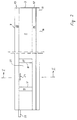
- the guide rail 1 has an elongated straight plate 3 which is rectangular in plan view, which is delimited by an upper side 4, an underside 5 and two longitudinal edges 6, 7 which are parallel to one another.
- the upper side 4 is a sliding surface for a base plate 8 of the hand-held circular saw 2.
- a strip-shaped rib 9 projects from it and extends over the entire length of the guide rail 1.
- the rib 9 has a rectangular cross section and runs parallel to the longitudinal edges 6, 7. The distance of the rib 9 from the longitudinal edge 6 is smaller than the distance to the longitudinal edge 7, next to which the saw blade of the hand-held circular saw 2 would run in use.
- a band-shaped strip 11 made of soft solid rubber runs along the longitudinal edge 7.
- the rubber strip 11, which is glued to the underside 5, protrudes slightly beyond the longitudinal edge 6 and serves as a splinter guard which is cut off to the correct dimension by the circular saw 2 when the guide rail 1 is used for the first time.
- the strip 12 consists of an air-impermeable foam, for example made of polyurethane.
- Another strip 13 of foamed polyurethane lies parallel to the longitudinal edge 7 directly adjacent to it.
- the two foam strips 12 and 13 form with their flat undersides 14 and 15, the contact surface with which the guide rail 1 rests on the respective workpiece.
- the undersides 14 and 15 are therefore also in a common plane in which there is also an edge 16 of the rubber strip 11 which projects freely beyond the longitudinal edge 6 when the guide rail 1 rests on the workpiece in the manner described below.
- a foam strip 17 extending between the foam strips 12 and 13 is provided on the underside 5, which is without a gap and thus largely airtight against the foam strips 12 and 13 abuts.
- the foam strips 17 and 18 have undersides 19 and 20, which lie in the same plane as the undersides 14 and 15.
- the foam strips 12, 13, 17 and 18 delimit a flat shell 21, the bottom of which is that of the foam strips 12, 13 , 17 and 18 enclosed area of the underside 5 of the plate 3.
- the shell 21, the height of which corresponds to the thickness of the foam strips 12, 13, 17 and 18, is a vacuum box.
- the rib 9 contains a channel or passage 22 which begins at a hose connection 23 and extends to the vacuum box 21.
- the underside 5 contains a longitudinal slot 24, via which there is a flow connection between the vacuum box 21 and the channel 22 to the hose connection 23.
- the channel 23 is through an unrecognizable stopper locked. As a result, the vacuum box 21 is only connected to the hose connection 23.
- a suction device 25 is connected via a suction hose 26 to the chip ejection of the circular saw 2.
- the suction hose 26 is only shown schematically.
- a flow connection between the hose connection 23 of the guide rail 1 and the suction side of a suction device 26 is then established via a hose 27 with a clear width of approximately 10 mm.
- the connection point of the hose 27 is in the immediate vicinity of the connection of the suction hose 26 to the suction device 26 in order to be able to take advantage of the negative pressure generated by the air resistance of the suction hose 26.
- the guide rail 1 is positioned on the workpiece in question, in such a way that the edge 16 of the rubber strip 11 projecting beyond the longitudinal edge 6 lies against the desired cut. Then the suction device 25 is switched on, as a result of which a vacuum is created in the vacuum box 21, since the air is sucked out of the vacuum box 21 via the channel 23, the hose connection 26 and the hose 27. As a result, the guide rail 1 can firmly immobilize itself on the workpiece in the region of the vacuum box 21. In this way, it is held on the workpiece without the aid of other clamping tools such as screw clamps. The vacuum at the mouth of the suction device 26 is sufficient to hold.
- the circular saw can 2 can be moved along on the guide rail 1 without moving the guide rail 1.
- the rubber strip 11 lies with its free edge 16 on the workpiece; due to its dimensions and location on the underside 5, it does not impair the sealing effect of the foam strips 12, 13, 17 and 18 on the workpiece.
- a cutting machine equipped with a diamond for example, can also be used.
- the use of the new guide rail is not limited to use in conjunction with wood or wood-based materials.
- the guide rail can also be used in connection with stone, for example.
Landscapes
- Engineering & Computer Science (AREA)
- Mechanical Engineering (AREA)
- Sawing (AREA)
Applications Claiming Priority (2)
| Application Number | Priority Date | Filing Date | Title |
|---|---|---|---|
| DE19944433567 DE4433567C1 (de) | 1994-09-20 | 1994-09-20 | Führungsschiene für ein Handwerkzeug |
| DE4433567 | 1994-09-20 |
Publications (1)
| Publication Number | Publication Date |
|---|---|
| EP0712686A1 true EP0712686A1 (fr) | 1996-05-22 |
Family
ID=6528733
Family Applications (1)
| Application Number | Title | Priority Date | Filing Date |
|---|---|---|---|
| EP95114365A Withdrawn EP0712686A1 (fr) | 1994-09-20 | 1995-09-13 | Rail de guidage |
Country Status (2)
| Country | Link |
|---|---|
| EP (1) | EP0712686A1 (fr) |
| DE (1) | DE4433567C1 (fr) |
Cited By (6)
| Publication number | Priority date | Publication date | Assignee | Title |
|---|---|---|---|---|
| EP1457299A1 (fr) * | 2003-03-10 | 2004-09-15 | Mafell AG | Rail de guidage avec protection des éclats |
| EP2140970A1 (fr) | 2008-07-01 | 2010-01-06 | Mafell AG | Dispositif d'aspiration |
| US10821525B2 (en) | 2018-04-24 | 2020-11-03 | Milwaukee Electric Tool Corporation | Drill stand |
| US12083613B2 (en) | 2022-10-18 | 2024-09-10 | Techtronic Cordless Gp | Track saw including plunge lockout mechanism |
| US12263615B2 (en) | 2020-11-23 | 2025-04-01 | Milwaukee Electric Tool Corporation | Circular saw |
| US12465982B2 (en) | 2022-02-24 | 2025-11-11 | Techtronic Cordless Gp | Track saw including plunge lockout mechanism |
Families Citing this family (2)
| Publication number | Priority date | Publication date | Assignee | Title |
|---|---|---|---|---|
| DE202008000006U1 (de) | 2008-02-14 | 2008-07-10 | Ebert, René | Teleskopartig in ihrer Länge veränderliche Führungsschiene für handbedienbare Maschinen |
| DE102012208148A1 (de) * | 2012-05-15 | 2013-11-21 | Lufthansa Technical Training GmbH | Schablone zur Bearbeitung von Großbauteilen im Flugzeugbau |
Citations (6)
| Publication number | Priority date | Publication date | Assignee | Title |
|---|---|---|---|---|
| US3627436A (en) * | 1970-03-24 | 1971-12-14 | Omark Winslow Co | Tool feeding apparatus |
| FR2285972A1 (fr) * | 1974-09-25 | 1976-04-23 | Cadonati Angelo | Appareil portatif pour le percage des granits, marbres et materiaux similaires |
| US4189268A (en) * | 1978-05-24 | 1980-02-19 | The United States Of America As Represented By The Secretary Of The Navy | Diver-controlled underwater linear milling machine |
| US4324514A (en) * | 1979-03-01 | 1982-04-13 | Mark Craven | Router guide apparatus for cutting printing plates |
| EP0144707A1 (fr) * | 1983-11-12 | 1985-06-19 | FESTO-Maschinenfabrik Gottlieb Stoll | Installation de guidage pour une scie portative |
| DE3906300A1 (de) * | 1989-02-28 | 1990-08-30 | Festo Kg | Fuehrungseinrichtung fuer eine transportable werkzeugmaschine |
-
1994
- 1994-09-20 DE DE19944433567 patent/DE4433567C1/de not_active Expired - Fee Related
-
1995
- 1995-09-13 EP EP95114365A patent/EP0712686A1/fr not_active Withdrawn
Patent Citations (6)
| Publication number | Priority date | Publication date | Assignee | Title |
|---|---|---|---|---|
| US3627436A (en) * | 1970-03-24 | 1971-12-14 | Omark Winslow Co | Tool feeding apparatus |
| FR2285972A1 (fr) * | 1974-09-25 | 1976-04-23 | Cadonati Angelo | Appareil portatif pour le percage des granits, marbres et materiaux similaires |
| US4189268A (en) * | 1978-05-24 | 1980-02-19 | The United States Of America As Represented By The Secretary Of The Navy | Diver-controlled underwater linear milling machine |
| US4324514A (en) * | 1979-03-01 | 1982-04-13 | Mark Craven | Router guide apparatus for cutting printing plates |
| EP0144707A1 (fr) * | 1983-11-12 | 1985-06-19 | FESTO-Maschinenfabrik Gottlieb Stoll | Installation de guidage pour une scie portative |
| DE3906300A1 (de) * | 1989-02-28 | 1990-08-30 | Festo Kg | Fuehrungseinrichtung fuer eine transportable werkzeugmaschine |
Cited By (11)
| Publication number | Priority date | Publication date | Assignee | Title |
|---|---|---|---|---|
| EP1457299A1 (fr) * | 2003-03-10 | 2004-09-15 | Mafell AG | Rail de guidage avec protection des éclats |
| EP2140970A1 (fr) | 2008-07-01 | 2010-01-06 | Mafell AG | Dispositif d'aspiration |
| DE102008031077A1 (de) | 2008-07-01 | 2010-01-07 | Mafell Ag | Saugeinrichtung |
| US10821525B2 (en) | 2018-04-24 | 2020-11-03 | Milwaukee Electric Tool Corporation | Drill stand |
| US11148210B2 (en) | 2018-04-24 | 2021-10-19 | Milwaukee Electric Tool Corporation | Drill stand |
| US11331730B2 (en) | 2018-04-24 | 2022-05-17 | Milwaukee Electric Tool Corporation | Drill stand |
| US11858113B2 (en) | 2018-04-24 | 2024-01-02 | Milwaukee Electric Tool Corporation | Drill stand |
| US12459103B2 (en) | 2018-04-24 | 2025-11-04 | Milwaukee Electric Tool Corporation | Drill stand |
| US12263615B2 (en) | 2020-11-23 | 2025-04-01 | Milwaukee Electric Tool Corporation | Circular saw |
| US12465982B2 (en) | 2022-02-24 | 2025-11-11 | Techtronic Cordless Gp | Track saw including plunge lockout mechanism |
| US12083613B2 (en) | 2022-10-18 | 2024-09-10 | Techtronic Cordless Gp | Track saw including plunge lockout mechanism |
Also Published As
| Publication number | Publication date |
|---|---|
| DE4433567C1 (de) | 1996-04-04 |
Similar Documents
| Publication | Publication Date | Title |
|---|---|---|
| EP2974824B1 (fr) | Système de guidage doté d'une machine-outil portative et rails de guidage | |
| EP0157005A2 (fr) | Dispositif de guidage pour une machine-outil à main | |
| EP3713708B1 (fr) | Guide de travail | |
| EP3703912A1 (fr) | Dispositif auxiliaire de support destiné à un dispositif d'appui de pièce | |
| DE3439739A1 (de) | Werkstueckauflagetisch fuer plattensaegen | |
| WO2009003789A1 (fr) | Machine-outil à main et rail de guidage pour celle-ci | |
| DE3021801C2 (de) | Stichsäge mit am Sägengehäuse befestigbarem Auflagetisch | |
| DE4433567C1 (de) | Führungsschiene für ein Handwerkzeug | |
| EP0479818B1 (fr) | Butee parallele et angulaire | |
| DE102008014470A1 (de) | Sägevorrichtung | |
| DE4037614C1 (en) | Powered guiding appts. for machining workpieces - has positioning stop pivoted to protractor adjustable along guide rail | |
| EP2140970B1 (fr) | Dispositif d'aspriration et système de rail de guidage | |
| EP0674962B1 (fr) | Dispositif pour la coupe en longueur de profilés creux | |
| WO1992013672A1 (fr) | Rail de guidage | |
| DE4029029A1 (de) | Anschlaglineal fuer handkreissaegen | |
| EP2567796A1 (fr) | Poignée | |
| DE10258567B4 (de) | Vorrichtung zur Stanzbearbeitung einer Leiste, insbesondere einer Sockelleiste | |
| AT404572B (de) | Vorrichtung an formatsägemaschinen | |
| EP1358978B1 (fr) | Dispositif pour poinçonner des plinthes, en particulier des plinthes avec un coeur | |
| DE3415796C2 (fr) | ||
| DE19523424A1 (de) | Anschlagvorrichtung für ein Kantenbearbeitungsgerät | |
| DE8034593U1 (de) | Schneidegeraet fuer platten aus schaumkunststoff | |
| EP0070361B1 (fr) | Scie à moteur portative | |
| DE1603815B1 (de) | Einrichtung zum Einstellen der Laenge des einen Eintreibstoessel fuehrenden Mundstuecks eines Handnaglers | |
| DE3137577A1 (de) | Gehrungslade |
Legal Events
| Date | Code | Title | Description |
|---|---|---|---|
| PUAI | Public reference made under article 153(3) epc to a published international application that has entered the european phase |
Free format text: ORIGINAL CODE: 0009012 |
|
| AK | Designated contracting states |
Kind code of ref document: A1 Designated state(s): AT CH DE ES FR GB IT LI SE |
|
| STAA | Information on the status of an ep patent application or granted ep patent |
Free format text: STATUS: THE APPLICATION IS DEEMED TO BE WITHDRAWN |
|
| 18D | Application deemed to be withdrawn |
Effective date: 19961123 |
|
| RAP1 | Party data changed (applicant data changed or rights of an application transferred) |
Owner name: FESTO TOOLTECHNIC KG |