EP0712793A1 - Unterirdischer Tank zum Lagern von Flüssigkeiten bei Raumtemperatur und von unter niedriger Temperatur verflüssigten Gasen - Google Patents
Unterirdischer Tank zum Lagern von Flüssigkeiten bei Raumtemperatur und von unter niedriger Temperatur verflüssigten Gasen Download PDFInfo
- Publication number
- EP0712793A1 EP0712793A1 EP95111987A EP95111987A EP0712793A1 EP 0712793 A1 EP0712793 A1 EP 0712793A1 EP 95111987 A EP95111987 A EP 95111987A EP 95111987 A EP95111987 A EP 95111987A EP 0712793 A1 EP0712793 A1 EP 0712793A1
- Authority
- EP
- European Patent Office
- Prior art keywords
- tank
- filler
- metal structure
- omega
- hot
- Prior art date
- Legal status (The legal status is an assumption and is not a legal conclusion. Google has not performed a legal analysis and makes no representation as to the accuracy of the status listed.)
- Granted
Links
- 239000007788 liquid Substances 0.000 title claims abstract description 19
- 239000007789 gas Substances 0.000 title claims description 17
- 239000000945 filler Substances 0.000 claims abstract description 65
- 229910052751 metal Inorganic materials 0.000 claims abstract description 63
- 239000002184 metal Substances 0.000 claims abstract description 61
- 230000003068 static effect Effects 0.000 claims abstract description 46
- 239000010426 asphalt Substances 0.000 claims abstract description 30
- 239000002689 soil Substances 0.000 claims abstract description 9
- 238000001514 detection method Methods 0.000 claims abstract description 7
- 229920000642 polymer Polymers 0.000 claims abstract description 4
- 239000011796 hollow space material Substances 0.000 claims description 11
- 239000000463 material Substances 0.000 claims description 9
- 239000000654 additive Substances 0.000 claims description 5
- 230000005484 gravity Effects 0.000 claims description 4
- 238000012544 monitoring process Methods 0.000 claims description 4
- 230000035515 penetration Effects 0.000 claims description 4
- 239000000523 sample Substances 0.000 claims description 4
- 239000002174 Styrene-butadiene Substances 0.000 claims description 3
- 230000000996 additive effect Effects 0.000 claims description 3
- MTAZNLWOLGHBHU-UHFFFAOYSA-N butadiene-styrene rubber Chemical compound C=CC=C.C=CC1=CC=CC=C1 MTAZNLWOLGHBHU-UHFFFAOYSA-N 0.000 claims description 3
- BFMKFCLXZSUVPI-UHFFFAOYSA-N ethyl but-3-enoate Chemical compound CCOC(=O)CC=C BFMKFCLXZSUVPI-UHFFFAOYSA-N 0.000 claims description 3
- 238000009434 installation Methods 0.000 claims description 3
- 230000000284 resting effect Effects 0.000 claims description 3
- 239000011115 styrene butadiene Substances 0.000 claims description 3
- 229920003048 styrene butadiene rubber Polymers 0.000 claims description 3
- 230000008719 thickening Effects 0.000 claims description 3
- 230000003993 interaction Effects 0.000 claims description 2
- 239000003381 stabilizer Substances 0.000 claims 1
- 230000008602 contraction Effects 0.000 description 6
- 238000001816 cooling Methods 0.000 description 5
- 238000005260 corrosion Methods 0.000 description 4
- 230000007797 corrosion Effects 0.000 description 4
- 239000011150 reinforced concrete Substances 0.000 description 4
- 230000008901 benefit Effects 0.000 description 2
- 238000010276 construction Methods 0.000 description 2
- 238000007747 plating Methods 0.000 description 2
- 230000002787 reinforcement Effects 0.000 description 2
- 230000000087 stabilizing effect Effects 0.000 description 2
- 230000009471 action Effects 0.000 description 1
- 230000015572 biosynthetic process Effects 0.000 description 1
- 230000006835 compression Effects 0.000 description 1
- 238000007906 compression Methods 0.000 description 1
- 239000012530 fluid Substances 0.000 description 1
- 238000002347 injection Methods 0.000 description 1
- 239000007924 injection Substances 0.000 description 1
- 238000000034 method Methods 0.000 description 1
- 230000010355 oscillation Effects 0.000 description 1
- 238000005192 partition Methods 0.000 description 1
- 238000003466 welding Methods 0.000 description 1
Images


Classifications
-
- F—MECHANICAL ENGINEERING; LIGHTING; HEATING; WEAPONS; BLASTING
- F17—STORING OR DISTRIBUTING GASES OR LIQUIDS
- F17C—VESSELS FOR CONTAINING OR STORING COMPRESSED, LIQUEFIED OR SOLIDIFIED GASES; FIXED-CAPACITY GAS-HOLDERS; FILLING VESSELS WITH, OR DISCHARGING FROM VESSELS, COMPRESSED, LIQUEFIED, OR SOLIDIFIED GASES
- F17C3/00—Vessels not under pressure
- F17C3/005—Underground or underwater containers or vessels
-
- B—PERFORMING OPERATIONS; TRANSPORTING
- B65—CONVEYING; PACKING; STORING; HANDLING THIN OR FILAMENTARY MATERIAL
- B65D—CONTAINERS FOR STORAGE OR TRANSPORT OF ARTICLES OR MATERIALS, e.g. BAGS, BARRELS, BOTTLES, BOXES, CANS, CARTONS, CRATES, DRUMS, JARS, TANKS, HOPPERS, FORWARDING CONTAINERS; ACCESSORIES, CLOSURES, OR FITTINGS THEREFOR; PACKAGING ELEMENTS; PACKAGES
- B65D90/00—Component parts, details or accessories for large containers
- B65D90/02—Wall construction
-
- F—MECHANICAL ENGINEERING; LIGHTING; HEATING; WEAPONS; BLASTING
- F17—STORING OR DISTRIBUTING GASES OR LIQUIDS
- F17C—VESSELS FOR CONTAINING OR STORING COMPRESSED, LIQUEFIED OR SOLIDIFIED GASES; FIXED-CAPACITY GAS-HOLDERS; FILLING VESSELS WITH, OR DISCHARGING FROM VESSELS, COMPRESSED, LIQUEFIED, OR SOLIDIFIED GASES
- F17C2201/00—Vessel construction, in particular geometry, arrangement or size
- F17C2201/01—Shape
- F17C2201/0104—Shape cylindrical
- F17C2201/0119—Shape cylindrical with flat end-piece
-
- F—MECHANICAL ENGINEERING; LIGHTING; HEATING; WEAPONS; BLASTING
- F17—STORING OR DISTRIBUTING GASES OR LIQUIDS
- F17C—VESSELS FOR CONTAINING OR STORING COMPRESSED, LIQUEFIED OR SOLIDIFIED GASES; FIXED-CAPACITY GAS-HOLDERS; FILLING VESSELS WITH, OR DISCHARGING FROM VESSELS, COMPRESSED, LIQUEFIED, OR SOLIDIFIED GASES
- F17C2201/00—Vessel construction, in particular geometry, arrangement or size
- F17C2201/03—Orientation
- F17C2201/035—Orientation with substantially horizontal main axis
-
- F—MECHANICAL ENGINEERING; LIGHTING; HEATING; WEAPONS; BLASTING
- F17—STORING OR DISTRIBUTING GASES OR LIQUIDS
- F17C—VESSELS FOR CONTAINING OR STORING COMPRESSED, LIQUEFIED OR SOLIDIFIED GASES; FIXED-CAPACITY GAS-HOLDERS; FILLING VESSELS WITH, OR DISCHARGING FROM VESSELS, COMPRESSED, LIQUEFIED, OR SOLIDIFIED GASES
- F17C2203/00—Vessel construction, in particular walls or details thereof
- F17C2203/06—Materials for walls or layers thereof; Properties or structures of walls or their materials
- F17C2203/0602—Wall structures; Special features thereof
- F17C2203/0612—Wall structures
- F17C2203/0614—Single wall
- F17C2203/0621—Single wall with three layers
-
- F—MECHANICAL ENGINEERING; LIGHTING; HEATING; WEAPONS; BLASTING
- F17—STORING OR DISTRIBUTING GASES OR LIQUIDS
- F17C—VESSELS FOR CONTAINING OR STORING COMPRESSED, LIQUEFIED OR SOLIDIFIED GASES; FIXED-CAPACITY GAS-HOLDERS; FILLING VESSELS WITH, OR DISCHARGING FROM VESSELS, COMPRESSED, LIQUEFIED, OR SOLIDIFIED GASES
- F17C2203/00—Vessel construction, in particular walls or details thereof
- F17C2203/06—Materials for walls or layers thereof; Properties or structures of walls or their materials
- F17C2203/0634—Materials for walls or layers thereof
- F17C2203/0636—Metals
-
- F—MECHANICAL ENGINEERING; LIGHTING; HEATING; WEAPONS; BLASTING
- F17—STORING OR DISTRIBUTING GASES OR LIQUIDS
- F17C—VESSELS FOR CONTAINING OR STORING COMPRESSED, LIQUEFIED OR SOLIDIFIED GASES; FIXED-CAPACITY GAS-HOLDERS; FILLING VESSELS WITH, OR DISCHARGING FROM VESSELS, COMPRESSED, LIQUEFIED, OR SOLIDIFIED GASES
- F17C2203/00—Vessel construction, in particular walls or details thereof
- F17C2203/06—Materials for walls or layers thereof; Properties or structures of walls or their materials
- F17C2203/0634—Materials for walls or layers thereof
- F17C2203/0678—Concrete
-
- F—MECHANICAL ENGINEERING; LIGHTING; HEATING; WEAPONS; BLASTING
- F17—STORING OR DISTRIBUTING GASES OR LIQUIDS
- F17C—VESSELS FOR CONTAINING OR STORING COMPRESSED, LIQUEFIED OR SOLIDIFIED GASES; FIXED-CAPACITY GAS-HOLDERS; FILLING VESSELS WITH, OR DISCHARGING FROM VESSELS, COMPRESSED, LIQUEFIED, OR SOLIDIFIED GASES
- F17C2209/00—Vessel construction, in particular methods of manufacturing
- F17C2209/22—Assembling processes
- F17C2209/221—Welding
-
- F—MECHANICAL ENGINEERING; LIGHTING; HEATING; WEAPONS; BLASTING
- F17—STORING OR DISTRIBUTING GASES OR LIQUIDS
- F17C—VESSELS FOR CONTAINING OR STORING COMPRESSED, LIQUEFIED OR SOLIDIFIED GASES; FIXED-CAPACITY GAS-HOLDERS; FILLING VESSELS WITH, OR DISCHARGING FROM VESSELS, COMPRESSED, LIQUEFIED, OR SOLIDIFIED GASES
- F17C2221/00—Handled fluid, in particular type of fluid
- F17C2221/03—Mixtures
- F17C2221/032—Hydrocarbons
- F17C2221/035—Propane butane, e.g. LPG, GPL
-
- F—MECHANICAL ENGINEERING; LIGHTING; HEATING; WEAPONS; BLASTING
- F17—STORING OR DISTRIBUTING GASES OR LIQUIDS
- F17C—VESSELS FOR CONTAINING OR STORING COMPRESSED, LIQUEFIED OR SOLIDIFIED GASES; FIXED-CAPACITY GAS-HOLDERS; FILLING VESSELS WITH, OR DISCHARGING FROM VESSELS, COMPRESSED, LIQUEFIED, OR SOLIDIFIED GASES
- F17C2223/00—Handled fluid before transfer, i.e. state of fluid when stored in the vessel or before transfer from the vessel
- F17C2223/01—Handled fluid before transfer, i.e. state of fluid when stored in the vessel or before transfer from the vessel characterised by the phase
- F17C2223/0146—Two-phase
- F17C2223/0153—Liquefied gas, e.g. LPG, GPL
-
- F—MECHANICAL ENGINEERING; LIGHTING; HEATING; WEAPONS; BLASTING
- F17—STORING OR DISTRIBUTING GASES OR LIQUIDS
- F17C—VESSELS FOR CONTAINING OR STORING COMPRESSED, LIQUEFIED OR SOLIDIFIED GASES; FIXED-CAPACITY GAS-HOLDERS; FILLING VESSELS WITH, OR DISCHARGING FROM VESSELS, COMPRESSED, LIQUEFIED, OR SOLIDIFIED GASES
- F17C2223/00—Handled fluid before transfer, i.e. state of fluid when stored in the vessel or before transfer from the vessel
- F17C2223/03—Handled fluid before transfer, i.e. state of fluid when stored in the vessel or before transfer from the vessel characterised by the pressure level
- F17C2223/033—Small pressure, e.g. for liquefied gas
-
- F—MECHANICAL ENGINEERING; LIGHTING; HEATING; WEAPONS; BLASTING
- F17—STORING OR DISTRIBUTING GASES OR LIQUIDS
- F17C—VESSELS FOR CONTAINING OR STORING COMPRESSED, LIQUEFIED OR SOLIDIFIED GASES; FIXED-CAPACITY GAS-HOLDERS; FILLING VESSELS WITH, OR DISCHARGING FROM VESSELS, COMPRESSED, LIQUEFIED, OR SOLIDIFIED GASES
- F17C2250/00—Accessories; Control means; Indicating, measuring or monitoring of parameters
- F17C2250/04—Indicating or measuring of parameters as input values
- F17C2250/0404—Parameters indicated or measured
- F17C2250/0447—Composition; Humidity
- F17C2250/0452—Concentration of a product
-
- F—MECHANICAL ENGINEERING; LIGHTING; HEATING; WEAPONS; BLASTING
- F17—STORING OR DISTRIBUTING GASES OR LIQUIDS
- F17C—VESSELS FOR CONTAINING OR STORING COMPRESSED, LIQUEFIED OR SOLIDIFIED GASES; FIXED-CAPACITY GAS-HOLDERS; FILLING VESSELS WITH, OR DISCHARGING FROM VESSELS, COMPRESSED, LIQUEFIED, OR SOLIDIFIED GASES
- F17C2260/00—Purposes of gas storage and gas handling
- F17C2260/03—Dealing with losses
- F17C2260/035—Dealing with losses of fluid
- F17C2260/037—Handling leaked fluid
-
- F—MECHANICAL ENGINEERING; LIGHTING; HEATING; WEAPONS; BLASTING
- F17—STORING OR DISTRIBUTING GASES OR LIQUIDS
- F17C—VESSELS FOR CONTAINING OR STORING COMPRESSED, LIQUEFIED OR SOLIDIFIED GASES; FIXED-CAPACITY GAS-HOLDERS; FILLING VESSELS WITH, OR DISCHARGING FROM VESSELS, COMPRESSED, LIQUEFIED, OR SOLIDIFIED GASES
- F17C2260/00—Purposes of gas storage and gas handling
- F17C2260/03—Dealing with losses
- F17C2260/035—Dealing with losses of fluid
- F17C2260/038—Detecting leaked fluid
-
- F—MECHANICAL ENGINEERING; LIGHTING; HEATING; WEAPONS; BLASTING
- F17—STORING OR DISTRIBUTING GASES OR LIQUIDS
- F17C—VESSELS FOR CONTAINING OR STORING COMPRESSED, LIQUEFIED OR SOLIDIFIED GASES; FIXED-CAPACITY GAS-HOLDERS; FILLING VESSELS WITH, OR DISCHARGING FROM VESSELS, COMPRESSED, LIQUEFIED, OR SOLIDIFIED GASES
- F17C2260/00—Purposes of gas storage and gas handling
- F17C2260/05—Improving chemical properties
- F17C2260/053—Reducing corrosion
-
- F—MECHANICAL ENGINEERING; LIGHTING; HEATING; WEAPONS; BLASTING
- F17—STORING OR DISTRIBUTING GASES OR LIQUIDS
- F17C—VESSELS FOR CONTAINING OR STORING COMPRESSED, LIQUEFIED OR SOLIDIFIED GASES; FIXED-CAPACITY GAS-HOLDERS; FILLING VESSELS WITH, OR DISCHARGING FROM VESSELS, COMPRESSED, LIQUEFIED, OR SOLIDIFIED GASES
- F17C2270/00—Applications
- F17C2270/01—Applications for fluid transport or storage
- F17C2270/0142—Applications for fluid transport or storage placed underground
- F17C2270/0144—Type of cavity
- F17C2270/0147—Type of cavity by burying vessels
Definitions
- This invention covers an underground tank for storage of liquids of any nature whatsoever, including liquids that are stored at ambient temperature as well as liquid gases to be stored at very low temperature, as LPG.
- tanks are usually cylindrical with horizontal axis and they consist of an internal metal containment structure, an external static facing in plain or reinforced concrete in touch with the soil and a filler located between the metal containment structure and the static facing.
- the metal containment structure is supported by the external plain or reinforced concrete facing by means of - usually insulating - U-bolts and a filler is poured or injected in the hollow space between the metal structure and the static facing.
- the resistance parameters and thickness of the metal structure and of the static facing may be reduced and this in turn will reduce the quantity of material required for the structure.
- the filler after cooling, shall be neither too fluid and deformable nor too compact and rigid.
- the filler shall therefore have adequate viscoelastic characteristics and shall be able to transfer deformation strains from the metal structures to the external facing so that it may actively contribute to the stability of the whole tank while the metal structure will contribute, though to a lesser extent, to withstand the stresses of the surrounding soil on the static facing.
- tank components i.e. the metal structure, filler, static facing and the soil shall mutually interact and form one single structural assembly that defines the stability of the construction work, also in view of seismic stresses.
- Hot blown bitumen was found to be the most suitable filler for this purpose, since it has viscoelastic characteristics when poured or injected in the hollow space through openings in the metal plating that are properly closed after filling. The characteristics of this bitumen are described hereinafter.
- bitumen shall perfectly adhere to the static facing and to the metal structure and shall completely fill all voids between these structures in order to obtain one single structural assembly formed by the external static facing, metal structure, bitumen and surrounding soil .
- the pressure acting on the filler remains however lower in the upper tank zones so that the bitumen may still break away from the static facing and from the metal structure, due to contraction and settling. Furthermore the currently adopted pouring or injection system through openings in the metal structure may cause some difficulties in the upper tank zones.
- these problems are eliminated or at least reduced by fixing a properly spaced and usually electrowelded netting of known type concentrically to the rings of the metal structure.
- the netting is secured to the rings by flats, lengthwise positioned with respect to the tank and welded to the outer ring surface to which the net is welded.
- the netting is embedded in the filler and will act as a stabilizing reinforcement, preventing or at least minimizing contraction of the filler and its detachment from the containment walls according to the objectives of this invention.
- special sections usually round bars , are welded to the omega sections, thus forming channels for drainage of leaks and spills.
- the netting embedded in the filler is also useful if the spacing between the metal structure and static facing is non uniform due to uneveness of the static facing during construction.
- special devices permit the hot filler to be charged into the cavity wall through simple feed bushes or through bushes provided with a charging vessel so as to further complete saturation and a perfect bond of the filler to the metal structure and static facing;
- the charging vessel has also the aim to increase the charging pressure on the filler, especially in the upper part of the tank.
- the filler is let into the hollow space through the evenly spaced feed bushes passing through the central flat portion of the omega shapes.
- omega shapes are fitted with evenly spaced simple feed bushes whereas those provided with a charging vessel are located in the upper part of the tank, always in the central flat section of the omega shape.
- the improved saturation of the filler, its viscoelastic characteristics, its better bond to the static facing and to the metal structure forming the cavity wall also improve tank resistance to seismic strains.
- the transverse channels for detection and drainage of leaking liquids and/or vapor and/or gas are formed, according to this invention, by two parallel and superimposed omega sections welded to the edge of the transverse rings with respect to the tank axis, so that the tank structure can absorb and compensate for any expansion caused by thermal gradients, i.e. the difference between ambient temperature (+20°C) and the temperature required for storage of the liquid gas (at least -45°C). Therefore, free deformation of the rings during temperature variations will be permitted by deflection and expansion of the two omega sections of each transverse channel.
- a liquid and/or vapor and/or gas leak detector is mounted in the lower radial zone of each transverse channel formed by two omega shapes and also by one omega shape and one internal flat. All leak detectors of the transverse channels are linked up to a central monitoring unit so that not only any leakage but also its location are indicated.
- hot blown or simple bitumen to which an additive is added is used as a filler between the metal containment structure and the static facing .
- the filler shall have suitable viscoelastic properties both at ambient and at liquid gas storage temperature.
- polymers such as styrenebutadiene and/or ethylvinylacetate or the like are added to the hot blown or simple bitumen so as to ensure sufficient viscoelasticity of the filler at the above mentioned low temperatures.
- Hot blown bitumen is used as a filler 5 and is hot poured according to known techniques, through small openings that can be closed.
- This filler material i.e. hot blown bitumen, has the aim to transmit the stresses and strains from the metal structure 1 to the static facing 2 and vice-versa; these stresses are due to deformation of the metal structure during filling or emptying of the tank.
- hot-blown bitumen is particularly suitable for this purpose since it has the following average characteristics: - penetration depth at 25°C 10 ⁇ 30 dmm - softening point 80° ⁇ 115°C - Fraas breakpoint - 12 ⁇ + 10°C - ductility at 25°C min 2 cm - flash point min 240°C - specific gravity at 25°/25°C 1.01 ⁇ 1.10 gr/cm3
- this bitumen After cooling down, this bitumen has sufficient viscoelasticity to transfer stresses to the tank components, without causing failure or permanent deformation and the bitumen is pumped into the hollow space at a temperature ranging between 200° and 220°C so as completely to fill the space between the metal structure and the static facing.
- this bitumen may be replaced by other filler material, provided it can be easily poured or injected and meets the above mentioned requirements, has sufficient plasticity to withstand the stresses and strains in the tank components and can protect the outer surface of the metal structure from corrosion.
- a netting 6 is secured to the outer surface of the metal structure 1 with the aim to stabilize the filler 5 and to counteract contraction due to cooling and settlement of the filler while improving its compactedness.
- flat joint plates 7 placed lengthwise with respect to the tank axis are welded onto the metal structure 1, while the netting 6 is welded to these joint plates. The netting thus remains at a certain distance from the metal structure 1 and is embedded in the filler 5.
- the netting 6 is acting, just like reinforced concrete, as a reinforcement of the filler 5 so that any deformations of the metal structure are more easily and directly transmitted to the filler 5 and by the latter to the static facing 2 and vice-versa, thus greatly improving the structural stability of the tank with the cooperation of all its components.
- each ring of the metal structure 1 is completed before it is assembled with the netting 6 so that each ring 1a, 1b, 1c, 1d is provided with the joint plates 7a, 7b, 7c, 7d and its nets 6a, 6b, 6c, 6d.
- the rings are then assembled by partial overlap of the nets welded to the rings 1a, 1b-1c, 1d all located on the same circumference.
- Fig. n°2 and n°5 show the omega shaped transverse channels and related flats 9 forming transverse drainage channels 4 for storage tanks at ambient temperature, as well as the flat 10, 11 forming longitudinal drainage channels. These channels are formed at the edges of the rings 1a, 1b, 1c, 1d which are slightly spaced.
- round bars 12 are lengthwise welded to the omega shapes 8; these round bars 12 are resting on the transverse ends of the nets 6a, 6b, 6c, 6d and are also embedded in the filler 5 in order to provide geometrical continuity of the netting along the omega sections 8 and keep the netting in position, preventing it from coming in touch with the static facing 2 since this contact might cause eddy currents between the static facing 2 and the metal structure 1.
- the netting 6 provides a better bond between the metal structure 1 and the filler 5, counteracting its contraction due to cooling and settlement. It also improves the bond between the filler, the static facing 2 and the metal structure 1.
- the netting may be placed either on the whole tank circumference or only in the upper tank zone according to need.
- an additional load may also be applied to the filler 5 to improve its saturation and adhesion to the walls.
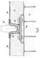
- Fig. 3 shows how hot blown bitumen is charged through the feed bush 13 provided with screw cap 14 through the transverse omega shape 8 onto which the feed bush is welded.
- the hot blown bitumen is pumped through the duct 13' into the feed bush 13 and is distributed according to the arrow F inside the hollow space between the static facing 2 and the metal structure 1, forming superimposed filler layers 5.
- a small length of the flat 9' has to be removed from inside the drain channel 4 so that it will be possible to pour the hot blown bitumen into the cavity wall.
- This flat section is returned to its former position after filling and closing with the screw cap 14.
- Fig. 4 shows the feed bush 15 and screw cap 16, likewise secured and passing through the omega shape 8 as shown in fig. 3, consisting of a vertical pipe length 17 surrounded by a vessel 18 which may have any shape, closed at the top by an end plate 19 and open at the bottom.
- the hot blown bitumen is charged in direction of the arrow F' and remains inside the vessel 18, 19 up to a prefixed bitumen level H determining the load on the material during the charging operation.
- Simple feed bushes 13 are welded onto the omega sections whereas other bushes 15 and the charging vessel 18 are mounted on top of the tank.
- the charging vessel 18 may have any height based upon the load to be applied to the filler during pouring.
- the vessel 18 may also be completely or partially incorporated in the static facing 2.
- the stabilizing netting 6 and/or the use of feed bushes 15 fitted with a charging vessel will permit completely to eliminate or at least to minimize the drawbacks resulting from a poor bond between the bitumen and the upper zones of the metal structure 1 and of the static facing 2, thus ensuring structural continuity of the various tank components, according to the objectives of this invention.
- transverse channels 4 that will permit detection and drainage of any liquid gas leaks.
- These transverse channels 4 are consisting of two omega shapes 21, 22 welded onto the transverse facing edges of two slightly spaced plates 1a-1d, 1b-1c. These omega sections 21, 22 are usually placed in a parallel concentric position, as shown in the drawings.
- transverse channels formed by two omega sections 21, 22 will compensate and absorb the thermal deformations of tanks in which liquid gas will be stored at very low temperature.
- the internal omega shape 22 may also be positioned upside-down as illustrated by the dashes 22' in fig.9. Although this will slightly reduce the tank volume, it still has the advantages deriving from the compression and expansion movements of both omega sections 21, 22 so that strains are better balanced.
- Each transverse channel 4 for detection and drainage of gas leaks is fitted with a leak probe 23 located in the lower radial zone of the channel for easy detection of liquid and/or vapour and/or gas in the channels; all probes 23 of the various transverse channels are linked up to a central monitoring station 24.
- This central monitoring unit 24 will locate any leaks which may thus be promptly eliminated.
- the longitudinal channels consisting of flats 10, 11 welded onto the longitudinal edges of the rings 1a-1b, 1c-1d, are fitted with partitions and are thus linked up to the adjacent transverse sections 4.
- the filler 5 to be used for the low temperature liquid gas storage tanks is a hot blown material injected or poured into the hollow space between the metal plating 1 and the static facing 2, through openings or feed bushes.
- this material shall have a tamping action and shall completely fill and tamp the filler in the hollow space between the metal structure 1 and the static facing 2; it shall have suitable viscoelastic properties to transfer stresses and strains from the metal structure to the static facing and vice-versa, so that all tank components will contribute to the static stability of the tank.
- bitumen whether hot-blown or not, is preferably used as a filler, with additives having the aim to prevent the formation of discontinuities that might be prejudicial to its functions as a filler and to protect from corrosion the metal elements in which the product is stored at low temperature.
- Polymer based additives such as styrenebutadiene and/or ethylvinylacetate are preferable for such corrosion protection based upon their dosage which shall have the aim to extend the Fraas breakpoint from + 10 to -45°C so that the filler will still have a residual viscoelasticity at the minimum temperature limit.
- the plain or hot-blown bitumen will have the following indicatory characteristics: - penetration at 25°C 10 ⁇ 30 dmm - softening point 80 ⁇ 115 °C - Fraas breakpoint + 10° ⁇ -45°C - ductility at 25°C min 2 cm - flash point min 240°C - specific gravity at 25/25°C 1.01 ⁇ 1.10 gr/cm3
- underground tanks for low temperature storage of liquid gases will allow for thermal oscillations causing a deformation of the metal structure in consistency with temperature values ranging from ambient to storage temperatures thus ensuring the maximum stress resisting interaction between the various tank components.
- cylindrical tanks with horizontal axis and with flat or convex heads is also valid for tanks having any other configuration (whether upright, subvertical, spherical etc.).
Landscapes
- Engineering & Computer Science (AREA)
- Mechanical Engineering (AREA)
- General Engineering & Computer Science (AREA)
- Filling Or Discharging Of Gas Storage Vessels (AREA)
Applications Claiming Priority (4)
| Application Number | Priority Date | Filing Date | Title |
|---|---|---|---|
| IT94GE000129 IT1268345B1 (it) | 1994-11-17 | 1994-11-17 | Serbatoio sotterraneo con materiale di riempimento tra paramento statico e struttura metallica stabilizzato con reti e addensato in |
| ITGE940129 | 1994-11-17 | ||
| IT95GE000040 IT1281256B1 (it) | 1995-04-14 | 1995-04-14 | Serbatoio sotterraneo per il contenimento a basse temperature di gas liquefatti |
| ITGE950040 | 1995-04-14 |
Publications (2)
| Publication Number | Publication Date |
|---|---|
| EP0712793A1 true EP0712793A1 (de) | 1996-05-22 |
| EP0712793B1 EP0712793B1 (de) | 1998-03-04 |
Family
ID=26330618
Family Applications (1)
| Application Number | Title | Priority Date | Filing Date |
|---|---|---|---|
| EP95111987A Expired - Lifetime EP0712793B1 (de) | 1994-11-17 | 1995-07-31 | Unterirdischer Tank zum Lagern von Flüssigkeiten bei Raumtemperatur und von unter niedriger Temperatur verflüssigten Gasen |
Country Status (11)
| Country | Link |
|---|---|
| US (1) | US5749675A (de) |
| EP (1) | EP0712793B1 (de) |
| KR (1) | KR960017463A (de) |
| AT (1) | ATE163624T1 (de) |
| AU (1) | AU3457395A (de) |
| BR (1) | BR9505195A (de) |
| CA (1) | CA2156148A1 (de) |
| DE (1) | DE69501709T2 (de) |
| DK (1) | DK0712793T3 (de) |
| ES (1) | ES2113143T3 (de) |
| IL (1) | IL114896A0 (de) |
Cited By (4)
| Publication number | Priority date | Publication date | Assignee | Title |
|---|---|---|---|---|
| GB2296557B (en) * | 1994-12-29 | 1998-11-25 | Ohbayashi Corp | Stabilizing structure of pressure-proof underground constrution |
| EP1304523A3 (de) * | 2001-10-18 | 2004-06-16 | MI.PI S.r.l. | Vorrichtung zur Behandlung von unterirdischen Behälter- und Rohrnetzanlagen |
| WO2009049908A1 (en) * | 2007-10-18 | 2009-04-23 | Eni S.P.A. | Storage system of cryogenic liquids positioned under the seabed |
| EP3091148A4 (de) * | 2013-11-26 | 2017-10-11 | Korea Institute of Geoscience and Mineral Resources (KIGAM) | Hochdruck flüssigkeitsspeicherbehälter und konstruktionsverfahren dafür |
Families Citing this family (3)
| Publication number | Priority date | Publication date | Assignee | Title |
|---|---|---|---|---|
| SE9801994D0 (sv) * | 1998-06-05 | 1998-06-05 | Sydkraft Ab | Anläggning för lagring av naturgas |
| CN106760707B (zh) * | 2016-11-21 | 2019-01-29 | 常州第一建筑集团有限公司 | 地沟异形支口预埋铁施工方法 |
| CN111532603B (zh) * | 2020-05-21 | 2024-05-24 | 集地保温技术(上海)有限公司 | 利于罐体泄露气体监控、回收的低温绝缘保温系统 |
Citations (2)
| Publication number | Priority date | Publication date | Assignee | Title |
|---|---|---|---|---|
| EP0325683A2 (de) | 1988-01-29 | 1989-08-02 | ING. NINO FERRARI -Impresa Costruzioni Generali S.r.l. | Unterirdischer Grosstank mit einer durch die gegenseitige Beeinflussung von Metallgehäuse, Betonverkleidung und Zwischenraumfüllung vorgesehenen baulichen Standfestigkeit |
| EP0567902A2 (de) | 1992-04-28 | 1993-11-03 | ING. NINO FERRARI -Impresa Costruzioni Generali S.r.l. | Underirdischer Tank, bestehend aus einer inneren Metallstruktur, einer feststehenden äusseren Verkleidung sowie einer Füllmasse mit verbesserter Bindung zwischen Füllmasse und Metallstruktur |
Family Cites Families (2)
| Publication number | Priority date | Publication date | Assignee | Title |
|---|---|---|---|---|
| IT1114157B (it) * | 1977-09-19 | 1986-01-27 | Pirelli Furlanis | Mezzi per sostenere lo strato impermeabile flessibile di rivestimento d'una cavita' in un'opera civile e procedimento relativo all'applicazione di tali mezzi |
| US4918978A (en) * | 1989-03-20 | 1990-04-24 | Green Marion C | Means and method for detecting leaks in tanks |
-
1995
- 1995-07-31 DE DE69501709T patent/DE69501709T2/de not_active Expired - Fee Related
- 1995-07-31 ES ES95111987T patent/ES2113143T3/es not_active Expired - Lifetime
- 1995-07-31 DK DK95111987T patent/DK0712793T3/da active
- 1995-07-31 AT AT95111987T patent/ATE163624T1/de not_active IP Right Cessation
- 1995-07-31 EP EP95111987A patent/EP0712793B1/de not_active Expired - Lifetime
- 1995-08-10 IL IL11489695A patent/IL114896A0/xx unknown
- 1995-08-15 CA CA002156148A patent/CA2156148A1/en not_active Abandoned
- 1995-08-17 US US08/516,103 patent/US5749675A/en not_active Expired - Fee Related
- 1995-10-31 AU AU34573/95A patent/AU3457395A/en not_active Abandoned
- 1995-11-16 BR BR9505195A patent/BR9505195A/pt not_active Application Discontinuation
- 1995-11-17 KR KR1019950041809A patent/KR960017463A/ko not_active Withdrawn
Patent Citations (4)
| Publication number | Priority date | Publication date | Assignee | Title |
|---|---|---|---|---|
| EP0325683A2 (de) | 1988-01-29 | 1989-08-02 | ING. NINO FERRARI -Impresa Costruzioni Generali S.r.l. | Unterirdischer Grosstank mit einer durch die gegenseitige Beeinflussung von Metallgehäuse, Betonverkleidung und Zwischenraumfüllung vorgesehenen baulichen Standfestigkeit |
| US4915545A (en) | 1988-01-29 | 1990-04-10 | Nino Ferrari USA Inc. | Large sized underground storage tank with structural stability |
| EP0567902A2 (de) | 1992-04-28 | 1993-11-03 | ING. NINO FERRARI -Impresa Costruzioni Generali S.r.l. | Underirdischer Tank, bestehend aus einer inneren Metallstruktur, einer feststehenden äusseren Verkleidung sowie einer Füllmasse mit verbesserter Bindung zwischen Füllmasse und Metallstruktur |
| US5330288A (en) | 1992-04-28 | 1994-07-19 | Inq. Nino Ferrari Usa Inc. | Underground storage tank |
Cited By (5)
| Publication number | Priority date | Publication date | Assignee | Title |
|---|---|---|---|---|
| GB2296557B (en) * | 1994-12-29 | 1998-11-25 | Ohbayashi Corp | Stabilizing structure of pressure-proof underground constrution |
| EP1304523A3 (de) * | 2001-10-18 | 2004-06-16 | MI.PI S.r.l. | Vorrichtung zur Behandlung von unterirdischen Behälter- und Rohrnetzanlagen |
| WO2009049908A1 (en) * | 2007-10-18 | 2009-04-23 | Eni S.P.A. | Storage system of cryogenic liquids positioned under the seabed |
| EP3091148A4 (de) * | 2013-11-26 | 2017-10-11 | Korea Institute of Geoscience and Mineral Resources (KIGAM) | Hochdruck flüssigkeitsspeicherbehälter und konstruktionsverfahren dafür |
| EP3091147A4 (de) * | 2013-11-26 | 2017-11-15 | Korea Institute of Geoscience and Mineral Resources (KIGAM) | Hochdruckflüssigkeitsspeichersystem und konstruktionsverfahren dafür |
Also Published As
| Publication number | Publication date |
|---|---|
| CA2156148A1 (en) | 1996-05-18 |
| ES2113143T3 (es) | 1998-04-16 |
| AU3457395A (en) | 1996-05-23 |
| US5749675A (en) | 1998-05-12 |
| DK0712793T3 (da) | 1998-12-28 |
| EP0712793B1 (de) | 1998-03-04 |
| DE69501709D1 (de) | 1998-04-09 |
| IL114896A0 (en) | 1995-12-08 |
| ATE163624T1 (de) | 1998-03-15 |
| BR9505195A (pt) | 1997-09-16 |
| KR960017463A (ko) | 1996-06-17 |
| DE69501709T2 (de) | 1998-07-09 |
Similar Documents
| Publication | Publication Date | Title |
|---|---|---|
| TWI439600B (zh) | 凍劑儲存槽及其建構方法 | |
| US4041722A (en) | Impact resistant tank for cryogenic fluids | |
| EP0712793B1 (de) | Unterirdischer Tank zum Lagern von Flüssigkeiten bei Raumtemperatur und von unter niedriger Temperatur verflüssigten Gasen | |
| CN102369386A (zh) | 低温液体存储罐 | |
| US8020721B2 (en) | Tank for storing cryogenic fluids and method for constructing a fluid tight tank | |
| CA1045061A (en) | Insulated tank | |
| US4934866A (en) | Secondary fluid containment method and apparatus | |
| EP0325683B1 (de) | Unterirdischer Grosstank mit einer durch die gegenseitige Beeinflussung von Metallgehäuse, Betonverkleidung und Zwischenraumfüllung vorgesehenen baulichen Standfestigkeit | |
| US3633328A (en) | Pressurized storage tank | |
| US3855811A (en) | Insulation for liquid gas containers, especially spherical containers | |
| US3538661A (en) | Liquid storage container | |
| CA1121567A (en) | Support for a spherical tank and method of making same | |
| WO2006062411A1 (en) | Lng tank secured against earthquakes | |
| US3378162A (en) | Insulated tanks | |
| CN212268413U (zh) | 低温全容储罐的热角保护结构 | |
| US3558000A (en) | Metallic liner system | |
| US4308967A (en) | Protection ring for limiting the width of cracks in a storage tank wall | |
| US4031679A (en) | Spherical storage tank for gases and liquids and supporting base therefor | |
| US2342181A (en) | Reinforced concrete construction | |
| US4128187A (en) | Secondary barrier construction for low temperature liquified gas storage tank carrying vessels | |
| JP6546069B2 (ja) | 二重殻低温貯槽の建造方法 | |
| CN211477347U (zh) | 一种铁水称重用隔热轨道衡 | |
| CN210883610U (zh) | 一种低温全容罐热角保护保冷结构 | |
| KR102047485B1 (ko) | 지중 매설용 하수처리시설의 조립식 보호방벽 | |
| US5711451A (en) | Concrete tank support system |
Legal Events
| Date | Code | Title | Description |
|---|---|---|---|
| PUAI | Public reference made under article 153(3) epc to a published international application that has entered the european phase |
Free format text: ORIGINAL CODE: 0009012 |
|
| AK | Designated contracting states |
Kind code of ref document: A1 Designated state(s): AT BE CH DE DK ES FR GB GR IE LI NL PT SE |
|
| 17P | Request for examination filed |
Effective date: 19960617 |
|
| 17Q | First examination report despatched |
Effective date: 19970513 |
|
| GRAG | Despatch of communication of intention to grant |
Free format text: ORIGINAL CODE: EPIDOS AGRA |
|
| GRAG | Despatch of communication of intention to grant |
Free format text: ORIGINAL CODE: EPIDOS AGRA |
|
| GRAH | Despatch of communication of intention to grant a patent |
Free format text: ORIGINAL CODE: EPIDOS IGRA |
|
| GRAH | Despatch of communication of intention to grant a patent |
Free format text: ORIGINAL CODE: EPIDOS IGRA |
|
| GRAA | (expected) grant |
Free format text: ORIGINAL CODE: 0009210 |
|
| AK | Designated contracting states |
Kind code of ref document: B1 Designated state(s): AT BE CH DE DK ES FR GB GR IE LI NL PT SE |
|
| REF | Corresponds to: |
Ref document number: 163624 Country of ref document: AT Date of ref document: 19980315 Kind code of ref document: T |
|
| REG | Reference to a national code |
Ref country code: CH Ref legal event code: EP |
|
| REG | Reference to a national code |
Ref country code: CH Ref legal event code: NV Representative=s name: PATENTANWAELTE GEORG ROEMPLER UND ALDO ROEMPLER |
|
| REF | Corresponds to: |
Ref document number: 69501709 Country of ref document: DE Date of ref document: 19980409 |
|
| ET | Fr: translation filed | ||
| REG | Reference to a national code |
Ref country code: ES Ref legal event code: FG2A Ref document number: 2113143 Country of ref document: ES Kind code of ref document: T3 |
|
| REG | Reference to a national code |
Ref country code: PT Ref legal event code: SC4A Free format text: AVAILABILITY OF NATIONAL TRANSLATION Effective date: 19980403 |
|
| REG | Reference to a national code |
Ref country code: IE Ref legal event code: FG4D Free format text: 79207 |
|
| REG | Reference to a national code |
Ref country code: DK Ref legal event code: T3 |
|
| PLBE | No opposition filed within time limit |
Free format text: ORIGINAL CODE: 0009261 |
|
| STAA | Information on the status of an ep patent application or granted ep patent |
Free format text: STATUS: NO OPPOSITION FILED WITHIN TIME LIMIT |
|
| 26N | No opposition filed | ||
| REG | Reference to a national code |
Ref country code: GB Ref legal event code: IF02 |
|
| PGFP | Annual fee paid to national office [announced via postgrant information from national office to epo] |
Ref country code: ES Payment date: 20040503 Year of fee payment: 10 |
|
| PGFP | Annual fee paid to national office [announced via postgrant information from national office to epo] |
Ref country code: GR Payment date: 20040618 Year of fee payment: 10 Ref country code: GB Payment date: 20040618 Year of fee payment: 10 Ref country code: BE Payment date: 20040618 Year of fee payment: 10 |
|
| PGFP | Annual fee paid to national office [announced via postgrant information from national office to epo] |
Ref country code: PT Payment date: 20040622 Year of fee payment: 10 |
|
| PGFP | Annual fee paid to national office [announced via postgrant information from national office to epo] |
Ref country code: NL Payment date: 20040708 Year of fee payment: 10 |
|
| PGFP | Annual fee paid to national office [announced via postgrant information from national office to epo] |
Ref country code: AT Payment date: 20040716 Year of fee payment: 10 |
|
| PGFP | Annual fee paid to national office [announced via postgrant information from national office to epo] |
Ref country code: SE Payment date: 20040719 Year of fee payment: 10 Ref country code: IE Payment date: 20040719 Year of fee payment: 10 |
|
| PGFP | Annual fee paid to national office [announced via postgrant information from national office to epo] |
Ref country code: DK Payment date: 20040726 Year of fee payment: 10 |
|
| PGFP | Annual fee paid to national office [announced via postgrant information from national office to epo] |
Ref country code: FR Payment date: 20040730 Year of fee payment: 10 |
|
| PGFP | Annual fee paid to national office [announced via postgrant information from national office to epo] |
Ref country code: DE Payment date: 20040922 Year of fee payment: 10 |
|
| PGFP | Annual fee paid to national office [announced via postgrant information from national office to epo] |
Ref country code: CH Payment date: 20041025 Year of fee payment: 10 |
|
| PG25 | Lapsed in a contracting state [announced via postgrant information from national office to epo] |
Ref country code: LI Free format text: LAPSE BECAUSE OF NON-PAYMENT OF DUE FEES Effective date: 20050731 Ref country code: GB Free format text: LAPSE BECAUSE OF NON-PAYMENT OF DUE FEES Effective date: 20050731 Ref country code: CH Free format text: LAPSE BECAUSE OF NON-PAYMENT OF DUE FEES Effective date: 20050731 Ref country code: BE Free format text: LAPSE BECAUSE OF NON-PAYMENT OF DUE FEES Effective date: 20050731 Ref country code: AT Free format text: LAPSE BECAUSE OF NON-PAYMENT OF DUE FEES Effective date: 20050731 |
|
| PG25 | Lapsed in a contracting state [announced via postgrant information from national office to epo] |
Ref country code: SE Free format text: LAPSE BECAUSE OF NON-PAYMENT OF DUE FEES Effective date: 20050801 Ref country code: IE Free format text: LAPSE BECAUSE OF NON-PAYMENT OF DUE FEES Effective date: 20050801 Ref country code: ES Free format text: LAPSE BECAUSE OF NON-PAYMENT OF DUE FEES Effective date: 20050801 Ref country code: DK Free format text: LAPSE BECAUSE OF NON-PAYMENT OF DUE FEES Effective date: 20050801 |
|
| PG25 | Lapsed in a contracting state [announced via postgrant information from national office to epo] |
Ref country code: PT Free format text: LAPSE BECAUSE OF NON-PAYMENT OF DUE FEES Effective date: 20060131 |
|
| PG25 | Lapsed in a contracting state [announced via postgrant information from national office to epo] |
Ref country code: NL Free format text: LAPSE BECAUSE OF NON-PAYMENT OF DUE FEES Effective date: 20060201 Ref country code: DE Free format text: LAPSE BECAUSE OF NON-PAYMENT OF DUE FEES Effective date: 20060201 |
|
| PG25 | Lapsed in a contracting state [announced via postgrant information from national office to epo] |
Ref country code: GR Free format text: LAPSE BECAUSE OF NON-PAYMENT OF DUE FEES Effective date: 20060202 |
|
| REG | Reference to a national code |
Ref country code: CH Ref legal event code: PL |
|
| GBPC | Gb: european patent ceased through non-payment of renewal fee |
Effective date: 20050731 |
|
| PG25 | Lapsed in a contracting state [announced via postgrant information from national office to epo] |
Ref country code: FR Free format text: LAPSE BECAUSE OF NON-PAYMENT OF DUE FEES Effective date: 20060331 |
|
| NLV4 | Nl: lapsed or anulled due to non-payment of the annual fee |
Effective date: 20060201 |
|
| REG | Reference to a national code |
Ref country code: DK Ref legal event code: EBP |
|
| EUG | Se: european patent has lapsed | ||
| REG | Reference to a national code |
Ref country code: FR Ref legal event code: ST Effective date: 20060331 |
|
| REG | Reference to a national code |
Ref country code: IE Ref legal event code: MM4A |
|
| REG | Reference to a national code |
Ref country code: ES Ref legal event code: FD2A Effective date: 20050801 |
|
| BERE | Be: lapsed |
Owner name: NINO *FERRARI - IMPRESA COSTRUZIONI GENERALI S.R.L Effective date: 20050731 |