EP0712955B1 - Bügelbrett - Google Patents
Bügelbrett Download PDFInfo
- Publication number
- EP0712955B1 EP0712955B1 EP19950116793 EP95116793A EP0712955B1 EP 0712955 B1 EP0712955 B1 EP 0712955B1 EP 19950116793 EP19950116793 EP 19950116793 EP 95116793 A EP95116793 A EP 95116793A EP 0712955 B1 EP0712955 B1 EP 0712955B1
- Authority
- EP
- European Patent Office
- Prior art keywords
- ironing
- board
- bearing
- monocoque
- monocoque body
- Prior art date
- Legal status (The legal status is an assumption and is not a legal conclusion. Google has not performed a legal analysis and makes no representation as to the accuracy of the status listed.)
- Expired - Lifetime
Links
- 238000010409 ironing Methods 0.000 title claims description 15
- XEEYBQQBJWHFJM-UHFFFAOYSA-N Iron Chemical compound [Fe] XEEYBQQBJWHFJM-UHFFFAOYSA-N 0.000 claims description 22
- 229910052742 iron Inorganic materials 0.000 claims description 11
- 239000000463 material Substances 0.000 claims description 7
- 239000004033 plastic Substances 0.000 claims description 7
- 230000003068 static effect Effects 0.000 claims description 7
- 238000010438 heat treatment Methods 0.000 claims description 6
- 229910052751 metal Inorganic materials 0.000 claims description 4
- 239000002184 metal Substances 0.000 claims description 4
- 230000000452 restraining effect Effects 0.000 claims description 2
- XLYOFNOQVPJJNP-UHFFFAOYSA-N water Substances O XLYOFNOQVPJJNP-UHFFFAOYSA-N 0.000 claims 2
- 230000002452 interceptive effect Effects 0.000 claims 1
- 239000002991 molded plastic Substances 0.000 claims 1
- 210000003414 extremity Anatomy 0.000 description 16
- 230000008901 benefit Effects 0.000 description 4
- 210000003128 head Anatomy 0.000 description 3
- 238000009795 derivation Methods 0.000 description 2
- 239000004744 fabric Substances 0.000 description 2
- 230000009467 reduction Effects 0.000 description 2
- 241000251468 Actinopterygii Species 0.000 description 1
- 230000004913 activation Effects 0.000 description 1
- 238000005273 aeration Methods 0.000 description 1
- 239000004411 aluminium Substances 0.000 description 1
- 229910052782 aluminium Inorganic materials 0.000 description 1
- XAGFODPZIPBFFR-UHFFFAOYSA-N aluminium Chemical compound [Al] XAGFODPZIPBFFR-UHFFFAOYSA-N 0.000 description 1
- 210000000988 bone and bone Anatomy 0.000 description 1
- 230000008859 change Effects 0.000 description 1
- 239000003795 chemical substances by application Substances 0.000 description 1
- 210000003477 cochlea Anatomy 0.000 description 1
- 230000000694 effects Effects 0.000 description 1
- 238000009413 insulation Methods 0.000 description 1
- 235000000396 iron Nutrition 0.000 description 1
- 210000003141 lower extremity Anatomy 0.000 description 1
- 238000004519 manufacturing process Methods 0.000 description 1
- 238000000034 method Methods 0.000 description 1
- 230000004048 modification Effects 0.000 description 1
- 238000012986 modification Methods 0.000 description 1
- 238000000926 separation method Methods 0.000 description 1
- 238000000638 solvent extraction Methods 0.000 description 1
- 125000006850 spacer group Chemical group 0.000 description 1
- 230000000087 stabilizing effect Effects 0.000 description 1
- 239000000725 suspension Substances 0.000 description 1
- 230000002459 sustained effect Effects 0.000 description 1
- 239000002023 wood Substances 0.000 description 1
Images


Classifications
-
- D—TEXTILES; PAPER
- D06—TREATMENT OF TEXTILES OR THE LIKE; LAUNDERING; FLEXIBLE MATERIALS NOT OTHERWISE PROVIDED FOR
- D06F—LAUNDERING, DRYING, IRONING, PRESSING OR FOLDING TEXTILE ARTICLES
- D06F81/00—Ironing boards
- D06F81/08—Ironing boards incorporating heating, steaming, or forced ventilation means
Definitions
- the object of this invention refers to a loadbearing monocoque-body ironing-board having a heated working surface, said working surface being permeable to allow suction from a suction apparatus positioned underneath.
- Said ironing-board being equipped optionally with accessories such as iron and boiler.
- This apparatus can be used for industrial ironing as well as for domestic use.
- ironing-boards have been well known in prior art. Traditionally, those for domestic use, are made up of a simple surface, differently shaped, mainly in shaped metal, formerly in wood, to which a support stand is attached on the underside. In more recent solutions an iron back support, optionally removable, could be provided, on which the iron can be rested so as not to interfere with the working surface.
- a typical example of a professional ironing-board could be the association with steam-irons with a separate boiler (E.g. EP 0 287 985 A (BIELLE DI BREDA LORENZO, MAURIZIO & C. S.N.C.).
- WO 91 09170 A, Ref.11-22 has a connecting power plug for a power derivation box.
- Said derivation box is plugable to the power network, and is complete with thermostat and eventual electric-taps. It is engaged externally to said working surface and just beneath the body as a separate element from the working surface.
- an optionally removable carrying wire-grid for a boiler can furthermore be provided, with containing edges that define the boiler hole, preventing It from falling.
- the whole ensemble, ironing-board surface and grid for holding boiler is held up by an underlying stand, with compass type hinge, providing two tube shaped legs whose lower ends open out resulting in the support feet, while the upper ones, a first is firmly propped to said surface by means of transversely passing swivels, and a second opposite to the preceding, is releasable providing a selection of different adjustment degrees, which corresponds to different surface heights (E.g. WO 91 09170 A, Ref.43-44 Fig.2), To obtain such adjustment, on the part underneath the surface, two parallel racks are perpendicularly welded, obtained by cutting an "L" shaped guide.
- compass type hinge providing two tube shaped legs whose lower ends open out resulting in the support feet, while the upper ones, a first is firmly propped to said surface by means of transversely passing swivels, and a second opposite to the preceding, is releasable providing a selection of different adjustment
- the ends of one leg supports at least one cross element which, in turn must to be engaged in the corresponding teeth.
- single ring shaped hooks can be provided with the entry from one side in the direction of return, and generally of two or three, to which other different surface heights correspond .
- a more recent apparatus provides a slightly more complex solution in which, in addition to the heated surface function (EP 0 287 985 A Ref.10), a suction function is provided function (EP 0 287 985 A Ref.50).
- the latter contrivance seems to be particularly important, in the professional sector, as It avoids the stagnation of the condensate on the surface of the board because of the steam given out when using the iron, therefore maintaining the surface perfectly dry and smooth.
- the ends of the legs that determine the height of the ironing surface are slidable along a couple of guides, on the classic rack, and are fixable in the desired position by means of a pivoting knob, which persists in correspondence of references obtained along said guides.
- the starting and adjustment controls for the functions of the surface are provided in the underlying area, made in boxed elements also fixed by means of screws or the equivalent.
- the aim of this invention is also to avoid the above-mentioned drawbacks.
- a seat for the anchorage of the static extremity of a compass closable stand leg is obtained at one side, the opposite leg being engaged to a slidably adjustable slide on guides obtained from the body itself; said device consisting essentially in a pulling cable almost parallel to the ironing-board, in which one of the extremities is at one side engaged, if necessary also connected, to a slide on which are keyed the ends of a movable leg; from the other, engaging the extremity of an elastic spring, steadily anchored to the working surface, and in which said eventual connection is effected by a block hinged to the correspondent monocoque body in proximity to the support guides of the slide.
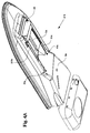
- Figure 1 represents a plan-view of a monocoque body of the bearing type, particularly for ironing-board.
- Figure 2 represents a side view and in part, in longitudinal section according to axis A-A, of the monocoque body as in preceding Figure.
- Figure 3 represents a view taken from the end of the working surface, relatively to the head of the monocoque body.
- Figure 4 represents a plan-view of an slide associable to a supporting stand leg.
- Figure 5 represents a frontal view of the slide as in Figure 4 taken in section along axis A-A.
- Figure 6 represents a view of the slide as in Figures 4 and 5 taken in section along axis B-B.
- Figures 7 and 8 illustrate respectively, an internal-external view of one side of said slides as in preceding Figures.
- figure 9 represents a cross-sectional view of the monocoque body taken along axis B-B of Figure 1.
- Figure 1A represents a side view of an elastic return device of at least one leg, in which are highlighted at least two of the possible positions of an adjustable slide of anchorage of the extremity.
- Figure 2A represents an enlarged view of one particular of Figure 1; relative to the connection means to the pulling cable.
- Figure 3A represents a sectional view and a frontal view of the connection means to the pulling cable.
- Figure 4A represents a perspective view and from below, of a possible variation to the monocoque body for ironing-board; the solution of which excludes the presence of the pulling cable connection.
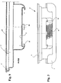
- figures 5A and 6A represent respectively, a schematic plan view and a side view of the monocoque body, and one in longitudinal section.
- a bearing monocoque body (A) particularly for ironing-board, and ironing-board so obtained is made in rigid plastic material, subdivided in two technical zones, respectively a first (b) corresponding to the working surface to be associated, said first zone (b) being made up of a perforated sheet surface with a heating resistance in it, and a second (c) prearranged to support the iron also of the type with boiler.
- the body (A) provides essentially a perimetrical side (1) that protracts perpendicularly in regard to the base (2) for more than a centimetre, delimiting in this way said first technical area (b) and recalls in a certain way, plan-view, the typical elongated shape of a working surface. Therefore a rather deep and wide housing is obtained, with a base (2) having several levels. This is because at a greater depth, obtained in an intermediate area, a compartment (3) corresponds, that in plant view has the shape of a cochlea, said compartment (3) being able to contain the entire engine group for the suction including the relative fan.
- a first circular wall (3') always obtained monolithically, able to contain a first part of the engine group, followed by a couple of rectilinear and parallel walls (3"), which delimit an outlet path of the air sucked, closed at the bottom by a grid placed on tilted plane (4).
- this provides perpendicular supporting feet (5), said feet having their base inserted in it, and which have the function to support at a certain distance, a perforated heat working surface (not shown), that will then be covered by the flannel and respective cloth.
- a perforated heat working surface not shown
- a somewhat deep container (7) preferably rectangular in shape, provided with own sides (7') that delimit the area.
- a niche (9) can additionally be provided, more or less extended, in the case of rectangular shaped type, to accommodate the different commands and eventual electric-taps for the power supply or power net connection.
- Said container (7) is joined monolithically to the adjacent part (b) by means of a joint connecting surface (7") to form a single piece, and to which corresponds, in the underlying part, a kind of vault (8) to accommodate an extremity of the fixed leg, as part of a support stand (not shown).
- the fixing of the latter is obtained by associating to the first shaped base (8) by means of screws, a semicircular countershape, realizing the ring that vices the extremity of said leg, in this case have an "L" shape.
- part (b) of body (A), corresponding to the underlying side of base (2) in particular, is formed in such a way to obtain, always monolithically, a rack, or a fish bone rack (10) obtained centrally in relation to two lateral guides (11) respectively right and left, parallel and coplanar.
- On the side of said slide (12), is a large hole, where the L shaped extremity is introduced and there the end ensured of an opposite movable leg, which is part of the ironing-board compass support stand.
- the bearing monocoque body (A) particularly for ironing-board, and ironing-board so obtained is of the type in rigid plastic material, subdivided in two technical zones, respectively a first zone, corresponding to the working surface to be associated, being made up of a perforated sheet surface in which a resistance is inserted, and eventually a second zone, prearranged for support of the iron and optionally of the type with boiler.
- Said body (A) is sustained by a couple of legs, that have a cross connection (X shape) or compass, comprise a first static leg having its end hinged steadily to said body, while the second leg is movable being able to be, (the corresponding end) moved longitudinally and allowing the engagement (stopping and locking) along the underlying braking rack means in said body (A).
- body (A) is formed in such a way to obtain, always monolithically, a rack (1A) obtained centrally in relation to two lateral guides respectively right and left, parallel and coplanar one to the other.
- Said guides have a "C" shaped section, and can protrude or be enclosed inside of the body.
- Said guides slidingly engage a box slide (2A) which is provided laterally of engaging means, and is able to be constrained along said guides.
- a box slide (2A) which is provided laterally of engaging means, and is able to be constrained along said guides.
- On the side of said slide (2A) at least one seat (3A) is obtained where is introduced and there ensured, the extremity of an "L" shaped opposite movable leg, as part of the support stand.
- the selective locking, in the position desired, of the slide (2A), to which a different height of the surface corresponds, alternatively obtaining the disengagement from the rack (1A), is ensured by means of an elastic return lever (4A).
- a head (6'A) of the cable (6A), by means of the interposition of a stop (8) is associated to the extremity (7'A) of a pulling helical spring (7A), whose opposite extremity (7"A) is anchored steadily inside the structure of the monocoque body (A).
- the other head (6"A) of the cable (6A) is engaged into the slide (2A), supporting an extremity of the movable leg.
- the slide (2A) when the ironing-board is closed, and therefore with the legs close together, the slide (2A) is in a position (b'A) or at the end of the stroke in respect to the rack (1A). In that case being constrained to the spring (7A), the latter will have a distended configuration. Raising the ironing-board (A), the lack of obstacles at the lower extremity of the movable leg, causes its release, in contrary obtaining the elastic return (if not locked) of the slide (2A), effected by the spring (7A). In that case the slide (2A) may be arranged operatively along the rack (1) in a preferential position (b").
- the extremities of said springs (10A, 10'A) engage the ends of a couple of cables (11A, 11'A), which protract longitudinally close to the body and parallel one to the other to anchor from the opposite side directly to the slide (2A). It is possible to see additionally that a part of said pulling cables (11A, 11'A) and springs (10A, 10'A) are enclosed inside the body, preventing even involuntary access.
- the part of body (9A) provides at one side, the realization of a couple of holes (9'A), through which exit the extremities of the cables (11A, 11'A) to be anchored to the corresponding slide (2A), from both sides.
- the respective perforated ironing plate to be fixed in said upper opening (b), by screws in said spacer protrusions (5'), is indicated with (pp).
Landscapes
- Engineering & Computer Science (AREA)
- Textile Engineering (AREA)
- Irons (AREA)
Claims (16)
- Bügelbrett mit einem selbsttragenden Stütz-Gehäusekörper (A), peripher angeordnet mit einer Spannseite (1), die eine obere Öffnung (b) definiert, die sich über die ganze obere beheizte Arbeitsbügelfläche erstreckt, wobei besagte Arbeitsbügelfläche aus einer durchlochten Metall-Bügelplatte (pp) besteht, mit einem Luftansaugmittel darunter, um Luft über besagte Arbeitsbügelfläche zu saugen, gekennzeichnet dadurch, daß besagter selbsttragender Stütz-Gehäusekörper (A) umfaßt:einen Ventilatorsitz in seinem Innern zur vollständigen inneren Umschließung von Saugventilator-Mitteln (3), um Luft durch die Öffnungen besagter beheizter Arbeitsbügelfläche zu saugen (b);ein oberes stützendes vorspringendes Distanzstück (6), am Umfang angeordnet und einstückig mit besagtem selbsttragenden Körper und senkrecht zu diesem angeordnet, um besagte beheizte Arbeitsbügelfläche entlang eines oberen Umfangsrandes (6) an der Innenseite besagter oberen Öffnung zu stützen (b), wobei unterhalb Befestigungsmittel für die Befestigung der betreffenden Kabel vorgesehen sind;nach unten und außen, bei der unteren Oberfläche des besagten selbsttragenden Körpers (A), ist ein Sitz für die Verankerung des statischen Endes eines verschließbaren Umfangs-Standbeins auf einer Seite erhalten (8), während das gegenüberliegende Bein in Eingriff mit einem Beinscharniergleitkörper (2A, 3A) ist, der gleitend auf Führungen (11) verstellbar ist, vollständig erhalten aus dem besagten selbsttragenden Körper (A) und außerdem einstückig mit dem selbsttragenden Körper, längs und in der Mitte besagter Führungen (11) ein gezähntes Gestell (1A), das mit Gestellmitteln zusammenarbeitet, um besagten Beinscharniergleitkörper in Eingriff zu bringen und freizugeben (2A,3A),besagter selbsttragender Stütz-Gehäusekörper (A) ist aus geformtem Kunststoff hergestellt.
- Bügelbrett mit selbsttragendem Stützkörper nach Anspruch 1, gekennzeichnet dadurch, daß besagte Arbeitsbügeloberfläche aus einer durchlochten Blechfläche besteht, in der ein Heizwiderstand befestigt ist.
- Bügelbrett nach den vorherigen Patentansprüchen, gekennzeichnet dadurch, daß besagter selbsttragender Körper, der die Arbeitsoberfläche betrifft, um die besagte erste Öffnung (b) herum im wesentlichen einen erhöhten Umfangsseitenrand (1) vorsieht, der sich senkrecht erstreckt, wobei die innere Form in mehrere Stufen nach unten abgestuft ist, mit einer weniger tiefen, die einen Zwischenboden (2) darstellt, der den besagten Sitz des Luftansaugmittels (3) begrenzt, wobei besagter Sitz eine Schneckenform aufweist.
- Bügelbrett mit selbsttragendem Stützkörper nach Anspruch 3, gekennzeichnet dadurch, daß besagter Sitz für die innere Ansaugung (3) eine erste kreisförmige Wand (3) aufweist, gefolgt von einem Paar von geradlinigen und parallelen Wänden (3"), welche einen Ausgang für die Luft bilden, die durch besagtes Gitter (4) angesaugt wird, das sich auf einer schiefen Ebene befindet.
- Bügelbrett mit selbsttragendem Stützkörper nach den vorherigen Patentansprüchen, gekennzeichnet dadurch, daß die Innenfläche des besagten Zwischenbodens (2) senkrechte Stützfüße (5) aufweist, die mit einem Ende an diesem befestigt sind.
- Bügelbrett mit selbsttragendem Stützkörper nach den vorherigen Patentansprüchen, gekennzeichnet dadurch, daß entlang des Umfangs von besagter erster Öffnungsfläche (b) und im Innern des erhöhten Seitenrands (1) des selbsttragenden Körpers (A) Stege am Rand des betreffenden Bügelarbeitsflächensitzes (6) vorgesehen sind, unterbrochen von senkrechten Räumen (5) zwecks Verschraubung.
- Bügelbrett mit selbsttragendem Stützkörper nach den vorherigen Patentansprüchen, gekennzeichnet dadurch, daß [in] der technischen Fläche (c) neben besagtem selbsttragenden Kunststoffkörper (A) ein tiefer Heizwasserbehälter erhalten wird (7), im wesentlichen rechteckig und mit eigenen Seiten (7), der die Fläche zum Tragen des betreffenden Eisenhandwerkzeugs begrenzt.
- Bügelbrett mit selbsttragendem Stützkörper nach den vorherigen Patentansprüchen, gekennzeichnet dadurch, daß entlang einer Seite des Behälters (7), eine Nische (9) vorgesehen ist.
- Bügelbrett mit selbsttragendem Stützkörper nach den vorherigen Patentansprüchen, gekennzeichnet dadurch, daß besagter Hitzewasserboiler-Behälter (7) einstückig mit dem benachbarten Teil besagter oberer Öffnung (b) des besagten selbsttragenden Stützkörpers (A) verbunden ist, mittels einer Verbindungsfläche (7"), und der in dem darunterliegenden Teil ein Sitz (8) entspricht, zur festen Aufhängung eines Ende eines der besagten Beine, mit Verbindung einer schließenden ringförmigen Gegenform mit der ersten geformten Basis (8).
- Bügelbrett mit selbsttragendem Stützkörper nach den vorherigen Patentansprüchen, gekennzeichnet dadurch, daß besagte seitliche Führungen einen "C"-förmigen Abschnitt aufweisen (11), der gleitend in besagten Gleitkörper (12, 2A,3A) eingreift, ausgestattet mit Längsstegen (12), die entlang besagter Führungen (11) eingeführt sind.
- Bügelbrett mit selbsttragendem Stützkörper nach den vorherigen Patentansprüchen, gekennzeichnet dadurch, daß in den besagten Gleitkörper (12, 2A,3A) das bewegliche Ende eines Stützbeins eingreift, das mit Hebelmitteln zur selektiven Einstellung versehen ist, wobei es mit besagtem gezähnten Gestell (10) interferiert.
- Bügelbrett mit selbsttragendem Stützkörper nach den vorausgehenden Patentansprüchen, gekennzeichnet dadurch, daß zwei Löcher (13), das eine durchgehend, die andere mit Drehfunktion, entlang der Seitenwände des Gleitkörpers (12) eingebracht werden, und in die ein Kniehebel eingeführt wird, der eine Nocke darstellt, deren Bewegung mit dem darunterliegenden Gestell interferiert (10) und sich nach außen einige Zentimeter weit fortsetzt.
- Bügelbrett mit selbsttragendem Stützkörper nach den vorherigen Patentansprüchen, gekennzeichnet dadurch, daß es außen, entsprechend der unteren Oberfläche der Arbeitsfläche (A), einen Sitz für die Verankerung des statischen Endes des schließbaren Umfangs-Standbeins aufweist, wobei das gegenüberliegende Bein in Eingriff mit einem verstellbaren Gleitkörper (12-2A) ist, das auf Führungen (11) gleitet; bestehend im wesentlichen aus mindestens einem Zugkabel (11A, 11'A), das fast parallel zu dem Bügelbrett liegt, in welchem eines der Enden auf einer Seite in Eingriff mit besagtem Gleitkörper (12-2A) ist, mit dem die Enden eines beweglichen Beines verkeilt sind; auf der anderen Seite in Eingriff mit dem Ende einer elastischen entsprechenden Feder (10A, 10'A), die fest an besagtem Körper verankert ist, wobei der ganze Mechanismus im wesentlichen in dem selbsttragenden Körper eingeschlossen ist (A),
- Bügelbrett mit selbsttragendem Stützkörper nach den vorherigen Patentansprüchen, gekennzeichnet dadurch, daß der Spannrahmen (6A-6) des besagten Gleitkörpers (12-2A) mittels einer Riemenscheibe nach rückwärts orientiert ist (5A).
- Bügelbrett mit selbsttragendem Stützkörper nach den vorherigen Patentansprüchen gekennzeichnet dadurch, daß besagte Riemenscheibe (5A) mit einer Führungsrille ausgestattet ist (5'A-6A).
- Bügelbrett mit selbsttragendem Stützkörper nach den vorherigen Patentansprüchen, gekennzeichnet dadurch, daß besagter selbsttragender Körper (A) einen Sitz (9A) aufweist, der ein Paar von überdeckten Schraubenfedern (10A, 10'A) aufnimmt, die auf einer Seite fest an der Struktur verankert sind.
Applications Claiming Priority (4)
| Application Number | Priority Date | Filing Date | Title |
|---|---|---|---|
| ITTV940122 | 1994-10-27 | ||
| ITTV940122A IT1273913B (it) | 1994-10-27 | 1994-10-27 | Monoscocca portante particolarmente per asse da stiro, ed asse da stiro cosi' ottenuta. |
| ITTV950050U | 1995-09-22 | ||
| IT95TV000050 IT239589Y1 (it) | 1995-09-22 | 1995-09-22 | Dispositivo per agevolare l'apertura e viceversa delle gambe di un'asse da stiro, particolarmente del tipo comprendente una monoscocca |
Publications (3)
| Publication Number | Publication Date |
|---|---|
| EP0712955A2 EP0712955A2 (de) | 1996-05-22 |
| EP0712955A3 EP0712955A3 (de) | 1997-11-05 |
| EP0712955B1 true EP0712955B1 (de) | 2000-04-19 |
Family
ID=26332454
Family Applications (1)
| Application Number | Title | Priority Date | Filing Date |
|---|---|---|---|
| EP19950116793 Expired - Lifetime EP0712955B1 (de) | 1994-10-27 | 1995-10-25 | Bügelbrett |
Country Status (2)
| Country | Link |
|---|---|
| EP (1) | EP0712955B1 (de) |
| DE (1) | DE69516363T2 (de) |
Cited By (3)
| Publication number | Priority date | Publication date | Assignee | Title |
|---|---|---|---|---|
| US6807758B2 (en) | 2001-02-23 | 2004-10-26 | Euro Star S.R.L. | Blowing-type and/or suction-type ironing board |
| DE102005013167A1 (de) * | 2005-03-22 | 2006-09-28 | Hailo-Werk Rudolf Loh Gmbh & Co. Kg | Dampfbügeltisch |
| WO2011033269A1 (en) * | 2009-09-18 | 2011-03-24 | Vale Mill (Rochdale) Limited | Ironing board |
Families Citing this family (4)
| Publication number | Priority date | Publication date | Assignee | Title |
|---|---|---|---|---|
| EP1186698A3 (de) * | 2000-09-08 | 2004-01-07 | Hailo-Werk Rudolf Loh GmbH & Co. KG | Bügeltisch |
| JP2008544827A (ja) * | 2005-07-07 | 2008-12-11 | コーニンクレッカ フィリップス エレクトロニクス エヌ ヴィ | 多機能アイロン台を稼働させる方法 |
| DE102005031960A1 (de) * | 2005-07-08 | 2007-01-11 | Hailo-Werk Rudolf Loh Gmbh & Co. Kg | Bügeltisch |
| CN110629489B (zh) * | 2019-10-18 | 2024-11-15 | 莱克电气绿能科技(苏州)有限公司 | 一种熨衣板组件 |
Family Cites Families (5)
| Publication number | Priority date | Publication date | Assignee | Title |
|---|---|---|---|---|
| DE3486244T2 (de) * | 1983-03-28 | 1995-02-02 | Numatic Int Ltd | Vorrichtung zum Bügeln oder Pressen von Wäsche. |
| IT1215442B (it) * | 1987-04-23 | 1990-02-14 | Bielle Di Breda Lorenzo Mauriz | Tavolo da stiro con piano riscaldato particolarmente per usodomestico. |
| ES2069096T3 (es) * | 1989-12-16 | 1995-05-01 | Coach Enterprises Ltd | Tabla de planchar. |
| JPH05317599A (ja) * | 1992-05-18 | 1993-12-03 | Shimada Phys & Chem Ind Co Ltd | アイロン台 |
| JPH05337299A (ja) * | 1992-06-12 | 1993-12-21 | Sanyo Electric Co Ltd | アイロン掛け台、及びそれを用いるアイロン装置 |
-
1995
- 1995-10-25 DE DE1995616363 patent/DE69516363T2/de not_active Expired - Lifetime
- 1995-10-25 EP EP19950116793 patent/EP0712955B1/de not_active Expired - Lifetime
Cited By (3)
| Publication number | Priority date | Publication date | Assignee | Title |
|---|---|---|---|---|
| US6807758B2 (en) | 2001-02-23 | 2004-10-26 | Euro Star S.R.L. | Blowing-type and/or suction-type ironing board |
| DE102005013167A1 (de) * | 2005-03-22 | 2006-09-28 | Hailo-Werk Rudolf Loh Gmbh & Co. Kg | Dampfbügeltisch |
| WO2011033269A1 (en) * | 2009-09-18 | 2011-03-24 | Vale Mill (Rochdale) Limited | Ironing board |
Also Published As
| Publication number | Publication date |
|---|---|
| DE69516363T2 (de) | 2001-01-04 |
| EP0712955A2 (de) | 1996-05-22 |
| EP0712955A3 (de) | 1997-11-05 |
| DE69516363D1 (de) | 2000-05-25 |
Similar Documents
| Publication | Publication Date | Title |
|---|---|---|
| US8266830B2 (en) | Ironing board having a tiltable body | |
| US10648127B2 (en) | Steam ironing and/or smoothing appliance comprising an ironing board that can be immobilized in various tilted positions | |
| US8033038B2 (en) | Ironing station | |
| EP0712955B1 (de) | Bügelbrett | |
| CN205688244U (zh) | 熨烫家电设备 | |
| RU2413807C2 (ru) | Гладильная доска, имеющая выдвигаемое и вдвигаемое основание | |
| US7007314B2 (en) | Combination baby change table and bath support | |
| US7861440B2 (en) | Ironingboard adustable in height | |
| US5706593A (en) | Compact ironing board securable to an edge | |
| US4932086A (en) | Nursing table | |
| JP2009142691A (ja) | ドラム式洗濯機 | |
| US4783916A (en) | Garment pressing and ironing appliance | |
| ITTV950050U1 (it) | Dispositivo per agevolare l'apertura e viceversa delle gambe di un' asse da stiro, particolarmente del tipo comprendente una monoscocca | |
| AU2003254724B2 (en) | Combination Baby Change Table And Bath Support | |
| KR200148789Y1 (ko) | 보조조리대장치 | |
| JPS60185555A (ja) | 手足温浴装置 | |
| JP2007111480A (ja) | ドラム式洗濯機 | |
| JPH02187Y2 (de) | ||
| JPH0240883Y2 (de) | ||
| US2647516A (en) | Bedside tray-table support | |
| KR890005345Y1 (ko) | 쇼파 겸용 침대 | |
| GB2426193A (en) | A shower apparatus | |
| US7299572B2 (en) | Ironing board | |
| JPS64910Y2 (de) | ||
| KR940007670Y1 (ko) | 식기세척기의 상부바구니 높이조절장치 |
Legal Events
| Date | Code | Title | Description |
|---|---|---|---|
| PUAI | Public reference made under article 153(3) epc to a published international application that has entered the european phase |
Free format text: ORIGINAL CODE: 0009012 |
|
| AK | Designated contracting states |
Kind code of ref document: A2 Designated state(s): DE FR |
|
| 17P | Request for examination filed |
Effective date: 19961010 |
|
| PUAL | Search report despatched |
Free format text: ORIGINAL CODE: 0009013 |
|
| K1C1 | Correction of patent application (title page) published |
Effective date: 19960522 |
|
| AK | Designated contracting states |
Kind code of ref document: A3 Designated state(s): DE FR |
|
| GRAG | Despatch of communication of intention to grant |
Free format text: ORIGINAL CODE: EPIDOS AGRA |
|
| GRAG | Despatch of communication of intention to grant |
Free format text: ORIGINAL CODE: EPIDOS AGRA |
|
| GRAH | Despatch of communication of intention to grant a patent |
Free format text: ORIGINAL CODE: EPIDOS IGRA |
|
| 17Q | First examination report despatched |
Effective date: 19990407 |
|
| GRAH | Despatch of communication of intention to grant a patent |
Free format text: ORIGINAL CODE: EPIDOS IGRA |
|
| GRAA | (expected) grant |
Free format text: ORIGINAL CODE: 0009210 |
|
| AK | Designated contracting states |
Kind code of ref document: B1 Designated state(s): DE FR |
|
| REF | Corresponds to: |
Ref document number: 69516363 Country of ref document: DE Date of ref document: 20000525 |
|
| ET | Fr: translation filed | ||
| PLBE | No opposition filed within time limit |
Free format text: ORIGINAL CODE: 0009261 |
|
| STAA | Information on the status of an ep patent application or granted ep patent |
Free format text: STATUS: NO OPPOSITION FILED WITHIN TIME LIMIT |
|
| 26N | No opposition filed | ||
| PGFP | Annual fee paid to national office [announced via postgrant information from national office to epo] |
Ref country code: FR Payment date: 20141027 Year of fee payment: 20 Ref country code: DE Payment date: 20141027 Year of fee payment: 20 |
|
| REG | Reference to a national code |
Ref country code: DE Ref legal event code: R071 Ref document number: 69516363 Country of ref document: DE |