EP0712965B1 - Evier encastrable - Google Patents
Evier encastrable Download PDFInfo
- Publication number
- EP0712965B1 EP0712965B1 EP95114857A EP95114857A EP0712965B1 EP 0712965 B1 EP0712965 B1 EP 0712965B1 EP 95114857 A EP95114857 A EP 95114857A EP 95114857 A EP95114857 A EP 95114857A EP 0712965 B1 EP0712965 B1 EP 0712965B1
- Authority
- EP
- European Patent Office
- Prior art keywords
- work top
- accordance
- built
- sink
- several
- Prior art date
- Legal status (The legal status is an assumption and is not a legal conclusion. Google has not performed a legal analysis and makes no representation as to the accuracy of the status listed.)
- Expired - Lifetime
Links
- XLYOFNOQVPJJNP-UHFFFAOYSA-N water Substances O XLYOFNOQVPJJNP-UHFFFAOYSA-N 0.000 claims description 69
- 239000011324 bead Substances 0.000 claims description 25
- 238000009434 installation Methods 0.000 claims description 23
- 238000006073 displacement reaction Methods 0.000 claims 1
- 230000015572 biosynthetic process Effects 0.000 description 11
- 230000008901 benefit Effects 0.000 description 8
- 210000004197 pelvis Anatomy 0.000 description 7
- 239000007788 liquid Substances 0.000 description 4
- ORQBXQOJMQIAOY-UHFFFAOYSA-N nobelium Chemical compound [No] ORQBXQOJMQIAOY-UHFFFAOYSA-N 0.000 description 3
- 210000003903 pelvic floor Anatomy 0.000 description 3
- 239000000945 filler Substances 0.000 description 2
- 235000021190 leftovers Nutrition 0.000 description 2
- 239000004033 plastic Substances 0.000 description 2
- 239000011347 resin Substances 0.000 description 2
- 229920005989 resin Polymers 0.000 description 2
- 229910001220 stainless steel Inorganic materials 0.000 description 2
- 239000010935 stainless steel Substances 0.000 description 2
- 239000002699 waste material Substances 0.000 description 2
- 239000002023 wood Substances 0.000 description 2
- 240000008415 Lactuca sativa Species 0.000 description 1
- 229910000831 Steel Inorganic materials 0.000 description 1
- 230000006978 adaptation Effects 0.000 description 1
- 238000005266 casting Methods 0.000 description 1
- 238000004140 cleaning Methods 0.000 description 1
- 239000011248 coating agent Substances 0.000 description 1
- 238000000576 coating method Methods 0.000 description 1
- 150000001875 compounds Chemical class 0.000 description 1
- 230000005574 cross-species transmission Effects 0.000 description 1
- 239000003599 detergent Substances 0.000 description 1
- 230000001771 impaired effect Effects 0.000 description 1
- 238000012423 maintenance Methods 0.000 description 1
- 238000004519 manufacturing process Methods 0.000 description 1
- 239000000463 material Substances 0.000 description 1
- 238000005259 measurement Methods 0.000 description 1
- 239000002184 metal Substances 0.000 description 1
- 238000010137 moulding (plastic) Methods 0.000 description 1
- 239000002245 particle Substances 0.000 description 1
- 230000002093 peripheral effect Effects 0.000 description 1
- 239000006223 plastic coating Substances 0.000 description 1
- 239000002985 plastic film Substances 0.000 description 1
- 239000008237 rinsing water Substances 0.000 description 1
- 235000012045 salad Nutrition 0.000 description 1
- 238000007789 sealing Methods 0.000 description 1
- 239000010959 steel Substances 0.000 description 1
- 239000003351 stiffener Substances 0.000 description 1
- 238000003860 storage Methods 0.000 description 1
- 235000013311 vegetables Nutrition 0.000 description 1
- 238000003466 welding Methods 0.000 description 1
Images


Classifications
-
- E—FIXED CONSTRUCTIONS
- E03—WATER SUPPLY; SEWERAGE
- E03C—DOMESTIC PLUMBING INSTALLATIONS FOR FRESH WATER OR WASTE WATER; SINKS
- E03C1/00—Domestic plumbing installations for fresh water or waste water; Sinks
- E03C1/12—Plumbing installations for waste water; Basins or fountains connected thereto; Sinks
- E03C1/18—Sinks, whether or not connected to the waste-pipe
-
- A—HUMAN NECESSITIES
- A47—FURNITURE; DOMESTIC ARTICLES OR APPLIANCES; COFFEE MILLS; SPICE MILLS; SUCTION CLEANERS IN GENERAL
- A47L—DOMESTIC WASHING OR CLEANING; SUCTION CLEANERS IN GENERAL
- A47L19/00—Drying devices for crockery or table-ware, e.g. tea-cloths
- A47L19/02—Draining-boards
-
- E—FIXED CONSTRUCTIONS
- E03—WATER SUPPLY; SEWERAGE
- E03C—DOMESTIC PLUMBING INSTALLATIONS FOR FRESH WATER OR WASTE WATER; SINKS
- E03C1/00—Domestic plumbing installations for fresh water or waste water; Sinks
- E03C1/02—Plumbing installations for fresh water
- E03C1/04—Water-basin installations specially adapted to wash-basins or baths
- E03C1/0404—Constructional or functional features of the spout
-
- E—FIXED CONSTRUCTIONS
- E03—WATER SUPPLY; SEWERAGE
- E03C—DOMESTIC PLUMBING INSTALLATIONS FOR FRESH WATER OR WASTE WATER; SINKS
- E03C1/00—Domestic plumbing installations for fresh water or waste water; Sinks
- E03C1/02—Plumbing installations for fresh water
- E03C1/04—Water-basin installations specially adapted to wash-basins or baths
- E03C2001/0417—Water-basin installations specially adapted to wash-basins or baths having space-saving features, e.g. retractable, demountable
Definitions
- the invention is concerned with a better adaptation of one into one Cutout (opening) of a built-in worktop built-in sink, especially with a cover plate such a plate.
- a built-in sink it can e.g. B. one out Stainless steel sheet made by deep drawing and possibly welding Act product, but also a built-in sink made of enamelled steel sheet or a cast from a casting resin optionally provided with fillers or a product made from a plastic molding compound.
- the worktops or cover plates are usually made of a wood-based material and a plastic coating on top provided plates, but recently it can also be z. B. cast Trade plastic sheets; finally (which is becoming more and more unusual) such a cover plate can also from a stainless steel sheet plate provided with stiffeners on its underside be formed.
- Such wood-based or plastic cover plates usually have a panel thickness in fitted kitchens today (Plate thickness) of 40 mm.
- a working or covering mat with a coating with an in this built-in sink with its edge placed on the worktop results from US-A-4 813 087.
- the built-in sink has a normal one Sink and next to this a drainer in the form of a flat Trough, which is between a front and a rear battery bank of the Built-in sink is arranged; the built-in sink also has an outer, circumferential one Edge zone, which has a raised edge bead with a horizontal top forms so that the zones of the built-in sink lying within this edge bead form a recess recessed downwards, all of which face upwards facing surface areas are lower than the ridge of the edge bead.
- the underside of the built-in sink rim forms an annular surface with which the Built-in sink around a panel cut-out on the The top of the worktop rests.
- US-A-4,813,087 thus shows one Worktop with built-in sink with the features of the generic term of claim 1.
- the built-in sink is a sheet metal manufactured component, the shallow trough forming the draining surface up to a depth in the panel cutout, which is at most about 2/3 corresponds to the plate thickness.
- the invention was based on the object a built-in sink with the features of the preamble of claim 1 improve the risk of being on the sink in the area of their work or Leakage liquids spill over the edge of the sink, is reduced without the under the built-in sink in Area of their work or drainer space in reduce its height so that it is no longer suitable for installing a built-in appliance, like a dishwasher.
- This task will solved by a worktop according to claim 1.
- the basic idea of the invention is therefore to be seen in the fact that compared to conventional built-in sinks of the type mentioned the depth of the formation in Area of the worktop or drainer of the built-in sink is enlarged so that in this area the shape of the plate thickness of the cover plate, in the built-in sink is used more completely than in the known Built-in sinks are the case - the latter protrudes from the drainer forming area of the built-in sink usually only about 25 to a maximum 30 mm deep into the cover plate or its cutout; inventively Therefore, compared to known built-in sinks, the shape is deepened so that in the sink area forming the draining area the built-in sink projects approximately to the level of the underside of the cover plate, d. H.
- this level e.g. 1, 2 or 3 mm
- this level e.g. 1, 2 or 3 mm
- the surface zone of the sink which forms the draining surface, could be in the installed condition run horizontally, but usually has one slight slope towards a basin adjacent to the drainer the built-in sink.
- embodiments of the Built-in sink according to the invention in which the smallest vertical distance Underside of the formation of said ring surface at least approximately 3/4 of the thickness of the worktop is (the smallest vertical distance mentioned should not be more than ⁇ 15%, preferably not more than ⁇ 10% and ideally deviate from the measurement by no more than ⁇ 5%, which is 3/4 of the thickness of the cover plate).
- the inventive design of a built-in sink ensures that all sink areas that are suitable for working in or on the sink surrounded by a relatively high edge bead be, so that the built-in sink according to the invention with a pronounced Schwallrand is covered by the much better than the known built-in sinks it is prevented that liquids accumulating on the sink over the Slosh out the edge of the sink. Further, by deepening the formation achievable advantages will be explained later. All of these benefits but are achieved without that in the built-in sink area under the cover plate available space z. B. one Underbench cabinets impaired in terms of its use is because the space unused in the known built-in sinks below the drainer, but still within the cutout the cover plate, can never be used can.
- the built-in sink according to the invention is particularly advantageous in which the surface zone forming the draining surface the built-in sink is adjacent to its edge zone, d. H. at which the drainer is not about z. B. between two pools , be it two sinks or one sink and a smaller pool (so-called left-over pool).
- built-in sinks There are two common types of built-in sinks: Usually the built-in sink is in the cutout of the cover plate used that with the outermost area of their Edge zone rests on the top of the cover plate, d. H. on the edge area surrounding the cover plate cutout the top of the cover plate; one is less common second type of installation, with the built-in sink in the cut-out in the cover plate is used that the ridge of the bead is flush with the top of the cover plate, d. H. that the ridge of the bead does not rise above the level of the The top of the cover plate protrudes.
- Inset sink leads the sink design according to the invention so if necessary to different (in measured in the vertical direction) Formation from the top of the ridge of the ridge.
- the Water outlet device in particular in the form of a mixer tap, attached, but in some cases also an operating element for the drain valve of a basin.
- Such elements hinder the work on a sink the less, the less these elements protrude.
- it is advantageous if one of the Second surface zone of the built-in sink forming the battery bank is lower than the deepest point of the drainer (under which in this case the top of the bottom of the drainer is to be understood, since usually on the top ribs projecting from this floor are provided).
- Built-in sinks include two side by side Basin, between which one the two basins from each other separating bar-shaped sink area runs. It can are two large sinks, preferably owns a built-in sink according to the invention, however, two different large basins, namely a large sink and a smaller one Basin, which is usually used as a residual basin or trough referred to as.
- the ridge of the bar-shaped sink area lies between the Basin advantageously deeper than the other upper edge areas the basin.
- the comb can do this web-shaped sink area form an overflow, so that Water from a crowded basin across this ridge flow into an adjacent pool and drain from it can without flooding other sink areas become.
- the Built-in sink so that the battery bank second surface zone is higher than the crest of the web-shaped sink area so as to prevent the Battery bank is flooded and liquid through the in the opening provided for the battery bank downwards seeps.
- a built-in sink according to the invention with a larger one and a smaller pool, it is also recommended that Battery bank - as known per se - behind the smaller one Arrange basin and so the behind this smaller basin to use the available space for the battery bank.
- the smaller basin can also be used in the Built-in sink that be placed with a front and a rear battery bank can be equipped one at the rear and the other at the front edge of the built-in sink is arranged adjacent, the smaller Basin is located between the two battery banks.
- a front one and a rear battery bank can also be used without such a smaller pool or without the arrangement described of the two battery banks relative to one realize smaller pools.
- the built-in sink according to the invention which has a water outlet device have from a provided in the battery bank Opening can be pulled out into a position of use is. Then the greater depth of the formation leads Inset sink that when the water spout is lowered is, d. H. is in its non-use position, the built-in sink completely or partially, and cover also in the area of the water outlet device can, especially by means of one or more cover plates, which can easily be designed so that the cover plate in the area covered by the edge bead inserts appropriately, d. H. fits against the inside of the bead is applied.
- the water outlet opening projects the least when it is not in use over the top of the battery bank addition, if it is designed according to the invention that an area provided with a water outlet opening Water outlet device in a non-use position the latter immediately above the level of the top of the battery bank because it is only necessary that some Area of the water outlet device can be detected, around them in their use position from the opening upwards to be able to pull out.
- the water outlet device could e.g. B. the shape of a with the hose passed through said opening have a shower head provided at one end of the hose.
- the Water outlet device approximately perpendicular to the top of the sink extending tubular portion, which slidably held in the opening in its longitudinal direction and from a lower non-use position upwards in the position of use can be raised, because such a tubular
- the area can be easily with holding means such.
- the said tubular area becomes special recommended to use a water outlet device approximately L-shaped tube to provide the approximately tubular area perpendicular to the top of the sink forms, because then the water outlet device not just between their non-use positions and move their position of use back and forth, but them also forms the usual, crane-like water outlet, without in lowered state, d. H. in their non-use position, noticeably protrude over the actual top of the sink.
- the said tubular area has a circular outer cross section and the opening in the battery bank is circular, so the built-in sink can be designed so that the tubular area and thus the entire water outlet device is rotatable in the opening so that the water outlet device can pivot in a known manner to z. B. the water outlet opening either via one or to bring the other pelvis.
- An actuator for a water outlet valve device could be attached to the water outlet device itself be if the arrangement is such that this actuator lowering the water outlet device not hindered or even prevented.
- an actuator for a Water outlet valve device from the actual water outlet device separately and especially on the battery bank is arranged, because then such disabilities can arise anyway do not result, and the actuator can easily be designed so that it is over the top the actual built-in sink does not protrude more than the water outlet device in its non-use position.
- the actuating element is arranged separately this is preferably next to the water outlet device arranged on the battery bank, if necessary but instead on the already mentioned second battery bank, while the water outlet device is on the another battery bank.
- particularly preferred embodiments are distinguished the built-in sink according to the invention by at least a cover plate that can be placed on this.
- Built-in sink is supposed to be a plastic sink act which consist of a filled with filler particles Cast resin and then polymerized the latter has been.
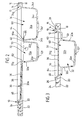
- An edge zone 10 runs around the built-in sink, which forms a raised edge bead 12, the comb 14 as flat, horizontal surface is designed. Outside forms the Edge zone 10 has a support flange 16 on its underside a flat and horizontal ring surface 18 is formed.
- this built-in sink can be used as an opening designed cutout 20 of a cover plate 22 for a built-in cupboard of a fitted kitchen or the like be that with this ring surface 18 on the surface 24 of the cover plate 22 rests.
- the cutout 20 on its upper, peripheral edge with a milled in Level is provided, the outer dimensions of which match the built-in sink, and in which the sink as a whole is placed on the step so that the comb 14 with the surface 24 of the cover plate 22 is flush - as is would then result from the following, then the built-in sink be designed somewhat differently according to the invention.
- the built-in sink according to the invention 1 now forms the lower edge in use front edge 26 of the built-in sink and the upper edge in FIG. 1 the rear edge 28 of the built-in sink.
- the draining surface 30 has a flat, according to FIG. 1 and FIG. 2 slightly sloping floor 36 from left to right, on the radiating ribs 38 are formed.
- Behind the residual pool 32 is a larger, rear battery bank 40, in front of the leftover pool a smaller, front one Battery bank 42.
- the side walls of the residual pool 32 were designated 32a, 32b, 32c and 32d, the bottom of the residual pool with 32e, and accordingly the side walls the sink 34 with 34a, 34b, 34c and 34d, the bottom of the sink with 34e.
- the pelvic floors 32e and 34e each have a drain opening 32f and 34f.
- Form between the two pools 32 and 34 whose side walls 32d and 34b a web 44, the comb with 44a was designated.
- the remaining areas of the top edges of the both pools were designated 32g and 34g, respectively.
- the inner flank of the edge bead 12 forms an inclined surface 46, which, as can best be seen in FIG. 2, along the edge bead 12 is of different widths or depths and runs obliquely from top to bottom from outside to inside.
- Openings can already be made in the two battery banks 40 and 42 50, 52 and 54 be formed, which of the assembly a water outlet device, an operating element for the latter and / or an operating element or operating elements for a drain valve or drain valves serve both pools 32 and 34, but these openings can all or part of it only when the built-in sink is installed getting produced.
- the built-in sink accordingly with a shape designated as a whole by 60 provided, to which the circumferential inclined surface 46 as well belongs to the drainer 30, the two basins 32 and 34 and the two battery banks 40 and 42.
- This shape 60 is now graded so that the surfaces of the two battery banks 40 and 42, both of which are on the same level, are lower than the lowest point on the top of the Bottom 36 of the drainer 30, so that between this and the two battery banks each have a stage 62 or 64 results.
- the comb 44a of the web 44 lies between the two pools even deeper than the tops of the two battery banks, so that between these and the Web ridge 44a each gives a further step 66 or 68. Due to the radial course of the ribs 38 the Advantage achieved that accumulating on the drainer 30 Drip water or splash water "centered" and at least is almost completely derived into the residual pool 32.
- the first embodiment shown in Figures 1 to 3 the built-in sink according to the invention is for installation in a cover plate is provided, as shown in Fig. 2 has been; with this type of installation, as already mentioned, the formed by the bead 12 or its support flange 16 Ring surface 18 on the top 24 of the cover plate 22.
- the latter usually has a plate thickness (thickness) of 40 mm, which according to the invention leads to the following design of the formation 60 of the built-in sink leads:
- the underside of the draining surface 30, designated 30a has at its lowest point - measured in the vertical direction - A distance "A" from the ring surface 18 and on it highest point a distance "B" from the ring surface 18.
- the formation 60 designed so that the distance A approximately is equal to the plate thickness of the cover plate 22, in Usually this is about 40 mm. Because of the slope the bottom 36 of the drainer 30, however, is the distance B smaller than the plate thickness of the cover plate 22, and in particular the distance B is approximately 3/4 of this plate thickness.
- the highest area of the built-in sink with the Top 24 of the cover plate 2 flush when installed should be the distance A '(again in vertical Direction measured) the deepest point of the bottom 30a of the Drainer 30 from the top of the ridge 14 of the bead 12 approximately 40 mm (with a plate thickness of the cover plate 22 by 40 mm), while - depending on the slope of the drainer 30 - the distance B 'of the highest point of the Bottom 30a from the top of the comb 14 z. B. approximately is 3/4 of the thickness of the cover plate 22.
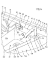
- the actual built-in sink differs from that according to Figures 1 to 3 only in that the tops of the two battery banks 40 'and 42', the crest of the web 44 ' between the two pools and all areas of the top edges 32g 'and 34g' of the two pools are on the same level, however, deeper than the deepest point of the bottom 36 'of the drainer 30 '.
- Ribs 38 'of drainer 30' parallel to each other and to the front or rear edge of the built-in sink, although also in this embodiment, a radial course of this Ribs would bring benefits.
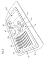
- Actuator 102 which is an actuator for a not shown and below the built-in sink valve device for the water outlet device 100 should act.
- the actuator 102 can, for example, with a lever 104 that can be swiveled up be provided, with the help of which the actuating element 102 can also rotate about a central, vertical axis by swinging lever 104 up water from the water outlet device 100 leak and its temperature through To be able to adjust the rotation of the actuating element 102.
- the Water outlet device 100 has an inverted L-shape Pipe 106, in its upper and front end according to FIG.
- a straight tube section 112 of the Pipe 106 is vertical, i. H. perpendicular to the top the rear battery bank 40 and is in the vertical direction slidably guided in the sink opening 52; also can straight tube section 112 around its central, vertical Longitudinal axis are rotated, d. H. it is in the sink opening 52 also rotatably held so that the water outlet opening 108 both over the remnant pool 32, as well as over the sink 34 can be pivoted.
- 4 shows the water outlet device in its raised position, like results from the above, but it can also be divided into one Can be pushed down when not in use the short, horizontal area of the tube 106 immediately located above the top of the rear battery bank 40 or even against this top.
- FIGS 5A and 5B are for vertical displaceability and the pivotability of the water outlet device 100 essential parts of the latter are shown.
- the water spout is included 100 a straight outer tube 120 with a upper, against the top of the battery bank 40 Ring collar 122, on which there is an external thread 124 of the outer tube 120 connects.
- a straight inner tube 130 is in the outer tube 120 slidable in the vertical direction and about its central longitudinal axis rotatably guided; has the inner tube at its upper end 130 an external thread on which the tube 106 with an internal thread is screwed on.
- the outside diameter of tube 106 is equal to the outer diameter of the inner tube 130, so that the unit formed from the tubes 106 and 130 in the outer tube 120 can be moved vertically and in Ring collar 122 can arrange an annular seal 140 which is sealing against the outer circumference of this unit 106, 130.
- a unit (not shown) runs in this unit flexible hose that connects water to the shower head 110 forms.
- a Lock the water outlet device 100 or the unit 106, 130 ensure in their upper position of use, but at the same time the pivoting of the water outlet device 100 around the central longitudinal axis of the pipe area 112 or the inner tube 130 allow.
- These funds can z. B. a grub screw screwed into the inner tube 130 150 and a corresponding, slot-shaped backdrop guide in Include outer tube 120 for the grub screw 150.
- the lowerability of the water outlet device 100 enables it is not only the built-in sink according to the invention directly in front of a kitchen window or the like, without opening this window by the water outlet device 100 is disabled (if this is in their lowered non-use position), but there is also the advantage that when the water outlet device 100 lowered into its non-use position is, the built-in sink with a possibly multi-part Cover plate completely or partially, and indeed in the area of the water outlet device can.
- Fig. 6 shows that what for ergonomic reasons
- the actuating element 102 can also be advantageous the front battery bank 42 'can be arranged.
- in the 6 shows the water outlet device 100 back in their raised, d. H. in their position of use.
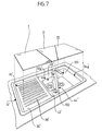
- 7 now shows the built-in sink according to the invention in combination with a first embodiment of a multi-part Cover plate.
- This consists of three cover plate parts I, II and III, which together take up the entire built-in sink can cover, thanks to the also in the field of Drainer 30 or 30 'lower than in the prior art designed formation 60 such that the top of the cover plate or the cover plate parts with the comb 14 of the Edge bead 12 is flush, at least not over this Comb survives.
- the cover plate part I is adapted to the shape of the draining surface 30 or 30 ', the cover plate part II to the shape of one Area of the built-in sink by the two battery banks and the residual pool 32 is formed, and the cover plate part IIIan the area of the built-in sink formed by the sink 34.
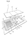
- FIG. 8 shows the built-in sink according to the invention in combination with a second embodiment of the multi-part cover plate.
- all cover plate parts I ', II' and III 'of the same size, and the design of the Built-in sink is such that the one placed on the latter Cover plate part III 'straight up to the water outlet device 100 stretches.
- This embodiment is of course cheaper to manufacture and easier to use since all three Cover plate parts are identical.
Landscapes
- Engineering & Computer Science (AREA)
- Health & Medical Sciences (AREA)
- Life Sciences & Earth Sciences (AREA)
- Hydrology & Water Resources (AREA)
- Public Health (AREA)
- Water Supply & Treatment (AREA)
- Environmental & Geological Engineering (AREA)
- Sink And Installation For Waste Water (AREA)
Claims (34)
- Plan de travail (22) comportant un évier avec épaisseur de paroi régulière encastré dans une découpe (20) du plan, évier qui comprend au moins un bac (32, 34), au moins une première zone de surface formant une surface de travail et d'égouttage (30) et au moins une deuxième zone de surface formant un banc à robinetterie (40, 42), ainsi qu'une zone marginale (10) entourant l'évier encastrable, laquelle forme un bourrelet de bordure surélevé (12) et une surface annulaire plane (18) entourant également l'évier encastrable et située au même niveau que la face supérieure (24) du plan de travail (22), les zones de l'évier encastrable situées à l'intérieur du bourrelet de bordure formant une conformation (60) renfoncée vers le bas dont toutes les zones de surface dirigées vers le haut se trouvent plus bas que la crête (14) du bourrelet de bordure (12), caractérisé en ce que pour agrandir le renfoncement de la face supérieure de la surface d'égouttage (30) par rapport à la crête (14) du bourrelet de bordure (12), la profondeur de la conformation (60) dans la zone de la surface d'égouttage (30) est dimensionnée de telle sorte que la distance verticale maximale (A) entre la face inférieure (30a) de la conformation (60) et la surface annulaire (18) est de 90 % à 110 % de l'épaisseur du plan de travail (22).
- Plan de travail selon la revendication 1, caractérisé en ce que la distance verticale maximale (A ; A') entre la face inférieure (30a) de la conformation (60) et la surface annulaire (18 ; 14) est égale à l'épaisseur du plan de travail (22).
- Plan de travail selon l'une ou l'autre des revendications 1 et 2, caractérisé en ce que la surface d'égouttage (30 ; 30') est adjacente à la zone marginale (10).
- Plan de travail selon l'une ou plusieurs des revendications 1 à 3, caractérisé en ce qu'en vue frontale de l'évier encastrable, le bac (32) se trouve à côté de la surface d'égouttage (30).
- Plan de travail selon l'une ou plusieurs des revendications 1 à 4, caractérisé en ce que la surface annulaire (18) se trouve sur la face inférieure de la zone marginale (10) et cette dernière est réalisée pour venir se poser sur le plan de travail (22) avec cette surface annulaire.
- Plan de travail selon l'une ou plusieurs des revendications 1 à 5, caractérisé en ce que la distance verticale minimale (B; B') entre la face inférieure (30a) de la conformation (60) et la surface annulaire (18 ; 14) est d'au moins ¾ de l'épaisseur du plan de travail (22).
- Plan de travail selon l'une ou plusieurs des revendications 1 à 6, caractérisé en ce que l'arête supérieure (32g, 34g) du bac (32, 34) s'étend vers le haut tout au plus jusqu'au niveau de l'emplacement le plus profond de la surface d'égouttage (30 ; 30').
- Plan de travail selon l'une ou plusieurs des revendications 1 à 7, caractérisé en ce que la deuxième zone de surface formant le banc à robinetterie (40, 42) se trouve plus bas que l'emplacement le plus profond de la surface d'égouttage (30 ; 30').
- Plan de travail selon la revendication 8, caractérisé en ce que la deuxième zone de surface formant le banc à robinetterie (40, 42) se trouve plus haut qu'un trop-plein (44a, 70) pour le bac (32, 34).
- Plan de travail selon l'une ou plusieurs des revendications 1 à 9, caractérisé par deux bacs (32, 34) situés l'un à côté de l'autre, entre lesquels s'étend une zone d'évier en forme de barrette (44) qui sépare les deux bacs.
- Plan de travail selon la revendication 10, caractérisé en ce que la crête (44a) de la zone d'évier en forme de barrette (44) se trouve plus bas que les autres zones d'arête supérieure (32g, 34g) des deux bacs (32, 34).
- Plan de travail selon l'une des revendications 8 à 11, caractérisé en ce que la deuxième zone de surface formant le banc à robinetterie (40, 42) se trouve plus haut que la crête (44a) de la zone d'évier en forme de barrette (44).
- Plan de travail selon l'une ou plusieurs des revendications 10 à 12, caractérisé en ce qu'un seul (32) des deux bacs (32, 34) est pourvu d'un trop-plein (70) sous la forme d'un orifice de trop-plein ménagé dans l'une (32a) de ses parois latérales (32a, 32b, 32c, 32d).
- Plan de travail selon la revendication 13, caractérisé en ce que les deux bacs (32, 34) présentent des tailles différentes, le petit bac (32) des deux bacs présentant une distance plus grande de la bordure arrière (28) de l'évier encastrable que le grand bac (34), et en ce que l'orifice de trop-plein (70) est ménagé dans la paroi latérale arrière (32a) du petit bac (32).
- Plan de travail selon la revendication 14, caractérisé en ce que le banc à robinetterie (40) est agencé derrière le petit bac (32).
- Plan de travail selon l'une ou plusieurs des revendications 1 à 15, caractérisé par un banc à robinetterie avant (40) et par un banc à robinetterie arrière (42), dont l'un est agencé au voisinage de la bordure arrière (28) de l'évier encastrable et dont l'autre est agencé au voisinage de la bordure avant (26).
- Plan de travail selon les revendications 10, 14 et 16, caractérisé en ce que le petit bac (32) est agencé entre les deux bancs à robinetterie (40, 42).
- Plan de travail selon l'une ou plusieurs des revendications 14 à 17, caractérisé en ce que le petit bac (32) est agencé entre le grand bac (34) et la surface d'égouttage (30 ; 30').
- Plan de travail selon l'une ou plusieurs des revendications précédentes, caractérisé par un dispositif d'écoulement d'eau (100) qui est extractible depuis un orifice (52) ménagé dans le banc à robinetterie (40) jusque dans une position d'utilisation.
- Plan de travail selon la revendication 19, caractérisé en ce qu'une zone (106 ou 110), pourvue d'un orifice d'écoulement d'eau (108), du dispositif d'écoulement d'eau (100) se trouve, en position de non-utilisation de ce dernier, immédiatement au-dessus du niveau de la face supérieure du banc à robinetterie.
- Plan de travail selon l'une ou l'autre des revendications 19 et 20, caractérisé en ce que le dispositif d'écoulement d'eau (100) comprend une zone tubulaire (112) qui s'étend approximativement perpendiculairement à la face supérieure de l'évier et qui est retenue mobile en direction longitudinale dans l'orifice (52) et qui est susceptible d'être soulevée hors d'une position de non-utilisation vers le haut jusque dans la position d'utilisation.
- Plan de travail selon la revendication 21, caractérisé en ce que le dispositif d'écoulement d'eau (100) comprend un tube (106) approximativement en forme de L qui forme la zone tubulaire (112) qui s'étend approximativement perpendiculairement à la face supérieure de l'évier.
- Plan de travail selon l'une ou l'autre des revendications 21 et 22, caractérisé en ce que la zone tubulaire (112) possède une section extérieure circulaire, l'orifice (52) étant circulaire et la zone tubulaire pouvant tourner dans l'orifice.
- Plan de travail selon l'une ou plusieurs des revendications 19 à 23, caractérisé en ce qu'un élément d'actionnement (102) pour un dispositif à clapet d'écoulement d'eau est séparé du dispositif d'écoulement d'eau (100) et agencé sur le banc à robinetterie (40 ou 42).
- Plan de travail selon la revendication 24, caractérisé en ce que l'élément d'actionnement (102) est agencé à côté du dispositif d'écoulement d'eau (100) sur le banc à robinetterie (40).
- Plan de travail selon les revendications 16 et 24, caractérisé en ce que le dispositif d'écoulement d'eau (100) est agencé dans la zone du banc à robinetterie arrière (40') et l'élément d'actionnement (102) est agencé dans la zone du banc à robinetterie avant (42').
- Plan de travail selon l'une ou plusieurs des revendications 19 à 26, caractérisé par au moins une plaque de recouvrement (I, II, III) susceptible d'être posée sur l'évier encastrable.
- Plan de travail selon la revendication 27, caractérisé en ce que la plaque de recouvrement (I, II, III) est réalisée et susceptible d'être posée sur l'évier encastrable de manière à s'appuyer de façon ajustée contre la face intérieure (46) du bourrelet de bordure (12).
- Plan de travail selon l'une ou l'autre des revendications 27 et 28, caractérisé par plusieurs plaques de recouvrement (I, II, III) dont l'une, la première (I), est adaptée à la configuration de la surface d'égouttage (30 ; 30').
- Plan de travail selon la revendication 29 et selon l'une ou plusieurs des revendications 10 à 18, caractérisé par une deuxième plaque de recouvrement (II ou III) qui est adaptée à la configuration de l'un des bacs (32 ou 34), ainsi que par une troisième plaque de recouvrement (III ou II) par laquelle, conjointement avec la première et la deuxième plaque de recouvrement, la totalité de l'évier encastrable peut être recouverte.
- Plan de travail selon l'une ou l'autre des revendications 27 et 28, caractérisé en ce qu'il est prévu plusieurs et en particulier trois plaques de recouvrement réalisées identiques (I', II', III'), au moyen desquelles, en position posée les unes à côté des autres, la totalité de l'évier encastrable à l'intérieur du bourrelet de bordure (12') peut être recouverte.
- Plan de travail selon l'une ou plusieurs des revendications 27 à 31, caractérisé en ce que le dispositif d'écoulement d'eau (100) est configuré de telle sorte, et la distance verticale entre le banc à robinetterie (40 ; 40') et le niveau de la crête (14) du bourrelet de bordure (12) est dimensionnée de telle sorte que, lorsque le dispositif d'écoulement d'eau est dans sa position de non-utilisation et que la plaque de recouvrement (I, II, III) est posée, sa face supérieure se trouve tout au plus au niveau de la crête (14) du bourrelet de bordure (12).
- Plan de travail selon l'une ou plusieurs des revendications 14 à 32, caractérisé en ce que le petit bac (32) est agencé au voisinage de la surface d'égouttage (30) et cette dernière est pourvue de nervures (38) qui convergent en forme de rayons en direction du petit bac.
- Plan de travail selon l'une ou plusieurs des revendications précédentes, caractérisé en ce que le plan de travail (22) présente une épaisseur d'environ 40 mm et la distance verticale maximale (A ; A') entre la face inférieure (30a) de la conformation (60) et la surface annulaire (18 ; 14) est approximativement égale à 40 mm.
Applications Claiming Priority (2)
| Application Number | Priority Date | Filing Date | Title |
|---|---|---|---|
| DE4440905 | 1994-11-17 | ||
| DE4440905 | 1994-11-17 |
Publications (2)
| Publication Number | Publication Date |
|---|---|
| EP0712965A1 EP0712965A1 (fr) | 1996-05-22 |
| EP0712965B1 true EP0712965B1 (fr) | 2003-04-02 |
Family
ID=6533454
Family Applications (1)
| Application Number | Title | Priority Date | Filing Date |
|---|---|---|---|
| EP95114857A Expired - Lifetime EP0712965B1 (fr) | 1994-11-17 | 1995-09-21 | Evier encastrable |
Country Status (2)
| Country | Link |
|---|---|
| EP (1) | EP0712965B1 (fr) |
| DE (2) | DE4444657A1 (fr) |
Families Citing this family (9)
| Publication number | Priority date | Publication date | Assignee | Title |
|---|---|---|---|---|
| DE19618376C1 (de) * | 1996-05-08 | 1998-01-22 | Blanco Gmbh & Co Kg | Einbauspüle |
| DE10134311A1 (de) * | 2001-07-14 | 2003-02-27 | Blanco Gmbh & Co Kg | Verfahren zum Zuordnen von Zubehörteilen zu Spülen |
| DE10237845A1 (de) * | 2002-08-19 | 2004-03-04 | Cramer Sr, S.R.O. | Küchenabdeckung |
| US20060242761A1 (en) * | 2005-02-11 | 2006-11-02 | Tod Babick | Dual capacity sink |
| CN102605837B (zh) * | 2005-02-11 | 2015-09-30 | 科勒公司 | 双容量水池 |
| CN105904129B (zh) * | 2016-06-27 | 2017-07-07 | 宁波塞尔翔鹰金属制品有限公司 | 一种水槽翅焊接结构及焊接方法 |
| DE202017105096U1 (de) * | 2017-08-24 | 2018-08-30 | Reich Gmbh Regel- Und Sicherheitstechnik | Wasserarmatur, insbesondere für einen Wohnwagen, Caravan, Motorcaravan oder ein Boot, Anordnung einer solchen Wasserarmatur an einem Einrichtungsgegenstand, sowie Anhänger und Fahrzeug |
| DE102019218650A1 (de) * | 2019-11-29 | 2021-06-02 | BSH Hausgeräte GmbH | Spülbecken mit verfahrbarer Einsatzplatte und aktiver Abführvorrichtung für Restmedien auf der Einsatzplatte |
| DE102021123455A1 (de) | 2021-09-10 | 2023-03-16 | Grohe Ag | Spülbecken und Spülbeckenanordnung mit einem solchen Spülbecken |
Citations (1)
| Publication number | Priority date | Publication date | Assignee | Title |
|---|---|---|---|---|
| US4813087A (en) * | 1986-11-20 | 1989-03-21 | Niro-Plan Ag | Kitchen sink unit with refuse disposal opening |
Family Cites Families (13)
| Publication number | Priority date | Publication date | Assignee | Title |
|---|---|---|---|---|
| FR990965A (fr) * | 1949-07-19 | 1951-09-28 | Perfectionnements aux robinets pour lavabos | |
| GB843863A (en) * | 1957-12-27 | 1960-08-10 | Freedman Brothers Ltd | Improvements relating to receptacles such as washbasins, sinks and baths |
| US3680780A (en) * | 1971-02-23 | 1972-08-01 | Crosweller & Co Ltd W | Ablutionary appliances |
| DE2559619A1 (de) * | 1975-01-07 | 1977-06-30 | Franke Gmbh | Spuele |
| DE3231214A1 (de) * | 1982-08-21 | 1984-02-23 | Friedrich Grohe Armaturenfabrik Gmbh & Co, 5870 Hemer | Sanitaerarmatur |
| DE3437033A1 (de) * | 1984-03-20 | 1985-09-26 | Blanc Gmbh & Co, 7519 Oberderdingen | Spuele |
| DE3421821A1 (de) * | 1984-06-13 | 1985-12-19 | Villeroy & Boch Keramische Werke Kg, 6642 Mettlach | Kuechenspuele |
| DK167450B1 (da) * | 1986-05-14 | 1993-11-01 | Gevipi Ag | Vandhane med udloebstud, der kan indstilles paa mangfoldige maader |
| DE3621151A1 (de) * | 1986-06-24 | 1988-01-07 | Lamprecht Alape | Spuelbecken aus edelstahl, emailliertem stahl, keramik oder kunststoff |
| DE3624090C1 (en) * | 1986-07-17 | 1987-07-09 | Heinz Kiparski | Household sink |
| GB2221388B (en) * | 1988-08-05 | 1992-09-02 | Astracast Plc | Sink unit |
| FR2672369B1 (fr) * | 1991-01-16 | 1995-01-27 | Masco Corp | Douchette de sanitaire amovible et procede d'assemblage. |
| CH686791A5 (fr) * | 1991-11-28 | 1996-06-28 | Kugler Fonderie Robinetterie | Appareil sanitaire. |
-
1994
- 1994-12-15 DE DE4444657A patent/DE4444657A1/de not_active Withdrawn
-
1995
- 1995-09-21 EP EP95114857A patent/EP0712965B1/fr not_active Expired - Lifetime
- 1995-09-21 DE DE59510615T patent/DE59510615D1/de not_active Expired - Fee Related
Patent Citations (1)
| Publication number | Priority date | Publication date | Assignee | Title |
|---|---|---|---|---|
| US4813087A (en) * | 1986-11-20 | 1989-03-21 | Niro-Plan Ag | Kitchen sink unit with refuse disposal opening |
Also Published As
| Publication number | Publication date |
|---|---|
| DE4444657A1 (de) | 1996-05-30 |
| EP0712965A1 (fr) | 1996-05-22 |
| DE59510615D1 (de) | 2003-05-08 |
Similar Documents
| Publication | Publication Date | Title |
|---|---|---|
| DE102011051430B4 (de) | Abwasserablauf mit Geruchsverschluss | |
| EP0299540B1 (fr) | Evier encastrable | |
| EP0712965B1 (fr) | Evier encastrable | |
| DE202009009704U1 (de) | Spülbecken vom Einbautyp | |
| DE20008180U1 (de) | Duschwanne | |
| DE3437033A1 (de) | Spuele | |
| DE19618376C1 (de) | Einbauspüle | |
| DE9314916U1 (de) | Küchenspüle | |
| EP1611827B1 (fr) | Dispositif combiné pour le bain et la douche | |
| DE202015107000U1 (de) | Ablaufsystem | |
| DE3421821A1 (de) | Kuechenspuele | |
| DE102013102379A1 (de) | Ablaufanordnung | |
| AT411421B (de) | Höhenverstellbare duschwanne | |
| DE19908255B4 (de) | Toilette mit heb- und senkbarem Toilettenkörper | |
| DE4121850A1 (de) | Verfahren und vorrichtung zum einsparen von wasser | |
| EP4071312B1 (fr) | Dispositif pour un dispositif d'évacuation disposé dans le sol d'une pièce, ainsi que dispositif d'évacuation doté d'un tel dispositif | |
| EP1975325A2 (fr) | Evier | |
| DE10204683A1 (de) | Becken | |
| EP1221510B1 (fr) | Armature de décharge et de trop-plein avec alimentation d'eau | |
| DE60207871T2 (de) | Spülkasten | |
| AT507463B1 (de) | Ablaufeinrichtung | |
| EP3680402B1 (fr) | Caissons encastrables | |
| DE202025101374U1 (de) | Einrichtung zur Versorgung eines Grauwasserbehälters mit Frischwasser aus einem Frischwasseranschluss und System zur Grauwasserverwendung | |
| EP4481124A1 (fr) | Cuvette sanitaire, en particulier évier | |
| DE1300219B (de) | Spueltischabdeckung |
Legal Events
| Date | Code | Title | Description |
|---|---|---|---|
| PUAI | Public reference made under article 153(3) epc to a published international application that has entered the european phase |
Free format text: ORIGINAL CODE: 0009012 |
|
| AK | Designated contracting states |
Kind code of ref document: A1 Designated state(s): DE FR GB IT NL |
|
| 17P | Request for examination filed |
Effective date: 19961105 |
|
| 17Q | First examination report despatched |
Effective date: 20000901 |
|
| GRAH | Despatch of communication of intention to grant a patent |
Free format text: ORIGINAL CODE: EPIDOS IGRA |
|
| RAP1 | Party data changed (applicant data changed or rights of an application transferred) |
Owner name: BLANCO GMBH + CO KG |
|
| GRAH | Despatch of communication of intention to grant a patent |
Free format text: ORIGINAL CODE: EPIDOS IGRA |
|
| GRAA | (expected) grant |
Free format text: ORIGINAL CODE: 0009210 |
|
| AK | Designated contracting states |
Designated state(s): DE FR GB IT NL |
|
| PG25 | Lapsed in a contracting state [announced via postgrant information from national office to epo] |
Ref country code: NL Free format text: LAPSE BECAUSE OF FAILURE TO SUBMIT A TRANSLATION OF THE DESCRIPTION OR TO PAY THE FEE WITHIN THE PRESCRIBED TIME-LIMIT Effective date: 20030402 |
|
| REG | Reference to a national code |
Ref country code: GB Ref legal event code: FG4D Free format text: NOT ENGLISH |
|
| REF | Corresponds to: |
Ref document number: 59510615 Country of ref document: DE Date of ref document: 20030508 Kind code of ref document: P |
|
| GBT | Gb: translation of ep patent filed (gb section 77(6)(a)/1977) | ||
| NLV1 | Nl: lapsed or annulled due to failure to fulfill the requirements of art. 29p and 29m of the patents act | ||
| ET | Fr: translation filed | ||
| PLBE | No opposition filed within time limit |
Free format text: ORIGINAL CODE: 0009261 |
|
| STAA | Information on the status of an ep patent application or granted ep patent |
Free format text: STATUS: NO OPPOSITION FILED WITHIN TIME LIMIT |
|
| 26N | No opposition filed |
Effective date: 20040105 |
|
| PGFP | Annual fee paid to national office [announced via postgrant information from national office to epo] |
Ref country code: IT Payment date: 20080911 Year of fee payment: 14 Ref country code: FR Payment date: 20080624 Year of fee payment: 14 |
|
| PGFP | Annual fee paid to national office [announced via postgrant information from national office to epo] |
Ref country code: GB Payment date: 20080701 Year of fee payment: 14 |
|
| PGFP | Annual fee paid to national office [announced via postgrant information from national office to epo] |
Ref country code: DE Payment date: 20081030 Year of fee payment: 14 |
|
| GBPC | Gb: european patent ceased through non-payment of renewal fee |
Effective date: 20090921 |
|
| REG | Reference to a national code |
Ref country code: FR Ref legal event code: ST Effective date: 20100531 |
|
| PG25 | Lapsed in a contracting state [announced via postgrant information from national office to epo] |
Ref country code: FR Free format text: LAPSE BECAUSE OF NON-PAYMENT OF DUE FEES Effective date: 20090930 Ref country code: DE Free format text: LAPSE BECAUSE OF NON-PAYMENT OF DUE FEES Effective date: 20100401 |
|
| PG25 | Lapsed in a contracting state [announced via postgrant information from national office to epo] |
Ref country code: GB Free format text: LAPSE BECAUSE OF NON-PAYMENT OF DUE FEES Effective date: 20090921 |
|
| PG25 | Lapsed in a contracting state [announced via postgrant information from national office to epo] |
Ref country code: IT Free format text: LAPSE BECAUSE OF NON-PAYMENT OF DUE FEES Effective date: 20090921 |